Nonreciprocal transmission of neutrons through the noncoplanar magnetic system
Abstract
We report on observation of the time reversal symmetry breaking in an unpolarized neutrons scattering experiment based on a nonreciprocal cell consisting of two magnetic mirrors placed in an external magnetic field. The neutron transmittivity through the system is measured. The time reversal symmetry holds for coplanar magnetic configuration, meaning that the transmission does not vary when the neutron source and detector are interchanged. In the case of a noncoplanar magnetic structure, though, the time reversal symmetry breaks down. Understanding the origin of the nonreciprocity of scattering for spin 1/2 particles opens up new possibilities in the field of nonreciprocal spintronic device development.
pacs:
76.60.Lz 25.40.Dn 61.05.fj 85.75.-dI Introduction
Behavior of a spin 1/2 particle in an inhomogeneous magnetic or exchange field is one of the most fundamental problems in condensed matter physics. The Schrödinger equation for an electron interacting with the exchange field of ferromagnet provides the basis for spintronics which is an actively growing area of fundamental and applied research currently Pulizzi (2012). Numerous physical phenomena in magnetic systems are described using this equation: giant magneto-resistance Baibich et al. (1988); Binasch et al. (1989), topological Hall effect Aharonov and Stern (1992); Li et al. (2013), current induced torques Berger (1996); Slonczewski (1996); Zhang and Li (2004) and etc. A similar equation describes neutron behavior in magnetic medium Izyumov et al. (1991) which is the subject topic of magnetic neutronography. Polarization Izyumov et al. (1991) and Zeeman splitting of a neutron beam in noncollinear field Ignatovich (1978); Felcher et al. (1995); Korneev et al. (1996), neutron spin echo Mezei (1972) and etc. can be understood using Schrödinger equation with Pauli term
| (1) |
where is the momentum operator, is the scalar potential, is the magnetic field, and are the mass and the magnetic moment of neutron, is the unit matrix, is the vector of Pauli matrices and is the spinor wave function. The equation does not include interaction of magnetic field with the particle charge. This is valid for neutrons since they are neutral particles. Sometimes it is a reasonable approximation for electrons in ferromagnets where the exchange field is rather strong and one can neglect the Lorentz force. For electrons, one should substitute the exchange constant for magnetic moment and unit vector along the local magnetization for magnetic induction.
Let us denote as a differential cross-section (DCS), i.e. scattering in an element of the solid angle. In terms of scattering of unpolarized particles the time reversal symmetry can be expressed as the reciprocity theorem Landau and Lifshitz (1977); Deák and Fülöp (2012)
| (2) |
where are the momenta of the incident and scattered neutrons and is the magnetic induction distribution. We refer to the scattering in a certain system is called reciprocal if the DCS is the same for direct and ”time-reversed” processes (below we use the term ”time-reversed” without quotes)
| (3) |
Time reversal symmetry breaking and nonreciprocal scattering occur when the direct and time-reversed scattering processes are not the same
| (4) |
One of the best-known examples of nonreciprocal processes is the light transmission through the Faraday cell. The necessary condition for nonreciprocal light scattering is the absence of spatial and time reversal symmetries (presence of magnetic field or magnetization) Shelankov and Pikus (1992). The microscopic mechanism for nonreciprocal light scattering are the Lorentz force and spin-orbit interaction. Neither of these effects is the case for neutrons, hence, they do not appear in Eq. (1). It means that the requirements for observation of nonreciprocal phenomena for neutrons and other particles described by Eq. (1) are more stringent. Below we discuss an additional symmetry of the DCS as a specific property of the Schrödinger equation with Pauli term Eq. (1). Scattering of light does not have such additional symmetry. In the paper we show that it is possible to create nonreciprocal cell for neutrons.
Understanding the origin of nonreciprocal scattering for spin 1/2 particles opens new possibilities for development of nonreciprocal spintronic devices. Recently a magnetic diode using the nonreciprocal behavior of electrons was proposed Udalov (2012). This device consists of two ferromagnetic leads separated by non-magnetic metal layer placed into external magnetic field. The ferromagnetic leads serve as spin polarizer and spin detector. In the middle layer the electrons spins precess around an external field. This geometry is very much the same as what we used in the experiment discussed in the paper.
The time reversal symmetry breaking in Eq. (1) leads to several physical phenomena. The topological Hall effect was predicted Aharonov and Stern (1992) and observed for electrons in magnetic Skyrmions Li et al. (2013). A similar effect was also predicted for neutron diffraction on MnSi crystal Udalov and Fraerman (2014). Violation of the time reversal symmetry may lead not only to Hall-like effects, but also to other kinds of nonreciprocal phenomena, such as diode effect and persistent electrical current in mesoscopic magnetic rings with a noncoplanar magnetization distribution Tatara and Kohno (2003); Fraerman and Udalov (2008). Thus, the time reversal symmetry properties of Eq. (1) are significant for a wide variety of physical problems.
Due to the strong symmetry of Eq. (1) the scattering of neutrons is always reciprocal in systems with coplanar magnetic field even if a system lacks of spatial inversion symmetry. It can be demonstrated as follows. The DCS is symmetric with respect to rotation of magnetic induction by the same angle for each point of a system around arbitrary axis Tatarskiy et al. (2012)
| (5) |
For coplanar magnetic field (e.g. when only and components of the field are non-zero) , and in accordance with (2) and (5) we arrive at Eq. (3). In noncoplanar magnetic systems, the rotation around any axis cannot compensate the inversion of the magnetic field sign and the elastic scattering becomes nonreciprocal.
II Toy model
The theory of nonreciprocal reflection of neutrons was proposed in our previous work Tatarskiy et al. (2012). A successive reflection of unpolarized neutrons from three mirrors with noncoplanar magnetizations was shown to be varying when the neutron source and detector were interchanged. We adopt three mirrors system for the demonstrational experiment.
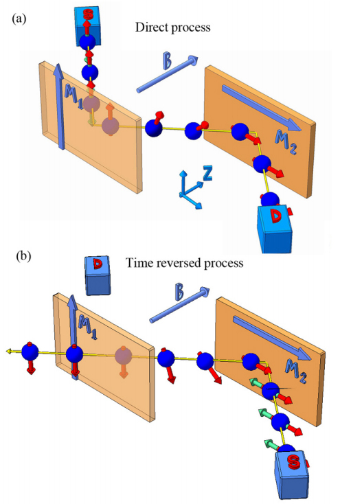
Consider neutrons successively reflected by two ideal mirrors placed in an external magnetic field (see Fig. 1). When the external magnetic field is perpendicular to the mirrors magnetizations the transmission amplitude is expressed as
| (6) |
where and are the reflection amplitudes from the corresponding mirrors and is the Larmour precession in the external field with the corresponding phase. The amplitude of the time-reversed transmission is obtained by replacing of matrices in (6). The intensities of direct and time-reversed transmission are
| (7) |
where is the density matrix of unpolarized neutrons. The transmission in coplanar configuration can be calculated by substituting instead of in (6). The intensities are equal and described by the following expression .
As we have shown above the cause of nonreciprocity is the noncommutativity of the spin 1/2 algebra. This noncommutativity provides the basis for theoretical prediction of persistent electrical currents in mesoscopic magnetic rings with a noncoplanar magnetization distribution Loss et al. (1990); Tatara and Kohno (2003).
III Experiment
The experimental setup is as follows. Two parallel magnetic mirrors were placed in front of each other (see Fig. 2). The mirrors were the CoFe films deposited by magnetron sputtering on glass substrates mm2. The thickness of films is about nm. The coercive force is about 150 Oe and the remanent magnetization is 90-95%. Similar magnetic properties of CoFe films were observed earlier Jung et al. (2003). High quality glass plate of m thickness is placed between the mirrors. The plate controls the intermirror gap and parallelism of the mirrors. The construction is placed in the perpendicular weak homogeneous field induced by two equal magnetic coils. The lateral sizes of the coils are mm3 and the external field varies in range 10-30 Oe. The external field is weak, so we can neglect the Zeeman beam-splitting of the reflected neutron beam Felcher et al. (1995); Korneev et al. (1996). Neutrons were emitted from a source S and succesively reflected by the mirrors, as shown in Fig. 2. Glancing angle is 7 mrad. This angle is in the interval between the first and second critical angles for 3-6 Å neutrons due to the corresponding nuclear and magnetic potentials of CoFe films and substrate (glass). The polarization efficiency of the mirror is about 80%. Twice reflected neutrons are registered by a detector D. The neutron source for the experiment is pulsed reactor IBR-2M of Joint Institute for Nuclear Research in Dubna.
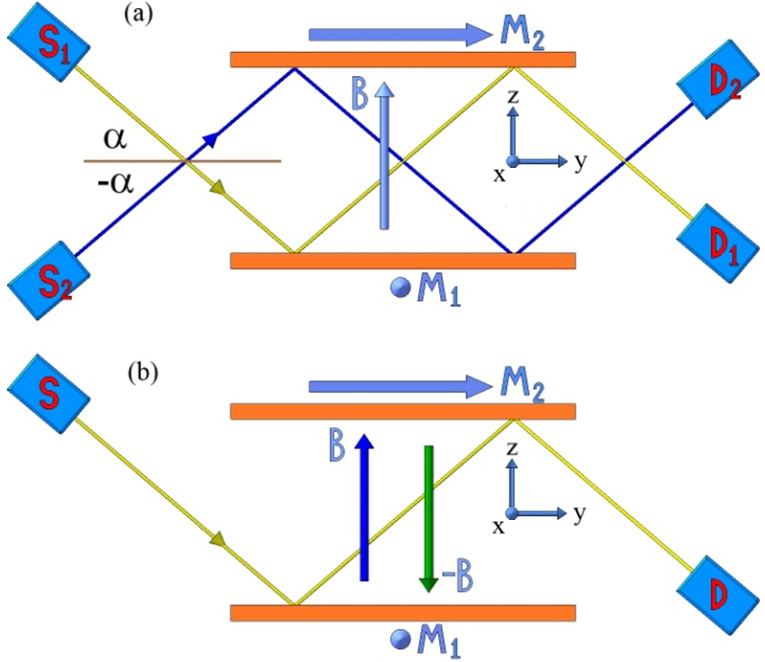
According to definitions in Eqs. (3) and (4) to investigate nonreciprocal effects one needs to measure the intensity of transmitted neutrons before and after the interchange of source and detector. Practically, this means rotation of the entire mirror system as a whole by the angle around the -axis. Such a rotation cannot be performed with a high precision. Therefore we did two types of experiments which are equivalent to measurement with a source-detector interchange.
In the first experiment (see Fig. 2(a)) we measured the transmittivity of neutron beam incident at the angle . The beam was first reflected by bottom mirror and then by the upper mirror. After that we measured the transmittivity of neutron beam incident at angle . In this case the order of reflections was different. We can show that this experiment is equal to transmission for direct and time-reversed processes. Imagine a system where the source and detector are interchanged ( and ). Let us rotate the system as a whole by the angle around the -axis. After such rotation we use the rotational symmetry (5) and rotate only the magnetic fields by the angle around the -axis. These transformations are equal to the changing of sign of the glancing angle (Fig. 2(a)). In the second experiment we measured transmission for fixed source and detector. We did two measurements with different signs of the external magnetic field (see Fig. 2(b)). Using symmetry relations (5) and the reciprocity theorem (2) one can show that this experiment is also equivalent to the measurement of reflectivity for direct and time-reversed processes. We also performed reference experiments with the coplanar system in which magnetizations of both mirrors are along the -axis.
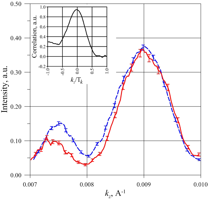
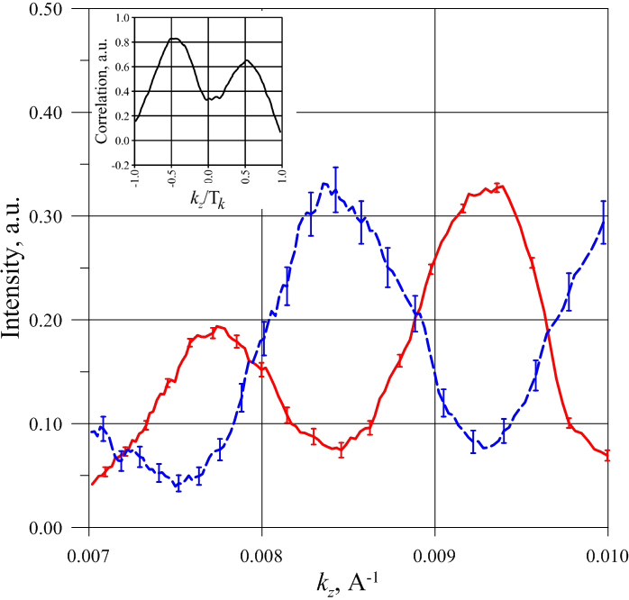
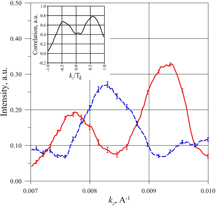
Experimental dependencies of the transmission coefficients on the -component of the wave vector are shown in Fig. 3-6, where , is the neutron wavelength. The common property of these curves is the oscillatory behavior. These oscillations originate from the Larmour precession of the magnetic moment of the neutron in the external field. Indeed, the reflection coefficient of the neutron from the second mirror depends on the relative orientation of its magnetic moment and the magnetization direction of the mirror. The reflection is maximal (minimal) when these magnetic moments are parallel (antiparallel). Taking into account, the fact that after reflection from the first mirror the average neutron magnetic moment is perpendicular to the magnetic moment of the second mirror, the condition for observation of maximum transmission through the system has the form where is the phase of the magnetic moment of the neutron, precessing with a frequency 1sec in the external field during time of flight from the first to the second mirror, cm is the length of the neutron path between mirrors. In our experiment the neutron magnetic moment makes approximately two full turns between the mirrors
| (8) |
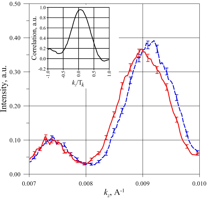
Observation of fundamental difference between direct and time-reverse processes in the case of noncoplanar magnetic field distribution is the main result of our work. In Fig. 3 and 4 the transmittivity at a different glancing angle sings () for coplanar and noncoplanar configurations are shown. Fig. 5 and 6 illustrate the transmissions for inverse external field . For coplanar magnetic field distribution the direct and time-reversed transmissions are actually identical with our experimental accuracy. The experimental precision is determined by several factor: the goniometer accuracy (0.3 mrad), the neutron beam divergence (about 0.6 mrad) and the external field time fluctuations (0.5 Oe per day). For noncoplanar field distribution the situation is completely different: the maximum transmittivity value in direct process corresponds to the minimal transmittivity in reversed process and vice versa. The relative difference in the transmission coefficients of the direct and inverse processes is up to 75% (Fig. 6). We calculate correlation function to analyze difference between direct (red solid lines) and time-reversed (blue dashed lines) reflections Hudson (1969). It is shown on the insets in Fig. 3-6. is the quasiperiod of intensity oscillation. The quasiperiod is calculated for . The correlations for the cases of coplanar and noncoplanar magnetic field distribution are different. For coplanar system the correlation has one maximum near zero. In other words the direct and time-reversed transmissions in coplanar field are equal within the accuracy of our experiment. On the contrary the correlations for noncoplanar field have two maxima near one half of phase period. The intensities of direct and time-reversed processes are counter phased, which suggests that the transmission is nonreciprocal.
IV Discussion
Our experiment is very similar to neutron spin echo (NSE) experiment Mezei (1972). Each magnetic mirror is the boundary with sudden change of the magnetic field because the mirrors’ magnetizations are perpendicular to the external (guide) field. In this respect our mirrors are very much the same as the -flipper of the NSE experiments as in Ref. Mezei (1972). For all parallel magnetizations we have straightforward measurement of NSE oscillations similar to observed in Ref. Mezei (1972). The conventional NSE experiment means that the -flippers have parallel magnetic fields. In the noncoplanar configuration the magnetizations of our mirrors are perpendicular to each other and this is the main difference from NSE experiments.
Besides the considered system is a nonreciprocal cell for neutrons similar to the nonreciprocal Faraday cell for light. Both cells consist of a polarizer, analyzer and a phase shifter. In our case they are the magnetic mirrors and magnetic field in the gap between the mirrors. There is a fundamental difference, though, between our system and the Faraday cell, being in that the fact that photons are bosons. The difference in the transmission intensities in the forward and reverse direction for a Faraday cell is proportional to , and for neutrons cell it is proportional to , where is the angle between the polarizer and analyzer (magnetic moments of the mirrors in the considered case). Note that the nonreciprocal cell, similar to the one studied in our work, can be realized for electrons. The spin precession of electron has been observed experimentally Jedema et al. (2002) by measuring the conductivity of the conductor between the two ferromagnetic electrodes placed in a perpendicular magnetic field. In these experiments the magnetic moments of the ferromagnetic electrodes were parallel or antiparallel and the whole magnetic system was coplanar. If the electrodes were arranged perpendicular to each other, the magnetization distribution in the system could be noncoplanar and nonreciprocal effect can be observed. Such a situation was theoretically considered in Ref. Udalov (2012). A Rectification effect appearing due to non-commutativity of spin algebra was predicted. The essential peculiarity of electrons is that they propagate through the middle layer diffusively. This leads to relaxation of the electron spin at characteristic length and restricts the length of the middle layer .
Acknowledgements.
Authors are grateful to N. Korotkova, B. Gribkov, P. Yunin and N. Gusev for assistance in magnetic mirror preparation and attestation. Also authors are grateful to S. Kozhevnikov, A. Klimov, V. Rogov and I. Shereshevskii for processing the experimental results. Authors thank I. Beloborodov for useful discussion of the results. This work was supported by The Ministry of education and science of the Russian Federation projects and grants: 3.2054.2014/K, 11.G34.31.0029 and 02.B.49.21.0003. The research was supported by RFBR Grant 14-02-31809 and 14-02-00625.References
- Pulizzi (2012) F. Pulizzi, Nat Mater 11, 367 (2012).
- Baibich et al. (1988) M. Baibich, J. Broto, A. Fert, F. Van Dau, F. Petroff, P. Etienne, G. Creuzet, A. Friederich, and J. Chazelas, Phys. Rev. Lett. 61, 2472 (1988).
- Binasch et al. (1989) G. Binasch, P. Grünberg, F. Saurenbach, and W. Zinn, Phys. Rev. B 39, 4828 (1989).
- Aharonov and Stern (1992) Y. Aharonov and A. Stern, Phys. Rev. Lett. 69, 3593 (1992).
- Li et al. (2013) Y. Li, N. Kanazawa, X. Z. Yu, A. Tsukazaki, M. Kawasaki, M. Ichikawa, X. F. Jin, F. Kagawa, and Y. Tokura, Phys. Rev. Lett. 110, 117202 (2013).
- Berger (1996) L. Berger, Phys. Rev. B 54, 9353 (1996).
- Slonczewski (1996) J. Slonczewski, Journal of Magnetism and Magnetic Materials 159, L1 (1996).
- Zhang and Li (2004) S. Zhang and Z. Li, Phys. Rev. Lett. 93, 127204 (2004).
- Izyumov et al. (1991) I. Izyumov, V. Naish, and R. Ozerov, Neutron diffraction of magnetic materials (Consultants Bureau, 1991).
- Ignatovich (1978) V. Ignatovich, JETP Lett. 28, 311 (1978).
- Felcher et al. (1995) G. P. Felcher, S. Adenwalla, V. O. D. Haan, and A. A. V. Well, Nature 377, 409 (1995).
- Korneev et al. (1996) D. Korneev, V. Bodnarchuk, and K. Ignatovich, Journal of Experimental and Theoretical Physics Letters 63, 944 (1996).
- Mezei (1972) F. Mezei, Zeitschrift für Physik 255, 146 (1972).
- Landau and Lifshitz (1977) L. Landau and E. Lifshitz, Quantum Mechanics: Non-Relativistic Theory, Teoreticheskai︠a︡ fizika (Elsevier Science, 1977).
- Deák and Fülöp (2012) L. Deák and T. Fülöp, Annals of Physics 327, 1050 (2012).
- Shelankov and Pikus (1992) A. L. Shelankov and G. E. Pikus, Phys. Rev. B 46, 3326 (1992).
- Udalov (2012) O. G. Udalov, SPIN 02, 1250013 (2012).
- Udalov and Fraerman (2014) O. G. Udalov and A. A. Fraerman, Phys. Rev. B 90, 064202 (2014).
- Tatara and Kohno (2003) G. Tatara and H. Kohno, Phys. Rev. B 67, 113316 (2003).
- Fraerman and Udalov (2008) A. A. Fraerman and O. G. Udalov, Phys. Rev. B 77, 094401 (2008).
- Tatarskiy et al. (2012) D. Tatarskiy, O. Udalov, and A. Fraerman, Journal of Experimental and Theoretical Physics 115, 626 (2012).
- Loss et al. (1990) D. Loss, P. Goldbart, and A. V. Balatsky, Phys. Rev. Lett. 65, 1655 (1990).
- Jung et al. (2003) H. S. Jung, W. D. Doyle, and S. Matsunuma, Journal of Applied Physics 93 (2003).
- Hudson (1969) D. Hudson, Lectures on Elementary Statistics and Probability (CERN, 1969).
- Jedema et al. (2002) F. J. Jedema, H. B. Heersche, A. T. Filip, J. J. A. Baselmans, and B. J. van Wees, Nature 416, 713 (2002).