Fragmentation processes in two-phase materials
Abstract
We investigate the fragmentation process of solid materials with crystalline and amorphous phases using the discrete element method. Damage initiates inside spherical samples above the contact zone in a region where the circumferential stress field is tensile. Cracks initiated in this region grow to form meridional planes. If the collision energy exceeds a critical value which depends on the material’s internal structure, cracks reach the sample surface resulting in fragmentation. We show that this primary fragmentation mechanism is very robust with respect to the internal structure of the material. For all configurations, a sharp transition from the damage to the fragmentation regime is observed, with smaller critical collision energies for crystalline samples. The mass distribution of the fragments follows a power law for small fragments with an exponent that is characteristic for the branching merging process of unstable cracks. Moreover this exponent depends only on the dimensionally of the system and not on the micro structure.
pacs:
46.50.+a, 62.20.M-, 81.40.Np, 05.10.-a, 62.20.mmI Introduction
Multiphase materials, which are composed of different homogeneous phases, are abundant in nature and constitute basic raw ingredients for many industrial processes. Comminution is an important and energy-intensive process where various physical principles are applied to fragment multiphase material down to a powder. Grinding of clinker to produce the major component in Portland cement and thus the binder in concrete Mander et al. (1988); Flatt et al. (2012) is an example of a process which consumes a significant portion of the energy consumed by mankind. Clinker is the product of calcination of a mixture of co-grinded minerals (80%) and clays (20%). The blended compound is a complex mineral product composed of at least four principal mineral phases , , , , (in cement chemist notation) Aïtcin (2000). The first two phases (Alite (50-65%) and Belite (10-20%) are crystalline, with the rest being amorphous. Several improvements have been conceived Flatt et al. (2012) in order to boost the efficiency of the comminution process. In particular fragmentation studies have shown the potential to substantially reduce the energy consumption of the overall cement production Misra and Cheung (1999); Cleary et al. (2008).
In the past, statistical models and corresponding simulation schemes have been developed to systematically investigate brittle fragmentation Åström (2006); Herrmann et al. (1989); Kun and Herrmann (1999); Diehl et al. (2000); Araripe et al. (2005a, b) in terms of the resulting fragment size distribution, crack merging and propagation, instability and branching, and the occurrence of damage transition. Simulations based on Lennard-Jones (MD) systems, continuum-, elastic element-, beam- and lattice models have been able to reproduce quite nicely the observed behavior. However for the sake of simplicity and to increase computational efficiency, most fragmentation simulations only consider single-phase materials. In this work we address the brittle fragmentation process of multiphase materials considering the simplest case of two-phase materials, where a crystalline elastic phase is embedded in an amorphous elastic matrix. The non-isotropic structure of the crystalline phase is taken into account explicitly through a hexagonal close packing (hcp) lattice. During comminution, the material is reduced from macroscopic granules to a microscopic powder. We will then compare fragmentation of purely crystalline and amorphous samples with the bi-phase ones throughout this study to explore the effect of texture.
This paper is organized as follows. In Sec. II we describe the model used in this work, explaining how multiple phases are introduced in conjunction with the Discrete Element Model scheme. In Sec. III results for impact simulations for amorphous, crystalline and two-phase materials are presented and the occurrence of different fragmentation mechanisms, fragmentation regimes and resulting fragment mass distributions are analysed. Finally in Sec. IV we present the conclusions and perspective of future work.
II Model description
The most successful numerical approaches to dynamic fragmentation so far are based on the discrete-element model (DEM) Cundall and Strack (1979). This type of technique has been largely used for the simulation of ball mills Mishra and Rajamani (1992); Cleary (2004); Weerasekara et al. (2013), shear flow Lätzel et al. (2000); Iwashita and Oda (2000); Eggersdorfer et al. (2010); Kamrin and Koval (2012), compaction Grof and Stepanek (2013), and fracture of materials Potapov and Campbell (1996); Kun and Herrmann (1999); Wittel et al. (2005); Carmona et al. (2007); Timár et al. (2010, 2012); Asahina and Bolander (2011); Affes et al. (2012), among numerous other applications with particles of various shapes and diverse cohesive elements. The three-dimensional DEM used in this work Carmona et al. (2008) discretizes the material by an assembly of spherical elements with different sizes. For calculating a repulsive Hertzian contact force as an elastic interaction, a finite stiffness is assigned, so that two particles are allowed to overlap slightly. Particles are bonded by cylindrical beam-truss elements that may deform by elongation, bending and torsion, producing bond forces and moments on the corresponding particle centers. A detailed description of the force computation (normal, shear and damping forces and moments), as well as the 3D representation of the beam-truss elements used in this work can be found in Refs. Pöschel and Schwager (2005); Carmona et al. (2008). The time evolution of the system, namely translation and rotation of each particle, is followed numerically by solving Newton’s equation of motion through explicit numerical integration with a time increment Carmona et al. (2008). Dynamic fracturing of the material is incorporated into the model through the sequential failure of beam-truss elements. Beams are removed once their elliptical breaking rule Kun and Herrmann (1996a, b); Herrmann et al. (1989); Carmona et al. (2008) based on the von Mises criterion type Herrmann et al. (1989)
is fulfilled, where is the longitudinal strain and and are the general rotation angles at the ends of the beam connecting particle with , respectively. The threshold values, and , are sampled from a Weibull distribution Weibull (1951); Carmona et al. (2008), introducing quenched disorder in the system. The beam breaking mechanism is irreversible in the sense that broken beams are excluded from the force calculations for all consecutive time steps. The macroscopic strength of the material can be tuned by adopting the average breaking threshold and the amount of disorder in each material phase separately.
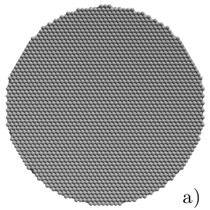
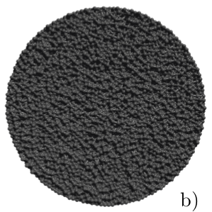
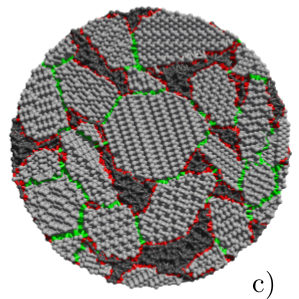
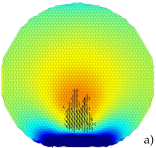
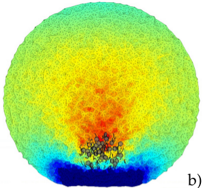
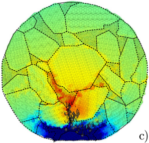
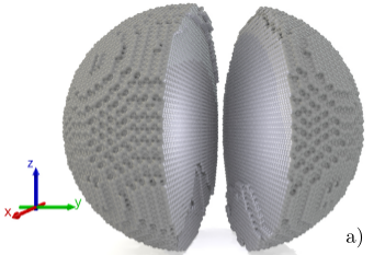
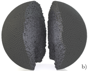
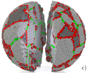
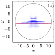
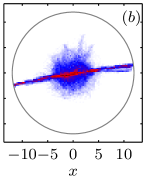
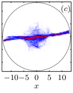
For comparison, here three different types of samples are defined as shown in Fig. 1. In the case of type I, crystalline samples are generated by placing all elements in a hexagonal close packing (hcp) regular lattice. Nearest neighbors are connected by beam-truss elements. A spherical sample (see Fig.1(a)) is obtained by trimming all elements and beams outside the desired spherical region. The samples of type II are amorphous solids generated by positioning particles randomly in a spherical region and connecting them using a three-dimensional Voronoi tessellation (see Fig.1(b)). The randomization of the initial configuration is achieved by first placing elements on a hcp lattice, assigning initial random velocities and letting the system evolve. A spherical, slowly shrinking confinement is used to obtain a randomly packed spherical system. Type III samples are multiphase ones and their generation follows a more complicated procedure. Initially a packing of random convex polyhedra of a desired size and shape distribution is generated, as described in Appendix A. A hcp particle packing is inserted in every polyhedron with the respective local crystal coordinate system and connected like in the method to form crystallites. In a next step particles are placed in the interstitial spaces between polyhedra. Random velocities are assigned to all particles and the system evolves inside a spherical confinement again, until the newly added particles accommodate in the regions between the crystallites. The diameter of the confining sphere is then slowly decreased and the system is cooled by adding a small viscous force to all elements. The resulting system has ordered hcp crystals and random regions as shown in Fig.1(c). Finally all particles are connected by beams again using Voronoi tessellation.
Bonds connecting amorphous to crystalline particles are labeled amorphous-crystalline interface, while those connecting different crystallites are labeled inter-crystalline interface and may also be given different material properties. The final multiphase sample used in the simulations performed here has a total of 46 crystallites embedded in an amorphous phase matrix occupying a volume fraction 0.2. The average number of elements and bonds in the crystallites is 806 and 6429, respectively.
 |
 |
 |
III Impact simulations
Single particle impact fragmentation against a rigid target is among the most studied fragmentation scenarios both from the experimental and theoretical perspective Antonyuk et al. (2006); Inaoka and Ohno (2003); Salman et al. (2002); Timár et al. (2012). For the sake of comparison, we limit ourselves to this case and simulate impacts of various collision energies for the three distinct configurations. The microscopic properties, namely the elastic properties of the elements and bonds, as well as the bond breaking thresholds can be chosen to attain the desired macroscopic stiffness and tensile strength of the respective phases. In this work all beams are assigned identical elastic properties so that we focus mainly on the consequence of the underlying micro-structure. Table 1 summarizes all input values used in the simulations.
| Beams | |||
|---|---|---|---|
| stiffness | 6.0 | GPa | |
| average length | 0.5/0.53/0.61 | mm | |
| cross section diameter | 0.5 | mm | |
| strain threshold | 0.02 | ||
| bending threshold | 3.5 | ∘ | |
| Weibull shape parameter | 10 | ||
| Spherical elements | |||
| stiffness | 3.0 | GPa | |
| diameter | 0.5 | mm | |
| density | 3000 | ||
| Hard plate | |||
| stiffness | 1000 | GPa | |
| Interaction | |||
| friction coefficient | 1 | ||
| Damping coefficient | 0.0001 | kg/s | |
| friction coefficient | 0.0001 | kg/s | |
| System | |||
| number of elements | |||
| number of beams | |||
| sphere diameter | 12/12/13.4 | mm | |
III.1 Fragmentation mechanisms
We performed a series of numerical impact simulations of spherical samples against a wall of stiffness . As the impactor contacts the target, it begins to deform due to repulsive contact forces. As a result, a ring of broken bonds forms due to shear failure in the contact region. At the same time diffuse damage appears around this region. It can be seen from Fig. 2 that there is a strong correlation between the position of the diffuse damage region and the region where the circumferential stress in the plane perpendicular to the impact direction is tensile. In this zone, the biaxial stress state is superimposed by a compression in impact direction. This mechanism was reported both experimentally and numerically for single phase materials Andrews and Kim (1998); Carmona et al. (2008). As the fracture evolves, cracks initiated in the biaxial stress state region develop to form meridional cracks. If the collision energy is large enough, these cracks propagate through the material forming crack planes that reach the sample surface resulting in fragmentation. Although for multiphase samples the stress field is more heterogeneous, due to the long range correlated disorder imposed by the different crystallites, the crack formation mechanism described above is quite robust, resulting in meridional cracks in all three types of samples.
 |
 |
 |
The morphology of the cracks depends strongly on the texture. For crystalline samples, cracks propagate along well defined cleavage planes of the hcp lattice. In the amorphous samples there are no preferential orientations, but still cracks form meridional crack planes, cutting the sample into wedge-shaped fragments Carmona et al. (2008). For multiphase samples with the more heterogeneous stress field, meridional cracks still propagate from the biaxial stress state region to the sample surface leading to the fragmentation of the sample. These cracks cut through cleavage planes in the crystalline particles of the multiphase sample, and typically along fixed directions through the amorphous phase. This results in a more complicated crack morphology.
III.2 Fragmentation regimes
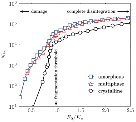
Depending on the collision energy, impact not necessarily results in fragmentation. We average over 30 realizations for each energy, where fracture thresholds of individual runs are randomly sampled from the Weibull distribution Carmona et al. (2008). The sizes of the final fragments depend on the collision energy and the internal structure of the sample. In Fig. 3 the ensemble average of the mass of the largest fragment, , normalized by the initial mass of the system is plotted as a function of the collision energy , for the three different microstructures. The mass averaged of the other fragments, defined by , where with being the total number of fragments, is also shown as a function of in the inset of Fig. 3.
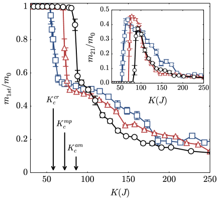
It is evident that in all three cases a collision energy exists, below which the mass of the largest fragment corresponds to nearly the mass of the whole system. This characterizes the damage regime as opposed to the fragmentation regime, where the mass of the largest fragment is less than half the sample mass. The transition from the damage regime to the fragmentation regime occurs in a narrow energy interval, in which a fraction of the samples fragment, while in the remaining only damage occurs. We observe that in the narrow transition interval of energy the damaged samples usually present a large crack. However, fragmentation is prevented because the collision energy is not enough for this crack to reach the sample’s surface. For individual samples in the ensemble, the transition from damage to fragmentation occur more abruptly
We define the critical collision energy for each type of sample as the energy at which the variation of the ensemble averaged mass of the largest fragment is a maximum. The critical collision energy for the crystalline samples is found to be J. However this value depends strongly on the orientation of the sample lattice with respect to the impact direction. Note that, in the results reported here, a cleavage plane contains the impact velocity vector. For multiphase samples J, this value also depends on the sample orientation, being smaller when there are crystalline grains in the region where cracks originate having cleave planes with normal perpendicular to the impact velocity vector. For amorphous samples the critical energy has the highest value of J.
At the mass of largest fragment and the average mass of all other fragments are each approximately half the initial mass of the system, indicating that, at this energy value, one of the meridional cracks reaches the surface of the sample cutting it into two large fragments and a few smaller ones. Above the critical energy, the sample disintegrates into smaller fragments. We can observe that the mass of the largest fragment and the average mass decay slower as a function of for the case of crystalline and multiphase samples as compared to the amorphous ones. This is because the lattice anisotropy prevents cracks from propagating in the preferred direction, consequently hindering further fragmentation of larger fragments by secondary mechanisms. The smaller critical energy for crystalline samples is also a consequence of the anisotropy of the crystalline structure which favors the growth along well defined cleavage planes. This effect can be clearly seen in Fig. 4 when comparing the number of broken bonds at the critical collision energy and hence the total dissipated energy. As can be expected, multiphase samples also show this effect with crack growth along cleavage planes in crystallites, but to a much smaller extent.
The orientation of the resulting crack planes at the critical energy is explored further in Figs. 5 and 6. Figure 5 pictures the two largest fragments resulting from typical impact simulations with the critical energy for each of the three types of material. Figure 6 shows the corresponding two-dimensional histograms of the number of broken bonds for the same simulations. All three samples show uncorrelated bond breaking close to the origin that corresponds to the damage in the biaxial stress zone at the beginning of the fragmentation process. At the final stage, well defined diametrical planes are observed for all configurations, however the one of the crystalline sample is the sharpest one, corresponding to a cleavage plane of the hcp lattice. We see that, even for the multiphase microstructure, the final crack grows along a well defined diametrical plane. Once a crack is formed in the diffuse region at the beginning of the fragmentation process, it does not change its direction until reaching the surface. Note that the amorphous sample exhibits more uncorrelated cracks near the impact axis than the others.
 |
 |
 |
 |
 |
 |
As the collision energy is increased, more meridional cracks are formed. Azimuthal cracks, namely, cracks perpendicular to the impact axis, also appear breaking fragments even further, in what constitutes a secondary fragmentation mechanism. These cracks start in a thin region, where the stress in the direction of the impact axis is tensile due to bending of the wedge shaped fragments, and concentrate near the contact disk. Oblique cracks also appear due to complex stress state that originates when the particle is already broken into wedge-shaped fragments.
III.3 Fragment mass distribution
For a more detailed analysis, the fragment mass distribution at the critical energy is plotted in Fig. 7. Again values are averaged over 30 realizations for each type of sample and each collision energy. The fragment mass distribution is surprisingly similar for all three microstructures. At the critical collision energy, shows a peak for large fragments at about half the initial system mass. This corresponds to the sample breaking into two large fragments as described above. For fragments with typically less than one percent of the system mass, follows a power law, , with exponent .
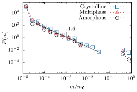
This power law extends for , as can be observed in Fig. 8, where the fragment mass distributions for J are plotted for the three types of samples. Surprisingly, at this high collision energy value, the obtained mass distributions of fragments are very similar for the three types of samples. This result suggests that, at this point, the energy is so distant from the critical collision energy that the particular fragmentation mechanisms causing the differences in for each type of sample are not so relevant. At this high collision energy, the fragment mass distribution exhibits more clearly the power-law behavior for small fragments.
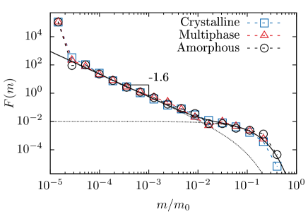
As we can see from Figs. 7 and 8, the fragment mass distribution is independent of the internal material structure within our statistical errors and can be described at high collision energy by the expression,
| (1) |
This functional form has been proposed by Åström et al Åström et al. (2004); Åström (2006) and has been successfully applied to describe results both experimental and numerical results.
The first term in Eq.(1) is related to the branching and merging process of unstable cracks. The second term originates from the Poissonian nucleation process of dominating cracks, in our case, the meridional cracks nucleated in the beginning of the fragmentation process.
IV Conclusions
To reveal the role of the internal microstructure in the fragmentation process, we compare impact fragmentation of spheres made of pure phases with multiphase ones. We employed 3D beam-truss cohesion elements with identical elastic properties for all phases. A transition from a damaged state to a fragmented state is observed as the collision energy is increased. Crystalline samples tend to fragment at a smaller collision energy if there is a cleaveage plane that contains the impact direction. In this case, the dominant fracture crack corresponds to a cleavage plane of the crystal. For multiphase material, the dominant crack cleaves the crystallites and cuts through the embedding amorphous phase without changing direction. The amorphous samples require the largest fragmentation energy.
We found that the dominant fragmentation mechanism is related to cracks that form inside the material due to tensile radial and circumferential stress in the ring-shaped region above the contact plane. These cracks grow to give rise to meridional fracture planes that result in a small number of large fragments. Even though the stress distribution is more inhomogeneous in the multiphase material, this dominant fragmentation mechanism was found to be independent of the internal structure of the material. As a result, the final mass distribution of the fragments is independent of the material structure. It presents a power-law regime for small fragments and a broad exponential region for large fragments. The fragment mass distribution can be successfully explained in terms of the branching and merging processes of unstable cracks and the Poissonian initiation process for the dominant cracks.
The influence on fragmentation of the size and shape dispersion of the crystalline particles, as well as the importance of the elastic properties of each phase, in multiphase materials give rise to interesting questions. The ability of the model to reproduce the complex stress state and crack planes with well defined cleavage planes in the crystalline regions opens up the possibility to study further crack propagation problems in multiphase materials. Extensions to different material properties for different phases and detailed studies on the influence of size dispersion are in progress.
V Acknowledgments
We thank the Brazilian Agencies CNPq, CAPES and FUNCAP for financial support. We acknowledge support by the Swiss Commission for Technological Innovation under grant no. KTI 13703.1 PFFLR-IW and the European Research Council through Grant FlowCSS No. FP7- 319968 for financial support. I.N. acknowledges support by the Alexander S. Onassis Public Benefit Foundation from Greece. We are also grateful for fruitful discussions with E. Gallucci and M. Weibel from Sika Technology AG, as well as R. J. Flatt and R. K. Mishra.
References
- Mander et al. (1988) J. B. Mander, M. J. N. Priestley, and R. Park, J. Struct. Eng.-ASCE 114, 1804 (1988).
- Flatt et al. (2012) R. J. Flatt, N. Roussel, and C. R. Cheeseman, J. Eur. Ceram. Soc. 32, 2787 (2012).
- Aïtcin (2000) P.-C. Aïtcin, Cem. Concr. Res. 30, 1349 (2000).
- Misra and Cheung (1999) A. Misra and J. Cheung, Powder Technol. 105, 222 (1999).
- Cleary et al. (2008) P. W. Cleary, M. D. Sinnott, and R. D. Morrison, Int. J. Numer. Methods Fluids 58, 319 (2008).
- Åström (2006) J. A. Åström, Adv. Phys. 55, 247 (2006).
- Herrmann et al. (1989) H. J. Herrmann, A. Hansen, and S. Roux, Phys. Rev. B 39, 637 (1989).
- Kun and Herrmann (1999) F. Kun and H. J. Herrmann, Phys. Rev. E 59, 2623 (1999).
- Diehl et al. (2000) A. Diehl, H. A. Carmona, L. E. Araripe, J. S. Andrade, and G. A. Farias, Phys. Rev. E 62, 4742 (2000).
- Araripe et al. (2005a) L. E. Araripe, J. S. Andrade, and R. N. Costa Filho, Phys. Rev. E 71, 036119 (2005a).
- Araripe et al. (2005b) L. E. Araripe, A. Diehl, J. S. Andrade, and R. N. Costa, Int. J. Mod. Phys. C 16, 253 (2005b).
- Cundall and Strack (1979) P. A. Cundall and O. D. L. Strack, Geotechnique 29, 47 (1979).
- Mishra and Rajamani (1992) B. Mishra and R. K. Rajamani, Applied. Math. Model. 16, 598 (1992).
- Cleary (2004) P. W. Cleary, Eng. Computation 21, 169 (2004).
- Weerasekara et al. (2013) N. S. Weerasekara, M. S. Powell, P. W. Cleary, L. M. T. M. Evertsson, R. D. Morrison, J. Quist, and R. M. Carvalho, Powder Technol. 248, 3 (2013).
- Lätzel et al. (2000) M. Lätzel, S. Luding, and H. J. Herrmann, Granul. Matter 2, 123 (2000).
- Iwashita and Oda (2000) K. Iwashita and M. Oda, Powder Technol. 109, 192 (2000).
- Eggersdorfer et al. (2010) M. L. Eggersdorfer, D. Kadau, H. J. Herrmann, and S. E. Pratsinis, J. Colloid Interface Sci. 342, 261 (2010).
- Kamrin and Koval (2012) K. Kamrin and G. Koval, Phys. Rev. Lett. 108, 178301 (2012).
- Grof and Stepanek (2013) Z. Grof and F. Stepanek, Phys. Rev. E 88, 012205 (2013).
- Potapov and Campbell (1996) A. V. Potapov and C. S. Campbell, Int. J. Mod. Phys. C 7, 717 (1996).
- Wittel et al. (2005) F. K. Wittel, F. Kun, H. J. Herrmann, and B. H. Kröplin, Phys. Rev. E 71, 016108 (2005).
- Carmona et al. (2007) H. A. Carmona, F. Kun, J. S. Andrade, and H. J. Herrmann, Phys. Rev. E 75, 046115 (2007).
- Timár et al. (2010) G. Timár, J. Blömer, F. Kun, and H. J. Herrmann, Phys. Rev. Lett. 104, 095502 (2010).
- Timár et al. (2012) G. Timár, F. Kun, H. A. Carmona, and H. J. Herrmann, Phys. Rev. E 86, 016113 (2012).
- Asahina and Bolander (2011) D. Asahina and J. E. Bolander, Powder Technol. 213, 92 (2011).
- Affes et al. (2012) R. Affes, J. Y. Delenne, Y. Monerie, F. Radjai, and V. Topin, Eur. Phys. J. E 35 (2012).
- Carmona et al. (2008) H. A. Carmona, F. K. Wittel, F. Kun, and H. J. Herrmann, Phys. Rev. E 77, 051302 (2008).
- Pöschel and Schwager (2005) T. Pöschel and T. Schwager, Computational Granular Dynamics : Models and Algorithms (Springer-Verlag Berlin Heidelberg New York, 2005).
- Kun and Herrmann (1996a) F. Kun and H. J. Herrmann, Comput. Meth. Appl. Mech. Eng. 138, 3 (1996a).
- Kun and Herrmann (1996b) F. Kun and H. J. Herrmann, Int. J. Mod. Phys. C 7, 837 (1996b).
- Weibull (1951) W. Weibull, J. Appl. Mech. T. ASME 18, 293 (1951).
- Antonyuk et al. (2006) S. Antonyuk, M. Khanal, J. Tomas, S. Heinrich, and L. Morl, Chem. Eng. Process. 45, 838 (2006).
- Inaoka and Ohno (2003) H. Inaoka and M. Ohno, Fractals 11, 369 (2003).
- Salman et al. (2002) A. D. Salman, C. A. Biggs, J. Fu, I. Angyal, M. Szabo, and M. J. Hounslow, Powder Technol. 128, 36 (2002).
- Andrews and Kim (1998) E. W. Andrews and K. S. Kim, Mech. Mater. 29, 161 (1998).
- Åström et al. (2004) J. A. Åström, R. P. Linna, J. Timonen, P. F. Moller, and L. Oddershede, Phys. Rev. E 70, 026104 (2004).
- Nikolakopoulos (2013) I. Nikolakopoulos, Clinker Simulation, Master’s thesis, Swiss Federal Institute of Technology (ETH Zurich) (2013).
- Gonzalez et al. (2003) R. C. Gonzalez, R. E. Woods, and S. L. Eddins, Digital Image Processing Using MATLAB (Prentice-Hall, Inc., Upper Saddle River, NJ, USA, 2003).
- OhserOhser and Mücklich (2000) J. OhserOhser and F. Mücklich, Statistical Analysis of Microstructures (John Wiley & Sons, Ltd, 2000).
- Jagnow et al. (2004) R. Jagnow, J. Dorsey, and H. Rushmeier, ACM Trans. Graph. 23, 329 (2004).
- Mishra (2012) R. K. Mishra, Simulation of Interfaces in Construction Materials: Tricalcium Silicate, Gypsum, and Organic Modifiers, Ph.D. thesis, University of Akron, Polymer Engineering (2012).
- Legland (2009) D. Legland, “geom3d,” http://www.mathworks.com/matlabcentral/fileexchange/24484 (2009).
- D’Errico (2012) J. D’Errico, “Inhull,” http://www.mathworks.com/matlabcentral/fileexchange/10226-inhull (2012).
Appendix A Construction of multiphase sample
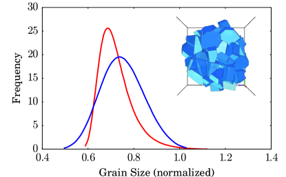
The grain size distribution of a crystallic phase is a prerequisite for every microstructural simulation. Under grain size the max caliper diameter of a convex grain is understood. Based on two-dimensional micrographs Nikolakopoulos (2013), the grain size distribution of the two-dimensional cross-sections of the grains can be recovered by means of a boundary-tracking method Gonzalez et al. (2003). After making certain simplifying assumptions regarding the grains’ shape, stereological considerations allow one to estimate the three-dimensional grain size distribution OhserOhser and Mücklich (2000); Jagnow et al. (2004). The grain shape in our case is an irregular convex polyhedron, which renders most of the relatively simple stereological techniques impractical. For this reason, the assumption of a spherical shape is adopted and the problem reduces to determining the size distribution of a polydisperse system of spherical particles. More details on the computation of the 3D distribution estimate can be found in Jagnow et al. (2004).
The generation of the sample starts by producing a shape-pool composed of individually evolved instances of one or several reference grain shapes. For simplicity only one phase is considered in the presentation, since other crystallic phases are straightforward to incorporate. The original shape could be, for instance, a possible equilibrium shape of a crystallic phase, whose Miller indices are estimated based on the directional cleavage energies Mishra (2012). Grains are picked from this pool in a way that their sizes follow the previously estimated grain size distribution and are placed into a confining spherical volume at random positions but without overlap. After the desired number of grains is in place, the size distribution constraint is already satisfied and the shapes encode all the information regarding the crystal structure of the phase. It then boils down to achieving a realistic volume fraction for this phase while distorting its original characteristics as little as possible. To this end, a simple packing algorithm is applied, making use of the libraries Legland (2009); D’Errico (2012). For a sufficiently large number of steps, a grain is chosen at random and the following transformations are applied to it: (i) random translation in the range , (ii) random rotation around each axis, within the interval and (iii) with probability close to , a random translation within towards the center of the spherical confining volume (radial translation). The move is only accepted if the new position does not lead to an overlap, otherwise it is rejected and a new random grain is chosen.
Since randomly shaped polyhedra are not expected to efficiently fill the space, further action needs to be taken for a high packing density to be reached. An expand-and-clip strategy is introduced, which targets high volume fraction at the cost of an arbitrary (but small) shape deformation. All grains are expanded via in-place scaling, controlled by a single scaling factor, which results in a configuration with all grain centroids retaining their previous positions, while arbitrary overlaps between grains occur. The non-overlap constraint is recovered by clipping all pairs of overlapping grains with the plane that (i) has normal parallel to the line connecting the centroids of the two involved grains and (ii) the centroid of the convex polyhedron that forms their intersection lies on it. Using the aforementioned procedure, a system of 100 grains was initialized with the prescribed size distribution. After packing with , and clipping with scaling factor , a volume fraction of approximately 78% was achieved. The quality of the final sample was determined by (i) comparison of its cross-sections with the available micrographic data and (ii) visual inspection of the distortion of the original grain size distribution (see Fig. 9). The sample was deemed reliable, i.e. a possible occurrence of a granular configuration in a multiphase material.