Ion beam requirements for fast ignition of inertial fusion targets
Abstract
Ion beam requirements for fast ignition are investigated by numerical simulation taking into account new effects such as ion beam divergence not included before. We assume that ions are generated by the TNSA scheme in a curved foil placed inside a re-entrant cone and focused on the cone apex or beyond. From the focusing point to the compressed core ions propagate with a given divergence angle. Ignition energies are obtained for two compressed fuel configurations heated by proton and carbon ion beams. The dependence of the ignition energies on the beam divergence angle and on the position of the ion beam focusing point have been analyzed. Comparison between TNSA and quasi-monoenergetic ions is also shown.
pacs:
52.38.Kd, 52.65.Ww, 52.57.KkI Introduction
Fast ignition (FI) was proposed 20 years ago as an alternative to the standard central ignition scheme of inertial fusion targets Tabak1994 . It intends to reduce the drive requirements by separating fuel compression and ignition. In electron-driven fast ignition (EFI), a fast electron jet generated by ultra-high intensity lasers triggers ignition of the thermonuclear fuel. Due to the very large divergences and the too high kinetic energies found in EFI experiments and simulations Kemp2014 ; Robinson2014 , ion-driven fast ignition (IFI) has been taking an increasing interest over the last years. Ion fast ignition Tabak1998 ; Roth2001 offers several advantages over EFI, such as generation of collimated beams, well known interaction with the plasma and higher flexibility. Some examples of such a flexibility are the control of ion spectra Fernandez2014 ; Weng2014 , the possibility of choosing the optimal ion species Albright2008 ; Honrubia2014 , including deuterium ions Liu2011 , and the use of multiple beams for target irradiation Temporal2006 ; Temporal2008 ; Honrubia2014 . IFI progress so far can be summarized by the experimental achievement of the required ion energies, high conversion efficiencies Brenner2014 and ion beam focusing Bartal2012 . This last achievement is crucial because it points a way forward to get beam focusing into the 30-40 m spots required for IFI. A full review of the current status of IFI can be found in Ref. Fernandez2014 .
Just after the first experimental evidence of proton acceleration by the Target Normal Sheath Acceleration (TNSA) mechanism Snavely2000 , its application to FI was proposed Roth2001 . This was followed by theoretical studies on the TNSA scheme Mora2003 ; Murakami2006 , target studies Hatchett2000 ; Atzeni2002 ; Temporal2002 ; Ramis2004 , new irradiation schemes Temporal2006 ; Temporal2008 ; Honrubia2014 and the use of ions heavier than protons Fernandez2009 ; Honrubia2009 . Other schemes such as the two-pulse scheme described in Ref. Tikhon2010 have been proposed also. This scheme consists of creating a plasma channel followed by Deuterium-Tritium (DT) acceleration close to the dense core. Hole boring scalings have been studied recently in Ref. Murakami2012 .
Most of the ignition studies carried out so far are based on rather ideal target configurations and simplified ion interaction models. For instance, these models do not take into account cone tip and coronal plasma energy deposition nor scattering of the beam ions in the hot plasma between the cone tip and the dense core.
Fully integrated numerical modeling of the IFI scheme, from beam generation to fuel ignition, is not possible today with the present computer resources. It requires the integration of physical processes with very different spatial and temporal scales. In this paper, we use a simplified model that assumes an ideal initial distribution function of ions and computes ion energy deposition by solving the Fokker-Planck equation. Specifically, we assume that a highly uniform laser beam, required to improve the ion beam focusing Foord2012 , with irradiances of the order of W/cm2 impinges on a curved foil placed inside a cone, generating a proton or carbon ion beam at the foil rear surface by means of the TNSA scheme Key2006 . Ions are focused into the inner surface of the cone tip or beyond by the electrostatic fields generated near the cone walls. From the beam focusing point, ions diverge towards the dense fuel. This paper deals with determining the beam requirements to ignite a target as a function of the ion beam divergence taking into account the ion interactions with the cone tip and their scattering with the background plasma ions. The goal has been to obtain realistic estimates of the ignition energies in the IFI scenario.
This paper is organized as follows. In Section II, the computational model used in the simulations is briefly outlined. Details of the multidimensional Fokker-Planck ion energy deposition model and its differences with the standard ion tracking scheme are shown. In Section III, ion energy deposition and scattering by the cone tip, energy deposition of divergent beams in the DT core, ignition energies of proton and carbon ions with maxwellian and quasi-monoenergetic energy distributions, and the effect of the position of the beam focusing point are presented. Finally, conclusions and future work are summarized in Section IV.
II Simulation model
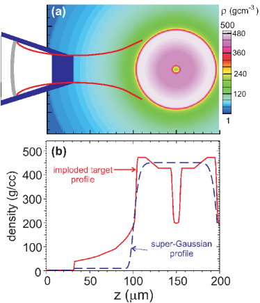
We assume a uniform (constant flux within its cross section) ion beam impinging on a compressed DT fuel. The beam is generated by the TNSA scheme Snavely2000 , which yields ions with a maxwellian energy distribution. In order to reduce the ion time spread along the stand-off distance from the generation foil to the dense fuel, we assume that a re-entrant cone is attached to the compressed fuel for generating the ion beam as close as possible to the DT. Two configurations of the compressed fuel at stagnation have been considered. The first one was taken from the single-shock one-dimensional (1D) target design proposed by Clark&Tabak specifically for fast ignition Clark2007 . The simulation box corresponding to this case is shown in Fig. 1a. This fuel configuration is quite ideal because the distortions induced by the re-entrant cone in the shell during target implosion and fuel compression are not accounted for. It presents, however, a large coronal plasma surrounding the core which clearly overestimates the plasma densities from the cone apex to the DT core when compared with the density profiles obtained in cone-target simulations Shay2012 . As ignition energies depend substantially on the areal density of the coronal plasma Honrubia2009 , the 1D imploded target density distribution shown in Fig. 1a allow us to obtain an upper limit of the ignition energies for the beam conditions studied. The imploded fuel areal density is R = 2.4 gcm-2 and we assume an initial temperature of 100 eV in all the DT with exception of the small central dip, which has a higher temperature in order to keep the pressure balance with the surrounding cold and dense fuel. For the initial density and temperature assumed for the imploded core, 450 gcm-3 and 100 eV, respectively, SESAME tables give a DT pressure of 72 Gbar, which corresponds to a DT adiabat relative to the Fermi degenerate pressure = 1.25 ( (Mbar) with in gcm-3). A rather low adiabat has been chosen because the target was designed for a highly isentropic implosion in order to get a quasi-isochoric stagnated fuel distribution Clark2007 . Note that the distance between the inner surface of the cone tip, where the ion beam is injected, and the core center is 145 m and the distance to the peak density around 100 m, which are similar to those reported by Shay et al. Shay2012 .
The second configuration of the compressed core is the super-gaussian density distribution , where is the distance to the center, which is placed at = 150 m, and = 50 m. This distribution is sited on a 10 gcm-3 coronal plasma with a negligible areal density, as shown in Fig. 1b. Hence, a lower limit of ignition energies will be obtained in this case. The initial temperature is again 100 eV. It is worth noting that the super-gaussian density distribution assumed is similar to that used in recent electron-driven fast ignition studies Honrubia2009b ; Johzaki2009 ; Solodov2009 ; Strozzi2012 .
Diamond-like-carbon (DLC), aluminum, copper and gold have been chosen as materials for the cone tip in order to check the importance of ion energy losses and scattering on the beam energy deposition in the core. In realistic target designs, the cone should be protected from the x-rays coming from shell implosion by using heavier materials, such as lead or gold, at the cone walls. In addition, the cone tip should be thick enough to avoid rebound shock breakout.
Calculations have been performed with the radiation-hydrodynamics code SARA, that includes Eulerian hydrodynamics in cylindrical r-z geometry, flux-limited electron conduction, multigroup radiation transport, ion energy deposition, DT fusion reactions and -particle transport Honrubia1993a ; Honrubia1993b . Ion energy deposition and -particle transport are computed by the same three-dimensional (3D) Fokker-Planck (FP) transport module. Equations of state have been taken from SESAME tables Sesame . The numerical parameters used in the simulations have been chosen as follows: cell widths = 1 m, initial time step 3 fs and the number of pseudo-ions injected in the simulation box was .
II.1 Ion energy deposition
Ion energy deposition is computed by means of the kinetic Fokker-Planck (FP) equation. It allows us to include any ion initial distribution function and the scattering due to ion-ion collisions, neglected in the standard ion tracking schemes Temporal2002 . The FP equation is solved in 3D settings by using a Monte Carlo method similar to that used in our hybrid code for fast electron transport calculations Honrubia2006 . Here, for simplicity, we consider the 1D form of the FP collision term, that for suprathermal particles reads:
| (1) |
where is the ion velocity multiplied by the fast ion density (’particle angular flux’ in transport theory), and are the stopping power and mean deflection per unit pathlength, respectively, and is the cosinus of the polar angle of the ion velocity. The collision coefficients and can be written as
| (2) | |||||
| (3) |
with
| (4) | |||||
| (5) | |||||
| (6) |
where stands for plasma species, is the ion kinetic energy, , , and are the mass, charge, mean velocity and temperature of the background plasma species , and are the mass and charge of the fast ion, and the Coulomb logarithm.
For ion-ion interactions, we have , 1 and 1, while for ion-electron interactions in hot plasmas such that , one can take the limit . In this limit, and . With the former assumptions, the collision coefficients for an equimolar DT hot plasma can be written as:
| (7) | |||||
| (8) |
where , and are electron and ion temperatures of the background plasma and the ion density. Note that scattering due to ion-ion collisions is important for low energies and high electron temperatures , whereas stopping with plasma electrons is dominant for high ion energies and low .
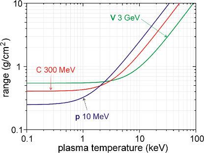
Ranges of different ion species with typical energies for IFI are shown in Fig. 2 as a function of the DT plasma temperature (). We have used the standard stopping power formula for classical plasmas, Eq.(2) Trubnikov ; Honrubia1993b . This formula predicts range lengthening when plasma electron velocities are comparable or higher than the fast ion velocity. Range lengthening is important for protons with maxwellian energy distributions generated away from the DT because it balances the reduction of the ion kinetic energy on target due to time spread, keeping the ion range almost constant during the ion pulse Temporal2002 . It is worth noting that the range lengthening in the temperature range 0.1 10 keV is substantially lower for ions heavier than protons, as shown in Fig. 2. This may be an issue for quasi-mononenergetic ions, as was pointed out in previous work Honrubia2014 ; Honrubia2009 .
The energy deposition of a perfectly collimated 10 MeV proton beam in DT computed by our FP model and by the standard ion tracking scheme are compared in Fig. 3. In both schemes, the energy deposited per unit pathlength decreases with the ion penetration because the electron stopping power is dominant and scales, roughly, as for 10 keV. The FP energy deposition profiles show beam scattering, straggling and blooming near the end of the range, the absence of the Bragg’s peak and a slight range shortening due to the proton scattering with the background ions. In the case of ion tracking, the energy deposition peaks at the end of the range, showing the well known Bragg’s peak, which may lead to underestimated ignition energies. Note that the Bragg’s peak disappears in the FP energy deposition profile due to proton scattering. For temperatures lower than 10 keV, scattering is less important and the differences between the FP and tracking energy deposition profiles are lower, but still significant.
To assess the importance of the FP energy deposition in FI targets, we have compared the ignition energies of the DT isochoric sphere initially at 400 gcm-3 and 100 eV heated by a uniform cylindrical beam. Atzeni et al. Atzeni2002 reported for this target a minimum ignition energy of 8.5 kJ. Our calculations show the same ignition energy when the ion scattering is off, while it increases slightly to 8.75 kJ for the FP energy deposition model. Thus, despite ion scattering effects seem not to be important for ion energy deposition, they are not negligible and should be taken into account in IFI calculations. Heavier ions, such as carbon, are less sensitive to scattering, being the ignition energies almost the same with and without scattering.
II.2 Ion pulse on target
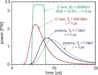
Beam power on target for proton and carbon ions with maxwellian energy distributions are plotted in Fig. 4. The beam temperatures are = 7 MeV and = 200 MeV, respectively. The pulse of quasi-monoenergetic carbon ions with a mean energy = 650 MeV and an energy spread of = 0.125 Fernandez2014 is also shown for comparison. All beams have an energy of 10 kJ and are generated at a distance to the simulation box = 500 m. The power on target of an ion beam generated instantaneously in a foil placed at a distance is given by the formula Temporal2002 :
| (9) |
where , and are the beam ion mass and temperature, respectively, the beam energy and the distance between the ion-generation foil and the simulation box. From Eq.(9), the beam power on target can be obtained for a pulse of duration . Assuming that ions are generated at the source foil at a constant rate over the pulse duration , the power on target is given by
| (10) |
with and . This formula has been used to calculate the pulses shown in Fig. 4. We assume an ion pulse duration of 1 ps throughout this paper, with exception of the quasi-monoenergetic beams, for which longer pulses, e.g. 3 ps in Fig. 4, are assumed to avoid very high peak powers. The feasibility of ps pulses for quasi-monoenergetic ion schemes such as BOA (break-out after burner) or RPA (radiation pressure acceleration) remains to be demonstrated Fernandez2014 .
II.3 Beam focusing
In addition to the ’conventional’ techniques of ion beam focusing such as ballistic transport Patel ; Key , magnetic lenses Schollmeier ; Harres ; Hofmann , and self-generated fields in hollow microcylinders illuminated by intense sub-picosecond laser pulses Toncian , laser-driven proton beam focusing has been demonstrated experimentally over the last years. Kar et al. Kar showed beam focusing by using rectangular or cylindrical hollow lens attached to a foil target. Offermann et al. Offermann found theoretically and experimentally that ion divergence depends on the thermal expansion of the co-moving hot electrons, resulting in a hyperbolic ion beam envelope. Using these results, Bartal et al. demonstrated experimentally an enhanced focusing of TNSA protons in cone targets, predicting spot diameters about 20 m for IFI conditions Bartal2012 , well under the 40 m spots required Honrubia2014 . The focusing mechanism reported by Bartal et al. is based on the onset of an electron sheath near the cone walls. This sheath generates focusing electrostatic fields that avoids the expansion of co-moving electrons. As these fields are generated near the cone walls, they affect mainly to the low energy ions, keeping the initial divergence of the higher energy ions generated closer to the beam axis. As a result, even in the case of a very good focusing by the cone walls, the beam will follow a hyperbolic path when traveling towards the core Bartal2012 ; Foord2012 ; Qiao2013 . Qiao and coworkers have pointed out by implicit PIC simulations that the setting up of the electron sheath at the cone walls may reduce substantially the laser-to-proton conversion efficiency for the long pulses required in IFI Qiao2013 . This can be mitigated by special designs of cone walls including insulator materials in order to reduce the electron flow between target and cone.
Recent experiments carried out at laser intensities of Wcm-2 relevant for IFI have evidenced the generation of highly collimated proton beams, i.e. with divergence full-angles lower than 10∘, in planar foils illuminated by high-contrast () laser beams Green2014 . This result together with those reported in Refs. Bartal2012 ; Qiao2013 , shows a clear path to achieve the focusing requirements of IFI if uniform and high contrast laser beams impinging on a curved target placed inside a cone are used to ignite the fuel.
As a precise determination of the beam path requires detailed PIC calculations, we have assumed that ions are focused to the cone apex or beyond and diverge from there to the compressed core with a given angle, which is taken as a parameter. The reference case calculations shown in the next Section assume that the ion beam is focused into a 30 m spot diameter at the inner surface of the cone tip. From this spot, the ion beam diverges with an opening half-angle as a parameter ranging from 0 to 20∘. For a given , each ion is injected in the simulation box with a randomly selected initial angle between and . This is an approximation of the curved ion beam trajectories found theoretically and experimentally Offermann , but allows us to assess the divergence effects on beam energy requirements. As the assumption of beam focusing at the inner surface of the cone tip may appear to be quite restrictive, we have considered also the cases of ions focused on the outer surface of the cone tip and on the coronal plasma near the dense DT core. In these two cases, the divergence effects are much lower than in the reference case due to the shorter stand-off distance between the focusing point and the core.
III Results
III.1 Optimal ion temperature
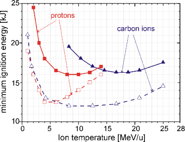
We start by determining the ion temperatures that maximize the beam-target coupling efficiency or, equivalently, minimize the beam energies required to ignite the target shown in Fig. 1. The results are depicted in Fig. 5 for proton and carbon ions with maxwellian energy distributions. We assume that TNSA carbon ions are generated by using thin, micrometer scale DLC foils with the rear surface free of protons. The ignition energies have been obtained as the minimum ion beam energy for which the thermonuclear fusion power has an exponential or higher growth sustained in time.
The shape of the curves shown in Fig. 5 can be explained as follows. For low temperatures, ions do not penetrate enough in the target to deposit a significant fraction of their energy into the dense core, raising the ignition energies. For high temperatures, ions penetrate into the core more than the optimal areal density of 1.2 gcm-2 Atzeni2002 raising again the ignition energies due to the increase of the DT mass heated by the beam.
Ignition energies depend on the target density distribution and, in particular, on the coronal plasma surrounding the core. For the 1D imploded density profile with the long coronal plasma shown in Fig. 1b, the ignition energies are minimized for the ’optimal’ ion temperatures of = 8 MeV and = 200 MeV for proton and carbon ion beams, respectively. For the super-gaussian density profile almost without coronal plasma shown in Fig. 1b, the optimal ion temperatures are = 6 MeV and = 150 MeV, respectively, substantially lower than those found for the imploded target density profile. Note also that even for the optimal ion temperatures, the ignition energies are, roughly, 30% higher for the imploded target due to the energy deposition in the coronal plasma. Even in this case, assuming a laser-to-ion conversion efficiency of 15% similar to that obtained recently in proton acceleration experiments Brenner2014 and close to the 12% found by Snavely et al. Snavely2000 , the laser beam energy requirements are around 100 kJ.
Independently of the DT density distribution, it is remarkable that the minimum ignition energies are similar for proton and heavier ions such as carbon, in agreement with our results for quasi-monoenergetic beams reported recently Honrubia2014 . On the contrary, the optimal ignition energies increase with the ion atomic number Z scaling, approximately, as (obtained for proton, carbon and other ion beams not shown), which is weaker than the dependence found for quasi-monoenergetc ions Honrubia2014 .
In order to simplify the analysis of the next sections, we assume = 7 MeV and = 200 MeV as ’optimal’ temperatures for the two density profiles depicted in Fig. 1b. Note that these ’optimal’ temperatures are in the plateau region where the ignition energies depend only weakly on the ion temperature for both density distributions, as shown in Fig. 5.
III.2 Optimal beam radius
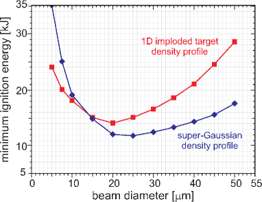
In order to determine the ion beam focusing requirements, we have studied the dependence of the ignition energies on the beam diameter. A perfectly focused proton beam with the ’optimal’ temperature = 7 MeV impinging on the target sketched in Fig. 1 has been chosen as model problem. The results are shown in Fig. 6. For beams with small diameter ( 10 - 15 m, depending on the density distribution), the energy density deposited is very high, heating the DT fuel up to high temperatures with the subsequent range lengthening of the beam ions. This, together with the strong hydrodynamic response of the DT plasma to the high energy deposition may result in ions passing through the dense core and even escaping by the target rear surface. As a result, the ignition energies rise up to high values.
For beams with diameter greater than 35 - 40 m, depending on the density distribution, the ignition energies rise again due to the increase of the DT volume heated by the beam. In this case, the ignition energies are sensitive to the ion energy losses in the coronal plasma, resulting in a substantial difference between the imploded and super-gaussian fuel density profiles, as shown in Fig. 6. Thus, for the simulation conditions analyzed here, beam diameters on DT core should be in the range between 15 and 35 m in order to get ignition energies close to the minimum value. This range defines the focusing requirements for IFI and is quite similar to that obtained in previous works for quasi-monoenergetic ions Honrubia2014 . We have assumed a beam diameter of 30 m in the analysis carried out in the next sections.
III.3 Energy deposition
As it was mentioned in the introduction, ions have the advantage of their classical interaction via Coulomb scattering with the background plasma. Unlike EFI, collective interactions due to self-generated fields do not play a significant role in IFI. This can be explained by the lower current densities found in IFI, which are about two orders of magnitude lower than in EFI for the same particle density. In addition, for ignition-scale targets, temperatures at the cone tip are high enough to mitigate strongly the growth of resistive fields. Hence, collective effects such as anomalous ion energy deposition, beam self-focusing and filamentation of co-moving electrons may not be important in IFI. Nevertheless, detailed investigations about those effects in IFI conditions are still open. A first step in this direction has been given by Qiao et al. Qiao2014 .
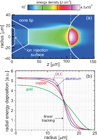
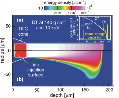
In addition to the initial ion beam divergence at the ion-generation foil, ions are scattered when passing through the cone tip, increasing its divergence Shmatov2011 . The effect of the cone tip material on the proton beam energy deposition is analyzed in Fig. 7, where the energy density deposited by the target of Fig. 1a heated by a proton beam with the ’optimal’ temperature = 7 MeV is shown. The increase of the beam diameter near the dense core seen in Fig. 7a evidences the proton scattering by the cone tip. As the mean deflection coefficient is proportional to the ion charge squared, Eq.(3), fast ion scattering is much lower for light materials, such as DLC or aluminum, as shown in Fig. 7b. On the contrary, for gold cones, scattering is important resulting in a substantial increase of the beam diameter near the dense core. For instance, in the case with a gold cone tip of Fig. 7a, the beam radius increases by around 8 m, which is of the same order than that obtained by Key et al. Key2006 by means of the Moliere’s multiple scattering theory (which provides the scattering angle in solid matter, being a lower limit in plasmas Shmatov2011 ). Moliere’s theory gives a 3.7∘ scattering angle for monoenergetic protons with energy = 10.5 MeV when traversing a 25 m solid gold foil. The corresponding increase of the beam radius at the DT core sited at a distance of 75 m from the outer surface of the cone tip is 4.8 m, which is almost a half of the 8 m shown in Fig. 7b. This can be explained by the maxwellian, not mononenergetic, energy distribution of protons and also by the more effective scattering by plasma ions than by solid matter. Enhancement of beam radii at the DT core results in higher ignition energies (see Fig. 6). For instance, the ignition energy of the target sketched in Fig. 1 is = 16.5kJ for DLC and aluminum cone tips, whereas it raises to 17.5 kJ and 21.5 kJ for copper and gold cones, respectively. Thus, we can conclude that the use of light materials at the cone tip is more suitable for IFI, similarly to EFI Johzaki2009 . A DLC cone tip is assumed in the reminder of this paper.
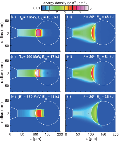
The energy deposition by proton and carbon ions with the optimal temperatures are compared in Fig. 8 for perfectly collimated and divergent beams. Energy deposition by quasi-monoenergetic carbon ions has been included also for comparison. We analyze first the perfectly collimated beams, Figs. 8a, c and e. Protons with a maxwellian energy distribution show a more localized energy deposition than carbon ions with the same distribution. This can be explained by the better balance between range lengthening (which is more pronounced for protons than for carbon ions) and energy spread found for proton beams. This effect is even more evident by comparing the energy deposition by maxwellian and quasi-monoenergetic carbon ions, which have a very small energy spread and, thus, their energy is deposited in a volume determined mainly by the range lengthening effect. The higher energy deposition by the maxwellian ions in the coronal plasma is also remarkable.
Note in Fig. 8 that the beams have a penetration into the dense core around 1.5 gcm-2, and slightly higher for the quasi-monoenergetic ions. These values are higher than the optimal value of 1.2 gcm-2 Atzeni1999 ; Atzeni2002 due to the energy deposition in the coronal plasma. The coupling efficiencies, defined as the energy deposited in the DT at densities higher than 200 gcm-3, for the perfectly collimated beams are 0.58 for the maxwellian proton and carbon beams, and 0.70 for the quasi-monoenergetic carbon ions, similar to those reported in Refs. Honrubia2009 ; Honrubia2014 . Coupling efficiencies rise substantially for the super-gaussian DT density distribution of Fig. 1b due to the lack of the coronal plasma, reaching the values of 0.86 for the maxwellian proton and carbon ions, and 0.87 for the quasi-monoenergetic carbon ions.
The energy deposition maps of beams with a divergence half-angle = 20∘ are shown in Figs. 8b, d and f. Note the large hot spot elongation due to the high beam divergence assumed, which distorts substantially the standard rectangular hot spot shape. As a result, the energy deposition volumes are higher than those found for collimated beams with the subsequent lower coupling efficiencies and higher ignition energies. For instance, the coupling efficiencies are 0.42 for maxwellian proton and carbon ions, increasing up to 0.59 for the quasi-monoenergetic carbon ions. Again, these ions penetrate deeper in the core, heating a much larger volume than the maxwellian ions.
III.4 Minimum ignition energies
The ignition energies for different beams as a function of the ion divergence half-angle are shown in Fig. 9. These energies have been obtained as described in Section III.A. As expected, the ignition energies show a rapid increase with the beam divergence angle. The small differences between maxwellian proton and carbon ions can be explained by the lower range lengthening of carbon ions, which does not balance completely their energy spread along the source-target distance. It is relevant here to recall that ignition energies are almost independent of the beam ion atomic number, provided that ions have the ’optimal’ mean kinetic energy, as can be seen in Fig. 5. The much lower ignition energies found for quasi-monoenergetic ions show the strong dependence of ignition energies on ion spectrum and the better coupling of quasi-monoenergetic ions with the plasma.
For maxwellian ions, the solid line curve labeled with solid squares corresponds to the ignition energies for the 1D imploded target density profile, while the dotted line curve labeled by empty squares corresponds to the super-gaussian density profile of Fig. 1b. Both curves show the limit cases of high and low coronal plasma areal density, respectively. Actually, the ignition energies of a realistic case would lie in between these curves, within the grey shaded area of Fig. 9. If we assume a laser-to-ion conversion efficiency of 15% Brenner2014 and an ignitor laser beam energy of 110 kJ, Fig. 9 shows that target ignition would be possible with maxwellian ions if the beam is perfectly collimated or has a divergence half-angle lower than 8∘ for high and low coronal plasma areal densities, respectively.
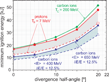
For quasi-monoenergetic ions, the ignition energies are substantially lower than those obtained for maxwellian ions. They are within the bottom shaded area of Fig. 9. Note that for the case of low areal density, the kinetic energy of carbon ions has been reduced from 650 to 400 MeV in order to have the optimal beam-target coupling.
For the divergence half-angles of 5∘ found in planar foils experiments Green2014 and assuming a laser-to-ion conversion efficiency of 15%, our results show that it would be sufficient with an igniting laser beam energy between 130 and 90 kJ for maxwellian ions, and from 75 to 60 kJ for quasi-monoenergetic ions, depending on the coronal plasma areal density.
III.5 Beam focusing beyond the cone tip
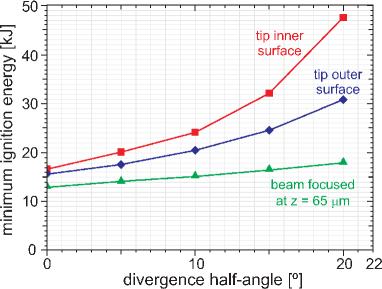
In the cases analyzed in Figs. 5 to 9, we have assumed that the beam is focused by the cone walls on the inner surface of the cone tip. In this case, the stand-off distance between the focusing point and the DT core is maximum and the beam has more room to spread out. As there is experimental and simulation evidence of beam focusing beyond the cone tip Qiao2013 ; Qiao2014 , it is worthwhile extending the study carried out in the last Sections to situations in which the beam is focused closer to the dense core. In this case, the DT heating by divergent beams is more efficient due to the lower beam radius at the core.
In order to analyze the effect of the beam focusing point on the ignition energies, two additional cases have been considered: (i) a proton beam focused on the outer surface of the cone tip and (ii) a proton beam focused 40 m away from the dense core ( = 65 m). In both cases, protons are focused on a 30 m diameter spot and have a maxwellian energy distribution with = 7 MeV. The ignition energies obtained for the 1D imploded target density profile are plotted in Fig. 10. Note the large reduction of the ignition energies when the proton beam is focused closer to the DT core. For instance, if the beam is focused 40 m away from the core, the ignition energies are much lower than in the reference case and depend weakly on the divergence half-angle. Even if the beam is focused on the outer rather than on the inner surface of the cone tip there is a substantial reduction of , specially for large divergence half-angles.
IV Conclusions
Our simulations have evidenced that ion beam ignition energies have been underestimated so far by using simplified energy deposition models and target designs. Fast ion spectrum, focusing spot diameter and position, beam divergence and ion scattering with the cone tip are key parameters that determine ignition energies. Taking into account all these parameters requires a kinetic treatment of ion energy deposition such as the linear Fokker-Planck model used in this work. Thus, our results generalize those obtained with the standard linear particle tracking method used so far.
Ignition energies of compressed targets have been evaluated in the limits of high and low coronal plasma areal densities. The goal has been to obtain an upper and lower limits of beam energy requirements for IFI. The results of our study can be summarized as follows:
i) The ion beam diameter on the dense core should not exceed around 40 m, which is even higher than the focal spots inferred from experiments Bartal2012 and obtained in large scale PIC simulations of ion acceleration in the IFI scenario Qiao2013 . Beam focusing is one of the most challenging issues of IFI, with high chances of success in future IFI experiments.
ii) The cone tip material should be as light as possible in order to reduce ion scattering. Intermediate materials such as copper are acceptable because they give rise to a modest increase of the ignition energies when compared with light materials.
iii) As expected, ignition energies depend strongly on the beam divergence. Our calculations show that for the beam divergence half-angle of 5∘ measured in the recent experiments, the ion beam ignition energies of the targets considered here are from 13 to 20 kJ, depending on the density distribution of the imploded fuel. These energies are substantially higher than the standard ignition energies of 10 kJ considered so far.
iv) Assuming the laser-to-proton conversion efficiency of 15% found in recent experiments Brenner2014 , the laser beam energies required for ignition are in between 90 and 130 kJ for small and large coronal plasma areal densities, respectively. In principle, these energies could be affordable with the present laser technology.
v) The position of the ion beam focusing point is crucial to reduce the ignition energies. If it is beyond the cone tip, the ignition energies would be reduced substantially and would be less sensitive to the ion divergence.
vi) If beam focusing were demonstrated for advanced schemes, such as the break-out afterburner scheme Fernandez2014 , quasi-monoenergetic ions instead of TNSA ions should be used due to their better coupling with the compressed fuel.
The challenge over the forthcoming years will be to perform experiments relevant for a full characterization of ion generation, focusing and interaction with imploded targets in conditions close to those found in IFI. The success of IFI will depend on the possibility of generating ions by means of high contrast, highly uniform laser beams and focusing the ion beam into 20 - 30 m spots as close as possible to the imploded DT core.
Future studies will include PIC simulations of ion acceleration and focusing to get a full characterization of the ion source. This will be followed by integrated simulations similar to those presented here, but with a self-consistent ion source.
Acknowledgements.
One of the authors (J.J.H.) would like to thank the fruitful discussions and the hospitality during his stay at ILE. This work used resources and technical assistance from the CeSViMa HPC Center of the Polytechnic University of Madrid.References
- (1) M. Tabak. J. Hammer, M.E. Glinsky, W.L. Kruer, S.C. Wilks, J. Woodworth, E.M. Campbell, M.D. Perry and R.J. Mason, Phys. Plasmas 1, 1626 (1994).
- (2) A.J. Kemp, F. Fiuza, A. Debayle, T. Johzaki, W.B. Mori, P.K. Patel, Y. Sentoku and L.O. Silva, Nucl. Fusion 54, 054002 (2014).
- (3) A.P.L. Robinson, D. Strozzi, J.R. Davies, L. Gremillet, J.J. Honrubia, T. Johzaki, R.J. Kingham, M. Sherlock and A.A. Solodov, Nucl. Fusion 54, 054003 (2014).
- (4) M. Tabak and D. Callahan-Miller, Nucl. Instr. Meth. 415, 75 (1998).
- (5) M. Roth, T.E. Cowan, M.H. Key, S.P. Hatchett, C. Brown, W. Fountain, J. Johnson, D.M. Pennington, R.A. Snavely, S.C. Wilks, K. Yasuike, H. Ruhl, F. Pegoraro, S.V. Bulanov, E.M. Campbell, M.D. Perry and H. Powell, Phys. Rev. Lett. 86, 436 (2001).
- (6) J.C. Fernández, B.J. Albright, F.N. Beg, M.E. Foord, B.M. Hegelich, J.J. Honrubia, M. Roth, R.B. Stephens and L. Yin, Nucl. Fus. 54, 054006 (2014).
- (7) S.M. Weng, M. Murakami, H. Azechi, J.M. Wang, N. Tasoko, M. Che, Z.M. Sheng, P. Mulser, W. Yu and B.F. Shen, Phys. Plasmas 21, 012705 (2014).
- (8) B.J. Albright, M.J. Schmitt, J.C. Fernández, G.E. Cragg, I. Tregillis, L. Yin and B.M. Hegelich, J. Phys.: Conf. Ser. 112, 022029 (2008).
- (9) J.J. Honrubia, J.C. Fernández, B.M. Hegelich, M. Murakami and C.D. Enriquez, Laser and Particle Beams 32, 419 (2014).
- (10) Dong-Xiao Liu, Wei Hong, Lian-Qiang Shan, Shun-Chao Wu and Yu-Qiu Gu, Plasma Phys. Control. Fusion 53, 035022 (2011).
- (11) M. Temporal, Phys. Plasmas 13, 122704 (2006).
- (12) M. Temporal, J.J. Honrubia and S. Atzeni, Phys. Plasmas 15, 052702 (2008).
- (13) C.M. Brenner, A.P.L. Robinson, K. Markey, R.H.H. Scott, R.J. Gray, M. Rosinski, O. Deppert, J. Badziak, D. Batani, J.R. Davies, S.M. Hassan, K.L. Lancaster, K. Li, I.O. Musgrave, P.A. Norreys, J. Pasley, M. Roth, H.-P. Schlenvoigt, C. Spindloe, M. Tatarakis, T. Winstone, J. Wolowski, D. Wyatt, P. McKenna and D. Neely, App. Phys. Lett. 104, 081123 (2014).
- (14) T. Bartal, M.E. Foord, C.Bellei, M.H. Key, K.A. Flippo, S.A. Gaillard, D.T. Offermann, P.K. Patel, L.C. Jarrott, D.P. Higginson, M. Roth, A. Otten, D. Kraus, R.B. Stephens, H.S. McLean, E.M. Giraldez, M.S. Wei, D.C. Gautier and F.N. Beg, Nat. Phys. 8, 139 (2012).
- (15) R.A. Snavely, M.H. Key, S.P. Hatchett, T.E. Cowan, M. Roth, T.W. Phillips, M.A. Stoyer, E.A. Henry, T.C. Sangster, M.S. Singh, S.C. Wilks, A. MacKinnon, A. Offenberger, D.M. Pennington, K. Yasuike, A.B. Langdon, B.F. Lasinski, J. Johnson, M.D. Perry, and E.M. Campbell, Phys. Rev. Lett. 85, 2495 (2000).
- (16) P. Mora, Phys. Rev. Lett. 90, 185002 (2003)
- (17) M. Murakami and M.M. Basko, Phys. Plasmas 13, 012105 (2006).
- (18) S.P. Hatchett et al., Cone-focused fast ignition: Sub-Ignition Proof-of-Principle Experiments, (Ed. M. Key) contribution to the 6th Workshop on Fast Ignition of Fusion Targets , 16-18 November2002, St. Petes Beach, Florida, USA (2002).
- (19) S. Atzeni, M. Temporal and J.J. Honrubia, Nucl. Fus. 42, L1 (2002).
- (20) M. Temporal, J.J. Honrubia and S. Atzeni, Phys. Plasmas 9, 3098 (2002).
- (21) R. Ramis and J. Ramírez, Indirectly driven target design for fast igniton with proton beams, Nucl. Fusion 44, 720 (2004).
- (22) J.C. Fernández, J.J. Honrubia, B.J. Albright, K.A. Flippo, D.C. Gautier, B.M. Hegelich, M.J. Schmitt, M. Temporal and L. Yin, Nucl. Fus. 49, 065004 (2009).
- (23) J.J. Honrubia, J.C. Fernández, M. Temporal, B.M. Hegelich and J. Meyer-ter-Vehn, Phys. Plasmas 16, 102701 (2009).
- (24) V.T. Tikhonchuk, T. Schlegel, C. Regan, M. Temporal, J.-L. Feugeas, Ph. Nicolaï and X. Ribeyre, Nucl. Fusion 50, 045003 (2010).
- (25) S.M. Weng, M. Murakami, P. Mulser and Z.M. Sheng, New J. Phys. 14, 063026 (2012).
- (26) M.E. Foord, T. Bartal, C. Bellei, M. Key, K. Flippo, R.B. Stephens, P. K. Patel, H. S. McLean, L.C. Jarrott, M.S. Wei and F.N. Beg, Phys. Plasmas 19, 056702 (2012).
- (27) M.H. Key, R.R. Freeman, S.P. Hatchett, A.J. MacKinnon, P.K. Patel, R.A. Snavely and R.B. Stephens, Fusion Sci. and Tecnol. 49, 440 (2006).
- (28) C.D. Clark and M. Tabak, Nucl. Fus. 47, 1147 (2007).
- (29) H.D. Shay, P. Amendt, D. Clark, D. Ho, M. Key, J. Koning, M. Marinak, D. Strozzi and M. Tabak, Phys. Plasmas 19, 092706 (2012).
- (30) J.J. Honrubia and J. Meyer-ter-Vehn, Plasma Phys. Control. Fusion 51, 014008 (2009).
- (31) T. Johzaki, Y. Nakao and K. Mima, Phys. Plasmas 16, 062706 (2009).
- (32) A.A. Solodov, K.S. Anderson, R. Betti, V. Gotcheva, J. Myatt, J.A. Deletrez, S. Skupsky, W. Theobald and J.C.Stoeckl, Phys. Plasmas 16, 056309 (2009).
- (33) D.J. Strozzi, M. Tabak, D.J. Larson, L. Divol, A.J. Kemp, C. Bellei, M.M. Marinak and M.H. Key, Phys. Plasmas 19, 072711 (2012).
- (34) J.J. Honrubia, J. Quant. Spectrosc. Radiat. Transfer 49, 491 (1993).
- (35) J.J. Honrubia, Charged particle transport in Fusion by Inertial Confinement, G. Velarde, Y. Ronen and J.M. Martínez-Val (Eds.), CRC Press, Boca Ratón, Florida (1993).
- (36) SESAME: The Los Alamos National Laboratory Equation of State Database, LA-UR-92-3407 (1992).
- (37) J.J. Honrubia, C. Alfonsín, L. Alonso, B. Pérez and J.A. Cerrada, Laser Part. Beams 24, 217 (2006).
- (38) B.A. Trubnikov, Particle interactions in a fully ionized plasma in Review of Plasma Physics, M.A. Leontovich (Ed.), Vol. 1, Consultants Bureau, New York (1965).
- (39) P.K. Patel, A.J. Mackinnon, M.H. Key, T.E. Cowan, M.E. Foord, M. Allen, D.F. Price, H. Ruhl, P.T. Springer and R. Stephens, Phys. Rev. Lett. 91, 125004 (2008).
- (40) M.H. Key, Phys. Plasmas 14, 055502 (2007).
- (41) M. Schollmeier, S. Becker, M. Geiel, K.A. Flippo, A. Blazevic, S.A. Gaillard, D.C. Gautier, F. Gruner, K. Harres, M. Kimmel, F. Nurnberg, P. Rambo, U. Schramm, J. Schreiber, J. Schutrumpf, J. Schwarz, N.A. Tahir, B. Atherton, D. Habs, B.M. Hegelich, and M. Roth, Phys. Rev. Lett. 101, 055004 (2008).
- (42) K. Harres, I. Alber, A. Tauschwitz, V. Bagnoud, H. Daido, M. Günther, F. Nürnberg, A. Otten, M. Schollmeier, J. Schütrumpf, M. Tampo and M. Roth, Phys. Plasmas 17, 023107 (2010).
- (43) I. Hofmann, J. Meyer-ter-Vehn, X. Yan, A. Orzhekhovskaya and S. Yaramyshev, Phys. Rev. ST Accel. Beams 14, 031304 (2011).
- (44) T. Toncian, M. Borghesi, J. Fuchs, E. d’Humières, P. Antici, P. Audebert, E. Brambrink, C.A. Cecchetti, A. Pipahl, L. Romagnani and O. Willi, Science 312, 410 (2006).
- (45) S. Kar, K. Markey, P.T. Simpson, C. Bellei, J.S. Green, S.R. Nagel, S. Kneip, D.C. Carroll, B. Dromey, L. Willingale, E.L. Clark, P. McKenna, Z. Najmudin, K. Krushelnick, P. Norreys, R.J. Clarke, D. Neely, M. Borghesi, and M. Zepf, Phys. Rev. Lett. 100, 105004 (2008).
- (46) D.T. Offermann, K.A. Flippo, J. Cobble, M.J. Schmitt, S.A. Gaillard, T. Bartal, D.V. Rose, D.R. Welch, M. Geissel and M. Schollmeier, Phys. Plasmas 18, 056713 (2011).
- (47) B. Qiao, M.E. Foord, M.S. Wei, R.B. Stephens, M.H. Key, H. McLean, P.K. Patel and F.N. Beg, Phys. Rev E 87, 013108 (2013).
- (48) J.S. Green, N.P. Dover, M. Borghesi, C.M. Brenner, F.H. Cameron, D.C. Carroll, P.S. Foster, P. Gallegos, G. Gregori and P. McKenna, Plasma Phys. Control. Fus. 56, 084001 (2014).
- (49) B. Qiao et al., Acceleration, Focusing and Energy Deposition of High Intensity Proton Beams in the kilojoule multi-picosecond Laser Regime for Fast Ignition, presented at the 2nd International Conference on High Energy Density Physics, Beijing, China, September 21 - 24 (2014).
- (50) M.L. Shmatov, Laser Part. Beams 29, pp. 339-344 (2011).
- (51) S. Atzeni, Phys. Plasmas 6, 3316 (1999).