Opportunistic Interference Alignment for Random Access Networks
Abstract
An interference management problem among multiple overlapped random access networks (RANs) is investigated, each of which operates with slotted ALOHA protocol. Assuming that access points and users have multiple antennas, a novel opportunistic interference alignment (OIA) is proposed to mitigate interference among overlapped RANs. The proposed technique intelligently combines the transmit beamforming technique at the physical layer and the opportunistic packet transmission at the medium access control layer. The transmit beamforming is based on interference alignment and the opportunistic packet transmission is based on the generating interference of users to other RANs, which can be regarded as a joint optimization of the physical layer and the medium access control layer. It is shown that the proposed OIA protocol significantly outperforms the conventional schemes such as multi-packet reception and interference nulling.
Index Terms:
Interference alignment, interference nulling, multi-packet reception, random access networks, slotted ALOHA, transmit beamforming.I Introduction
Recently, interference management in random access networks has attracted a great interest. For an example, the working group of IEEE 802.11, which is one of the most successful standards in commercial wireless communication systems, is considering performance improvement for overlapping basic service sets (OBSS) under the new standardization called IEEE 802.11 high efficiency wireless local area network (HEW) [1]. It is known that OBSS experiences severe interference and the interference among OBSS is a primary problem that IEEE 802.11 HEW should overcome.
On the other hand, interference alignment (IA) [2] has been considered as a promising solution to achieve the optimal degrees-of-freedom (DoF) in several interference network models including cellular networks. Suh and Tse characterized the DoF of the -cell uplink cellular network and they proposed an achievable scheme for the optimal DoF [3]. The main idea of [3] is to align the interferences from users in other-cells to predefined interference spaces, and it was shown that the achievable DoF increases as the number of users transmitting concurrently increases. To apply IA, global channel state information (CSI) is required and, hence, some performance degradation may occur as long as there happens CSI feedback quantization in practice. The related performance was analyzed in [4] along with a further performance optimization. In addition, opportunistic IA (OIA) has been proposed for the -cell uplink network in which user scheduling is combined with IA. Unlike the original IA technique, OIA does not require global CSI, time/frequency expansion, and iterations for beamformer design, thereby resulting in easier implementation [5, 6]. Later, [7] compared OIA to the traditional IA with quantized CSI and indicated the advance of OIA. To further improve the performance of OIA, an active alignment transmit beamforming scheme was proposed in [8] which perfectly aligns the interference to the reference interference direction of one BS and, therefore, achieves partial IA with nonzero probability. As the previous OIA schemes mostly minimize the inter-cell interference, a new OIA scheme that additionally considers the intra-cell power loss was also proposed in [9].
IA techniques have been also applied to random access networks (RANs) based on carrier sensing multiple access (CSMA) mechanisms [10, 11]. In [10], multiple packets from users in other overlapped networks are aligned at the physical (PHY) layer and the decoded packets are assumed to be exchanged through wired backhaul such as Ethernet. Basically, at the medium access control (MAC) layer in [10], users are scheduled like the point coordinated function (PCF) which is a part of IEEE 802.11 standard. Thus, the proposed IA algorithm in [10] requires tight coordination among access points (APs) in overlapped networks through wired backhaul and it does not consider collisions among users even though the collision effect is the most important factor to degrade the performance of RANs. IA was applied to a fully distributed random access environment in [11] like the distributed coordinated function (DCF) of IEEE 802.11 standard. In [11], the proposed MAC protocol allows a new transmission even when there exist ongoing transmissions already in overlapped networks as long as the new transmitter and receiver have a sufficiently large number of antennas and ensure no interference to ongoing transmissions. Thus, if users have the same number of antennas, then the performance improvement becomes limited. Moreover, the DoF of multiple access channel was characterized when both users and AP have multiple antennas and each user independently decides whether to transmit in a specific time, which can be regarded as the uplink scenario of a single RAN [12]. In [12], the authors proved the optimal average DoF can be achieved by the interference alignment in specific network scenarios, but the interference among multiple RANs is not considered.
In this paper, we propose a novel OIA protocol in order to efficiently manage the interference among overlapped RANs operating in slotted ALOHA protocol. The proposed OIA protocol jointly considers PHY and MAC layers. In the PHY layer, a beamforming algorithm based on singular value decomposition (SVD) is adopted to minimize generating interference from each user to other overlapped RANs. In the MAC layer, a novel opportunistic random access algorithm is proposed, which is based on cumulative distribution function (CDF) of each user’s generating interference. Therefore, the proposed OIA protocol is a cross-layer solution for interference-limited RANs.
The main differences between the proposed OIA protocol and the conventional OIA algorithm [5, 6] are as follows.
-
•
Each user determines to send packets for itself in the proposed OIA protocol, while base stations determine which users send packets in the conventional OIA algorithm.
-
•
The proposed OIA protocol utilizes the CDF value of each user’s generating interference as random access criterion, while the conventional OIA algorithm utilizes the very generating interference as a scheduling criterion.
-
•
The number of concurrently transmitting users in the network is a random variable in the proposed OIA protocol, while it is fixed in the conventional OIA algorithm. Thus, the proposed OIA protocol examines the number of concurrently transmitting users in the network and changes the packet decoding methodology according to the number of concurrently transmitting users.
The rest of this paper is organized as follows: Section II describes the system model and Section III introduces the conventional techniques which can be used for interference-limited RANs. In Section IV, the OIA protocol for the interference-limited RANs is proposed. Section V evaluates the throughput performance of the proposed OIA protocol and, finally, Section VI concludes the paper.
II System model
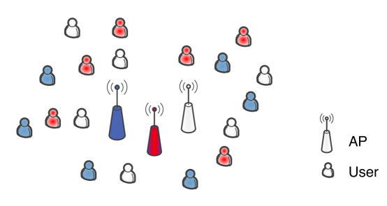
We consider an uplink scenario in overlapped RANs each of which has one AP and users. Each AP and each user are assumed to have and antennas, respectively. Fig. 1 shows an example network where three RANs are overlapped. We assume that each RAN operates with slotted ALOHA and transmission time is equally divided by slots. At each slot, each user transmits a packet to its serving AP with probability . Due to the nature of random access, simultaneous transmissions from multiple users is inevitable. Assuming that RANs are geometrically overlapped, such concurrent packet transmissions from multiple users in different RANs cause interference due to the broadcasting property of wireless medium. The channel matrix from the -th user in the -th RAN to the -th AP is denoted by , where and . The received signal at the -th AP, , is given as
| (1) |
where denotes the random variable representing the activity of the -th user in the -th RAN and . Hence, becomes zero if the user has no packet to transmit. and denote the information stream and its transmit beamforming vector of the -th user in the -th RAN, respectively. Let and . That is, indicates the number of concurrently transmitting users in the -th RAN and indicates the total number of concurrently transmitting users in all RANs. We assume that each user experiences Rayleigh fading and the channel gain independently changes in each time slot. Each AP is assumed to periodically transmit a pilot signal so that the users can estimate their channels to all APs located in the overlapped area by using the reciprocity of the wireless channel. In this paper, we also assume that each user transmits a single information stream. represents the additive Gaussian noise at the -th AP. Furthermore, the -th user in the -th RAN is assumed to know its outgoing channels , , by exploiting the channel reciprocity, i.e., the local CSI at the transmitter. In addition, we assume the interference-limited networks and the average path-loss from users to APs are assumed to be identical to each other for simplicity.
III Conventional Techniques for Interference-Limited RANs
III-A Multi-Packet Reception (MPR)
For designing RANs, the mitigation of collision effects among simultaneously transmitting users is one of the most challenging issues. It has been shown that multi-packet reception (MPR) at the PHY layer, which is implemented through multi-user multiple-input multiple-output (MIMO) techniques in general, can be a promising solution [13]. As assumed in Section II, each user transmits a single stream and each AP has antennas, each AP can successfully decode up to packets from transmitting users in the overlapped area by using the MPR technique [14]. In practice, the probability that each AP successfully decodes the received packets depends on the number of concurrently transmitting users. The average throughput (packets/slot) in the MAC layer of -overlapped RANs with the MPR technique is obtained as
| (2) |
where denotes the total number of users in the -overlapped RANs and denotes the probability that each received packet is successfully decoded when there exist concurrently transmitting users in the whole -overlapped RANs. Note that if the -th RAN has users’ simultaneous transmissions, . Although the -th AP may try to decode all the users’ packets, only the packets are useful for it and it may throw the other decoded packets. Obviously, decreases as increases due to the interferences from users. More detailed analysis on is given in [13, 14].
III-B Interference Nulling (IN)
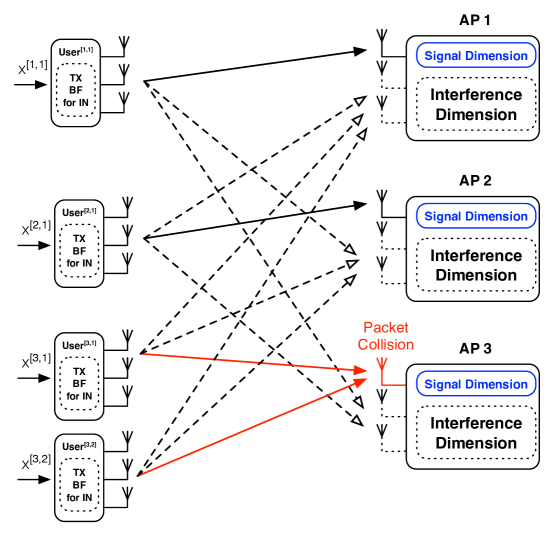
In addition to MPR, we can also consider the interference nulling (IN) technique which utilizes the transmit beamforming at each user for overlapped RANs. For applying the IN technique, each AP sets spatial dimensions for receiving signals from its serving users. Then, each user performs transmit beamforming to make its signal arriving at the signal spaces of the other APs be zero. Assuming overlapped RANs and dimensional signal space at each AP, each user should make its transmit signal, which is arrived at dimensional signal space in other APs, be zero. Hence, the dimension of signal space at each AP, , should satisfy the following constraint:
| (3) |
where indicates the number of transmit antennas at users. Fig. 2 shows a transmission scenario with the IN technique when , , and , which satisfies the condition in (3). In this figure, it is assumed that , , and . In Fig. 2, without loss of generality, each AP is assumed to set its first antenna as the signal space for receiving packets from its serving users, while other two antennas are reserved for interference signals from other RANs. All transmitting users in the overlapped networks perform transmit beamforming in order to null out the interference at other APs’ signal spaces, which is the first antenna of each AP in Fig 2. Each AP receives the signals from the users belong to itself through the first antenna, and each AP operates as an independent cell since there is no interference from other cells for the first antenna. In Fig. 2, there is a packet collision in the third RAN, but the APs in the first and second RANs can receive a packet successfully since interference signals are still nulled out at the signal spaces.
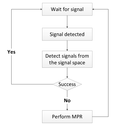
If the number of concurrently transmitting users in a specific RAN is less than or equal to , that is, , , then each AP can surely decode the received signals with the MPR technique regardless of the number of transmitting users in other RANs. However, if the number of concurrently transmitting users in a specific RAN is larger than but the number of concurrently transmitting users in all the RANs is smaller than , that is, but , , then the AP can still successfully decode the received signal by using all receive antennas with MPR. The overall signal detection procedure of the IN technique is shown in Fig. 3.
By taking into account this possibility, the throughput at the MAC layer with the IN technique is given as
| (4) |
where denotes the probability that the received signals are successfully decoded when and users concurrently transmit packets in a specific RAN and the other RANs respectively and each AP sets antennas as the signal space. Here, is assumed to satisfy the condition in (3). In (4), the first summation in the brace shows the throughput of each RAN obtained from the signals arriving at the -dimensional signal space. The second summation shows the throughput obtained when the number of simultaneously transmitting users in a RAN is larger than but the total number of simultaneously transmitting users in the whole RANs, , is less than . Note that the AP may possibly decode those packets by performing MPR with its whole antennas if the concurrently transmitting users in the RANs are no larger than . In (4), is the probability that users are simultaneously transmitting in a RAN and the formula in the bracket shows the probability that the number of simultaneously transmitting users in other RANs is no larger than . As we consider the total throughput of the -overlapping RANs, the factor of is appeared outside of the brace in (4).
IV Opportunistic Interference Alignment
As mentioned before, the constraint on the dimension of signal space, which is shown in (3), limits the DoF in each RAN and restricts the applicability of the IN technique in practice. In this section, we propose the OIA protocol which efficiently controls the interference among overlapped RANs. In the proposed OIA protocol, the DoF in each RAN, , is not limited by (3) and can be arbitrarily set from to . The OIA protocol is designed by considering both the PHY and MAC layers, which is as follows.
IV-A PHY Layer: SVD-Based Transmit Beamforming
First of all, the -th AP sets its interference space for interference alignment, which is denoted by , where is the orthonormal basis, and . Here, denotes the dimension of the signal space reserved at each AP and it is assumed that for all for convenience in this subsection since we focus on the operation at the PHY layer. Obviously, can vary from to according to the MAC layer operation which is the focus of the next subsection. For given , the -th AP also calculates the null space of , defined by
| (5) |
where is the orthonormal basis, and broadcasts it to all users in the network.111By using the pre-defined pseudo-random pattern, can be informed to users without any signaling process and each user may compute in a distributed manner without being informed. If , then can be any orthonormal matrix.
We assume the unit-norm beamforming vector at the -th user in the -th RAN as , i.e., . From and , the -th user in the -th RAN calculates its effective generating interference, called leakage of interference (LIF), from
| (6) |
where , , and . Here, denotes the projection operation of onto the null space of and denotes the Hermitian operation. LIF can be regarded as the interference power which is received at the -th AP and not aligned at the interference space .
Instead of perfectly nulling interference from users to other RANs, the proposed transmit beamforming is performed to minimize sum of the effective interference power to other APs. Thus, each user finds the optimal transmit beamforming vector that minimizes its LIF metric which defined as:
| (7) |
where is defined by
| (8) |
Let us denote the SVD of as
| (9) |
where and consist of orthonormal columns, respectively, and , where . Then, it is apparent that the optimal is determined as
| (10) |
where is the -th column of . With this choice, is achievable.
After receiving signals at the -th AP, is multiplied to remove the interference that is aligned to the interference space of the AP, . Then, the received signal can be expressed as:
| (11) |
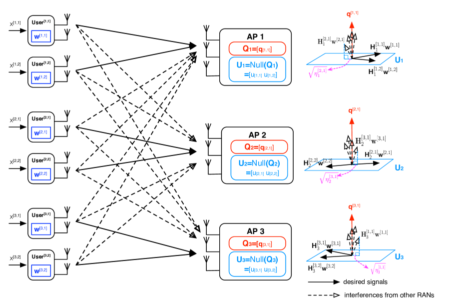
When , this beamforming makes the interference signals be zero. Thus, the proposed OIA includes the IN technique presented in Section III-B. On the other hand, when , the users’ transmissions may cause interference to the packet received at other APs. Fig. 4 shows the geometric signal structure of the proposed OIA protocol at APs when , , and , which corresponds to the case where and, as a result, the IN technique cannot be applied. For simplicity, we assume that the interference space of each AP is the same in Fig. 4. Note that the proposed transmit beamforming minimizes the LIF metric in (7). In the next subsection, we will introduce an opportunistic random access mechanism to further reduce such interference.
IV-B MAC Layer: Interference-Aware Opportunistic Transmission
Although the SVD-based transmit beamforming minimizes the interference to other RANs at the PHY layer, the residual interference may exist in the signal space at APs. Hence, we need further reduce the interference at the MAC layer by exploiting opportunistic random access. In the conventional OIA technique proposed for cellular networks, the number of transmitting users in each cell is fixed according to the predetermined scheduling policy. In RANs, however, the number of concurrently transmitting users in each RAN is a random variable which can vary over time by nature. While the conventional opportunistic random access in RANs maximizes the signal strength of users [15], each user applies the opportunism based on its effective generating interference to other RANs, i.e., the LIF metric in (7), in the proposed OIA protocol.
Each user observes its LIF metric for a long time to obtain the corresponding cumulative distribution function (CDF). Specifically, in each time slot, each user calculates its instant LIF metric based on (7) and stores it to update the histogram of the LIF values from which the CDF can be calculated by normalization. Another possible methodology to obtain the CDF is as follows: Let be the stored CDF at slot and the LIF calculated at slot be . Then the CDF can be updated as
| (12) |
where is the observation window. With larger and , we can obtain a more accurate CDF.
Once the CDF is determined, each user finds the output of the obtained CDF by using the instant LIF metric. In the proposed OIA protocol, each user transmits a packet if the output of the CDF is smaller than a certain threshold. Note that the CDF values are uniformly distributed in [16]. The transmission probability of each user becomes by setting the threshold to . If a user already has a steady state CDF of , the equivalent operation of the proposed protocol is that the user transmits its packet if the current LIF metric is smaller than . As long as the number of simultaneously transmitting users in a RAN is smaller than , the AP may decode the desired streams by treating the signals from other cells as interference which is minimized by the opportunistic transmission at the MAC layer and the SVD-based beamforming at the PHY layer.
As the number of users in each RAN, , increases, the transmission probability, , should be decreased in order to avoid packet collisions among users. Then, the decrease of also leads to the decrease of the generating interference of each user to other RANs. Hence, we can conclude that the interference among RANs would be reduced as increases since a smaller makes the LIF become smaller.
In the proposed OIA protocol, each user needs to calculate its instant LIF value and find the corresponding CDF value in each time slot. This process may result in computational burden to users since channel estimation and SVD operation are required. However, most interference management techniques, including the conventional OIA algorithms proposed for cellular uplink/downlink networks, require users to estimate the interference channels to other cells for exploiting opportunistic user scheduling. In addition, obtaining CDF value does not yield severe computational burden at each user, compare to the channel estimation operation. Thus, the proposed OIA protocol has a similar computational complexity with the conventional OIA algorithms. Note that the proposed OIA does not require users to feed back channel matrix or scheduling metric, i.e., CDF value, to their APs, while the conventional OIA algorithms in cellular networks require all users to feed back their LIF and beamforming vector to the corresponding base stations. Therefore, the proposed OIA protocol does not increase computational complexity much at each user, and it can be applied to practical RANs (such as wireless LANs) without significant modifications.
IV-C Throughput Analysis
If the number of concurrently transmitting users in each RAN is smaller than , , and the residual interference at APs is small enough, then the throughput of the OIA protocol can be expressed as a similar form in (4). Note that the constraint shown in (3) does not limit in the proposed OIA protocol. In practice, however, the residual interference at the APs may reduce the packet success probability. The packet success probability of the -th AP may depend on the dimension of reserved signal space (), the number of concurrently transmitting users in the -th RAN (), the number of receive antennas at AP (), the number of transmit antennas at each user (), and the number of concurrently transmitting users in other RANs (). Hence, the throughput of the proposed OIA protocol can be expressed as:
| (13) |
where denotes the probability that the received packets are successfully decoded, when there exist concurrently transmitting users in a specific RAN and concurrently transmitting users exist in other RANs for given , , and . If the total concurrently transmitting users in whole networks () is less than the number of receive antennas at APs (), then the MPR technique can be used for decoding the received packets. This phenomenon results in the throughput of a single RAN shown by the first summation in the brace of (13). On the other hand, if and , then the probability that the received packets are successfully decoded is determined by the proposed OIA protocol which includes the transmit beamforming, opportunistic access, and receive beamforming. The corresponding throughput is described by the second summation in the brace of (13). Note that here only the scenarios where are reflected to exclude the cases already considered in the first summation. Unfortunately, is not mathematically tractable due to complicated interactions among many factors such as the time-varying nature of the number of active users in RANs, and it should be evaluated by simulations. In Section V, we evaluate by simulation and demonstrate the resultant throughput of the proposed OIA protocol in various environments.
V Numerical Results
We first consider a three-overlapped network each of which supports users ( and ). Both APs and users have three antennas () and the channel matrix between each transmit–receive antenna pair is assumed to experience Rayleigh fading. The average received signal-to-noise ratios (SNRs) at APs from all users in the network are assumed to be dB. The APs adopt zero-forcing (ZF) technique for decoding the multiple received signals in all protocols including MPR, IN, and the proposed OIA. In particular, in the proposed OIA protocol, the ZF decoder is used for decoding packets from users in the corresponding RAN after null projection as shown in (11). The signal-to-interference-plus-noise ratio (SINR) threshold for successful packet decoding is assumed to be dB.222This value can be varied according to PHY layer data-rate at transmitters, but we use a single threshold in this paper since we focus on the MAC layer throughput. Furthermore, we found that the performance tendencies in this section are not changed according to various threshold through extensive simulations.
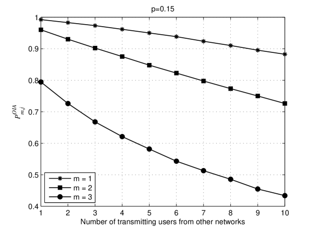
We first consider the PHY layer performance of OIA for the first RAN as a representative example. Fig. 5 shows the PHY-layer packet success probability of OIA, , by varying the number of simultaneously transmitting (or active) users from other RANs when and . Three cases are considered where the numbers of concurrently transmitting users in the first RAN are 1, 2, and 3. To investigate the steady state performance, the CDF of LIF is obtained by collecting samples. We can observe that decreases with a larger or . At the MAC layer, the number of concurrently transmitting users, and , vary slot by slot due to the random access nature of the -persistent protocol. Specifically, the first network sees local users’ simultaneous transmissions with probability and more users’ simultaneous transmissions from the other RANs with probability , respectively. This phenomenon was implemented in the simulations performed in this paper. If and , a collision (or transmission fail) happens. If , a smaller happens with a larger or as shown in Fig. 5. A larger indicates a reduced DoF for the decoding at the users in the first RAN while a larger indicates a larger interference from the other RANs.
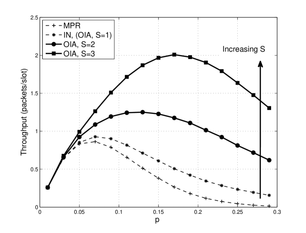
Fig. 6 compares the throughput of the proposed OIA protocol with the conventional techniques including the MPR and IN techniques for varying the transmission probability, . The proposed OIA protocol achieves much better throughput than the MPR and IN techniques. Note that the IN technique in the figure is identical to the proposed OIA protocol with because the condition (3) is satisfied in this case and the OIA protocol operates in the same way as the IN technique, as discussed in Section IV. The IN technique achieves better throughput than the MPR technique regardless of the transmission probability. The throughput increases as the dimension of signal space in the OIA protocol () increases, and thus we can conclude that a larger value of is preferable for the proposed OIA protocol in this network scenario. For each scheme, there exists the optimal transmission probability that maximizes the throughput. We can observe that the optimal transmission probability of the proposed OIA protocol increases as increases, which implies that more aggressive transmission is preferable for larger . For example, the maximum throughput of the OIA protocol with is equal to packets/slot, while that of the MPR technique is equal to packets/slot. Hence, the OIA protocol yields throughput improvement, compared to the MPR technique.
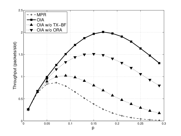
As explained in Section IV, the proposed OIA protocol consists of transmit beamforming as a PHY layer technique and interference-aware opportunistic random access as a MAC layer technique. In order to analyze the contribution of each technical component for overall throughput enhancement (also the overall effect by joint design of two components), we introduce two interference management protocols which exploit only one of the two technical components of the proposed OIA protocol. We term the OIA protocol without transmit beamforing at the PHY layer and the OIA protocol without opportunistic random access in the MAC layer as ‘OIA w/o TX-BF’ and ‘OIA w/o ORA’, respectively. Fig. 7 compares throughputs of MPR, ‘OIA w/o TX-BF’, ‘OIA w/o ORA’, and the proposed OIA protocols. In Fig. 7, is set to . The considered ‘OIA w/o TX-BF’ and ‘OIA w/o ORA’ protocols outperform the MPR technique, while the effect of the SVD-based transmit beamforming on the overall throughput is shown to be more significant than that of the CDF-based opportunistic random access. Compared to the OIA protocol without opportunistic random access, which results in the maximum throughput of packets/slot, the proposed OIA yields throughput enhancement. In addition, the proposed OIA achieves thropughput improvement, compared to the OIA protocol without transmit beamforming, which results in the maximum throughput of packets/slot. It is found that the maximum throughput of the proposed OIA protocol is achieved in the larger transmission probability than the those of other schemes.
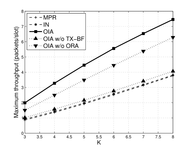
Fig. 8 shows the maximum throughput of the several considered protocols in this paper according to the number of overlapped RANs () when there exist users in each RANs (). We also assume the numbers of transmit and receive antennas as well as the dimension of signal space at APs are identical to the number of overlapped RANs, i.e., . The maximum throughput of each protocol is evaluated by searching all possible transmission probabilities. From Fig. 8, we observe that the effect of the opportunistic random access at the MAC layer on the maximum throughput is marginal. However, the effect of the opportunistic random access at the MAC layer on the maximum throughput becomes significant when it combines with the transmit beamforming at the PHY layer of the proposed OIA protocol. Note that both the SVD-based transmit beamforming and the CDF-based opportunistic random access play a role of reducing the interference among overlapped RANs. From Fig. 8, we can conclude that performance gain from the opportunistic random access in the MAC layer can be magnified in conjunction with the SVD-based transmit beamforming in the PHY layer. For example, the proposed OIA protocol achieves throughput improvement, compared to the MPR technique when .
VI Conclusion
In this paper, we proposed a novel interference management protocol called opportunistic interference alignment (OIA) for overlapped random access networks operating with slotted ALOHA, which intelligently combines the interference alignment based transmit beamforming technqiue at the PHY layer and the opportunistic random access technique at the MAC layer. We also introduced a simple extension method of the conventional techniques for interference-limited RANs: multipacket reception and interference nulling. The proposed OIA protocol is shown to significantly outperform the conventional schemes in terms of MAC layer throughput. The proposed OIA protocol is expected to be applied to next-generation wireless LANs such as IEEE 802.11 HEW without significant modifications. We leave this issue for further study.
References
- [1] http://www.ieee802.org/11/Reports/hew_update.htm
- [2] S. A. Jafar and M. J. Fakhereddin,“Degrees of freedom for the MIMO interference channel,” IEEE Trans. Inf. Theory, vol. 53, no. 7, pp. 2637-2642, Jul. 2007.
- [3] C. Suh and D. N. C. Tse, “Interference alignment for cellular network,” Allerton Conference on Communication, Control and Computing, pp. 1037-1044, 2008.
- [4] X. Chen and C. Yuen, “Performance analysis and optimization for interference alignment over MIMO interference channels with limited feedback,”IEEE Trans. Signal Process., vol. 62, no. 7, pp. 1785-1795, Apr. 2014.
- [5] B. C. Jung and W.-Y Shin, “Opportunistic interference alignment for Interference-Limited Cellular TDD Uplink,” IEEE Commun. Lett., vol. 15, no. 2, pp. 148-150, Feb. 2011.
- [6] H. J. Yang, W.-Y Shin, B. C. Jung, and A. Paulraj, “Opportunistic interference alignment for MIMO interfereing multiple-access channel,” IEEE Trans. Wireless Commun., vol. 12, no. 5, pp. 2180-2192, May 2013.
- [7] J. Leithon, C. Yuen, H. A. Suraweera, and H. Gao, “A new opportunistic interference alignment scheme and performance comparison of MIMO intereference alignement with limited feedback,” IEEE GLOBECOM, pp. 1123-1127, Dec. 2012.
- [8] H. Gao, J. Leithon, C. Yuen, and H. A. Suraweera, “New uplink opportunistic interference alignment: An active alignment approach,” IEEE WCNC, pp. 3099-3104, Apr. 2013.
- [9] Y. Ren, H. Gao, C. Yuen, and T. Lv, “Intra-cell performance aware uplink opportunistic interference alignment,” IEEE WCNC, 2014.
- [10] S. Gollakota, S. D. Perli, and D. Katabi, “Interference alignement and cancellation,” ACM SIGCOMM2009, pp. 159-170, 2009.
- [11] K. C.-J. Lin, S. Gollakota, and D. katabi, “Random access heterogeneous MIMO network,” ACM SIGCOMM2011, pp. 146-147, 2011.
- [12] V. Pourahmadi, A. S. Motahari, and A. K. Khandani, “Degrees of freedom of MIMO-MAC with random access,” IEEE Trans. Commun., vol. 61, no. 5, May 2013.
- [13] H. Jin, B. C. Jung, H. Y. Hwang, and D. K. Sung, “A MIMO-based collision mitigation scheme in uplink WLANs,” IEEE Commun. Lett., vol. 12, no. 6, pp. 417-419, Jun. 2008.
- [14] H. Jin, B. C. Jung, and D. K. Sung, “A tradeoff between single-user and multi-user MIMO schemes in multi-rate uplink WLANs,” IEEE Trans. Wireless Commun., vol. 10, no. 10, pp. 3332-3342, Oct. 2011.
- [15] C.-S Hwang and J. M. Cioffi, “Opportunistic CSMA/CA for achieving multi-user diversity in wireless LAN,” IEEE Trans. Wireless Commun., vol. 8, no. 6, pp. 2972-2982, Jun. 2009.
- [16] H. Jin, B. C. Jung, and V. C. M. Leung, “Fundamental limits of CDF-based scheduling: Throughput, fairness, and feedback overhead,” IEEE Trans. Netw., To Appear.