On the Effect of I/Q Imbalance on Energy Detection and a Novel Four-Level Hypothesis Spectrum Sensing
Abstract
Direct-conversion transceivers are in demand, due to low
implementation cost of analog front-ends. However, these
transmitters or receivers introduce imperfections such as in-phase
and quadrature-phase (I/Q) imbalances. In this paper, we first
investigate the effect of I/Q imbalance on the performance of
primary system, and show that these impairments can severely degrade
the performance of cognitive radio system that are based on
orthogonal frequency division multiplexing (OFDM) multiple access
scheme. Next, we design a new four-level hypothesis blind detector
for spectrum sensing in such cognitive radio system, and show that
the proposed detector is less vulnerable to I/Q imbalance than
conventional two-level detectors.
Index Terms— Cognitive radio,
I/Q imbalance, blind detection, fading channels, OFDMA
I Introduction
Cognitive radio is a promising approach to alleviate the spectrum scarcity faced by today wireless communication systems. The spectrum utilization has been noticed to be less than in practice [1], and thus leads to the idea of reusing spectrum by a secondary network[2]. In a cognitive radio network, secondary or unlicensed users benefit by opportunistically accessing the spectrum, while primary or licensed users are protected from the interference.
The recent development in integrated circuit (IC) technology and incorporation of complete phase-locked loop devices in low-cost IC packages have made direct-conversion transceivers widely accepted. Nevertheless, in contrary to their desirable characteristics, the implementation of direct-conversion transceivers causes various impairments associated with the analog components. The in-phase and quadrature-phase (I/Q) imbalance has been known as a major source of analog impairments in high-speed wireless communication systems[3].
The effect of I/Q imbalance on traditional communication systems have been comprehensively investigated in previous works [4, 5, 6, 7, 8, 9, 10], and various compensation algorithms have been proposed [11, 12, 13, 14]. However, many of the proposed algorithms cannot be applied to cognitive radio systems. For instance, a compensation method for I/Q distortions based on a novel pilot pattern is proposed in[14]. Since there is no cooperation between the primary transmitter and the secondary receiver in a cognitive radio network, this method and other algorithms evolved out of channel estimation techniques are not applicable in a cognitive radio system. Although the negative effects of I/Q imbalance can be severe, there has not been sufficient studies on the impact of I/Q imbalance in cognitive radio system, and the way to mitigate it. In [15, 16], Neyman-Pearson detector [17] have been exploited to perform spectrum sensing in the presence of transceiver I/Q imbalance. Our work differs as we propose a multi-level detector and study the problem through minimum average cost detection [18] criterion.
In this paper, we consider the effect of interference imposed by I/Q imbalance on the performance of the primary system with blind spectrum sensing at the secondary user. By blind spectrum sensing, we mean that the secondary user does not have access to the instantaneous channel state information of the primary link, which is the same assumption as in [19]. In order to tackle the effects of I/Q imbalance, we propose a four-level hypothesis blind detector for the first time, and compare the performance of the proposed detector to the conventional two-level detector under the scenario of I/Q imbalance impaired transceivers.
The subsequent sections of this paper are organized as follows. Section II describes the system model under the effect of I/Q imbalance and explains the idea of utilizing periodogram detector. In Section III, we analyze the effects of secondary transmitter I/Q imbalance on outage probability of the primary system. In Section IV, we explain how I/Q imbalance can affect the spectrum sensing by the secondary user. A four-level hypothesis blind detector is proposed to address the problems of I/Q imbalance, and the detection problem is formulated. Section V compares the performance of the new detector with conventional two-level detectors. Conclusion is given in Section VI.
II System Model
We consider a cognitive radio network where the primary system utilizes OFDMA technique for its uplink transmission. We assume an overlay cognitive radio system in which the secondary user should not interfere with primary user channels and access only vacant channel. The primary system consists of primary users and dedicates total number of subcarriers to them. Each primary user transmits a set of designated data symbols for and , where is taken from an M-PSK symbol constellation and only one user transmit on a single subcarrier, i.e., orthogonal multiuser transmission. Without loss of generality, we discard the user index u, since we assume the same modulation scheme for all primary users, i.e., M-PSK symbol constellation. The average power of each subcarrier is assumed to be , . We assume that no data is transmitted on the direct current (DC) subcarrier and K is an even number. The cyclic prefix is assumed to be longer than the impulse response of the channel and hence, there is no inter-carrier interference. In addition, we assume that the secondary user knows a priori information about potential primary systems including frame structure, subcarrier structure like the Discrete Fourier Transform (DFT) size, the transmission parameters (fundamental symbol rate, cyclic prefix length), and the level of interference tolerance of primary systems [20]. After removing the cyclic prefix and DFT operation, the channel in the subcarrier k can be represented as a complex channel , which is modeled as Rayleigh fading with independent Gaussian distributed random variable of variance . It has been shown that I/Q imbalance in OFDM-based systems results in a mutual interference between subcarriers that are located symmetrically to the DC carrier [21, 22]. In this paper, we focus on transmitter’s I/Q imbalance, since the direct-conversion architecture is commonly employed in transmitters[23]. We assume that both primary and secondary direct-conversion transmitters are wideband, in which the inter user interference imposed by I/Q imbalance is probable.
In practice, there is neither ideal amplitude matching nor exact phase difference among I and Q signals. Thus, the actual transmitted signal , which is different from the ideal transmitted signal, can be modeled as [24]:
| (1) |
where denotes the complex conjugate. Moreover, the signals sent by primary users are assumed to be normalized, i.e., . From (1), at the primary transmitter, there is an interference induced by I/Q imbalance, which can be a significant performance limiting factor, especially in the mobile uplinks. The degree of I/Q imbalance can be evaluated in terms of an image rejection ratio (IRR), which is defined by and for transmitter and receiver, respectively [25]. Parameters and in (1) are two complex scalars given by
| (2) |
and and represent the amplitude and phase mismatch of transmitter I/Q signals, respectively [26]. In addition, and are defined based on (2), but with respect to the receiver mismatch parameters. From now, we use subscripts and to differentiate between the transmit I/Q imbalance parameters of the primary user and that of the secondary user, respectively. From (1), the received signal at secondary receiver can be written as
| (3) |
where is the noise with independent and identically distributed (i.i.d.) Gaussian distribution with zero mean and variance , i.e., .
A typical energy detector consists of a low pass filter to remove the out-of-band noise and adjacent interference, an analog to digital converter, as well as a square law device to compute the energy. However, this implementation computes the energy of signal within the entire frequency band that is not a preferable approach to perform the spectrum sensing[27]. Hence, a periodogram solution is proposed in[27], which is depicted in Fig.1. In this figure, indices and represent the time domain and frequency domain, respectively.
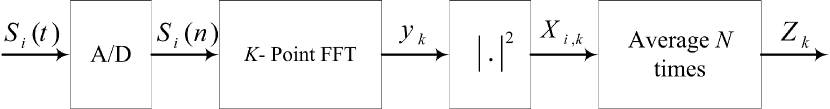
From (3), the output of periodogram detector is given by
| (4) |
where and denote real and imaginary parts of , respectively. In addition, variables and represent the number of time-domain data packets and the square-law detector’s output for the i-th data packet of k-th subcarrier, respectively.
III I/Q Imbalance Effect on Primary System Performance Metric
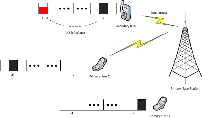
In this section, we analyze the effect of interference imposed by secondary user on the performance of primary system. This interference occurs due to the I/Q imbalance of the secondary user transmitter. Fig. 2 demonstrates a cognitive radio network with an OFDMA uplink transmission of primary users. Meanwhile, the secondary user senses subcarrier k in order to decide if it is vacant. In this example, neither primary user 1 nor primary user 2 transmits data on subcarrier k, while the primary user 2 transmits over subcarrier -k. The two-level energy detector’s decision for subcarrier is based only on the signal’s averaged power in -th subcarrier. In fact, although the secondary user may be aware of the transmit I/Q imbalance, it just incorporates the information derived from the -th output of the FFT block for deciding on subcarrier , regardless of the state of subcarrier . Hence, if the secondary user uses two-level detector for spectrum sensing, it would transmit over subcarrier k, then as a result, primary user 2 would be impaired by the I/Q imbalance from secondary user. As shown in Fig. 2, the secondary transmission on an idle subcarrier, e.g. subcarrier , introduces an interference on subcarrier . The primary receiver treats the secondary interference as noise. Hence, the received signal at the primary receiver is
| (5) |
where denotes the channel coefficient of the primary link on subcarrier , is the transmitted power of the secondary user, and is secondary signal on subcarrier . Moreover, is the additive Gaussian noise of the primary receiver with zero mean and variance of , i.e., and is independent of channel coefficients.
Assuming a primary uplink transmission with a fixed transmission rate of , the outage probability is defined as [28]. From (5), and by considering the normalized bandwidth, the data rate is given by
| (6) |
where denotes the signal to interference plus noise ratio (SINR). The outage probability can then be expressed as , where . Hence,
| (7) |
where and are two exponential random variables with mean and , respectively. Therefore, the outage probability at the primary receiver can be calculated as
| (8) |
IV Four-Level Hypothesis Test for I/Q Imbalance Impaired Spectrum Sensing
In this section, we introduce a four-level hypothesis test, and apply Bayesian minimum average cost criterion to this model[18]. To understand the motivation of the proposed four-level hypothesis test, again consider the scenario depicted in Fig. 2.
In addition to the problem discussed in previous section, I/Q imbalances imposed by primary users can make a secondary user assume a vacant subcarrier busy. This would rise the probability of false alarm and degrades the system performance. Therefore, we use this notion to propose a four-level hypothesis test, where the detector can adjust the decision thresholds more intelligently and detect vacant subcarriers more precisely. We model the four possible cases that could happen at a secondary receiver as follows:
The first state occurs when the secondary user receives only noise and there is no data transmission by any of the primary users in both k-th and -k-th subcarriers. The second state happens when there is transmission in subcarrier -k by one of the primary users, while subcarrier k is left vacant. Hence, the secondary user senses the interference plus noise, where the interference is due to the I/Q imbalance of secondary receiver or primary transmitter or both of them. If primary user transmits in subcarrier k, then secondary user senses only primary signal plus noise as stated by the third hypothesis. The forth state stands for the transmission of data over both k-th and -k-th subcarriers by primary users. Therefore, at this state the secondary user receives a signal associated with the k-th subcarrier and also an interference plus noise.
The proposed detector is able to differentiate the interference imposed by mirrored subcarrier from the main signal, i.e., by detecting . This is important, because secondary user can use this group of subcarriers in case that secondary transmitter does not suffer from considerable I/Q imbalance. Even for the secondary user with high transmit I/Q imbalance, this detector helps user to be aware of the primary transmission on subcarrier and avoid interfering with primary system. According to the four-level hypothesis model and the expression for the received signal from (3) and (4), the hypothesis test can be formulated as
| (9) |
From (3), it is obvious that the received signal is a complex random variable. Hence, where
| (10) |
and and represent real and imaginary parts of , respectively. It can be checked from (IV) that real and imaginary parts of are Gaussian random variables with zero mean and identical variances. In addition, and are uncorrelated [29]. Hence, they are independent and can be represented as a complex Gaussian random variable. Thus, the probability density function of their square is given by[30]
| (11) |
where and denote the probability density function of variable and the variance of either real or imaginary part of , respectively. In addition, considering the fact that and are independent, and from (11), the probability density function of is
| (12) |
From (IV), the conditional probability density function of can be represented as exponential distribution as follows:
| (13) |
where and
| (14) |
The periodgram detector, introduced in Section II, computes the average of FFT output for N time domain windowed data packets for each frequency slot. The overall output of the detector for each frequency slot is a Gamma distributed random variable, since it is a sum of N exponential random variables with identical means, i.e., . Therefore, we have
| (15) |
where is the gamma function[31, Sec. (8.31)].
Now, we apply the minimum average cost criterion to this model. Without losing any generality, a uniform cost test with equal prior probabilities is assumed for all hypotheses. Thus, is selected if[18]
| (16) |
It can be shown that by applying the conditions in (16), four decision regions are obtained as follows:
| (17) |
where is the corresponding region of each hypothesis and
| (18) |
In Appendix A, it is shown that , , and . Thus, the expressions in (17) can be simplified as:
| (19) |
In order to analyze the effect of I/Q imbalance, we calculate the probability of false alarm, i.e., when there is no signal transmission in subcarrier k , but secondary user assumes that the channel is busy. Equivalently,
| (20) |
From (15), the integrals can be evaluated using the following:
| (21) |
where is the incomplete gamma function[31]. Therefore, from (IV) and (IV) the probability of false alarm can be expressed as
| (22) |
Similarly, the probability of detection is given by
| (23) |
It must be noted that different side information is needed in order to calculate the detection thresholds. For instance, the statistics of the interference link between primary users and secondary users, i.e. , could be inferred by listening to the downlink transmission of the primary system[28]. In addition, the determination of primary transmitter IRR values or transmit power requires either explicit signaling from the primary system to the secondary users, or the primary transmit power could be estimated if secondary user roughly knows about its distance from the nearby primary user. This work could also be extended to MIMO systems in which localization and other array-antenna techniques are incorporated.
V Simulation Results
In this section, we provide simulations to evaluate the analytical results provided in previous sections. We assume a cognitive radio network with an OFDMA primary system with four users, i.e., . Moreover, the total number of subcarriers is , i.e., 128 subcarrier per user with 16-PSK constellation. We also assume a secondary user that uses blind detection for spectrum sensing, based on the four-level hypothesis test proposed in Section IV. The magnitude of the frequency domain channel coefficients and are assumed independent Rayleigh distributed random variables with variance . In order to examine the statistical aspects of energy detector, simulations are done over 20 million samples and for one sample package, i.e., . Here, we define the transmitted signal to noise ratio for subcarrier and as and , respectively. We consider orthogonal signaling, hence interference is only due to the I/Q imbalance. Secondary receiver treats primary interference as the Gaussian noise, since it is not completely aware of the primary signal’s modulation parameters. The SNR at each subcarrier can be determined by priodogram detector described in Section II.
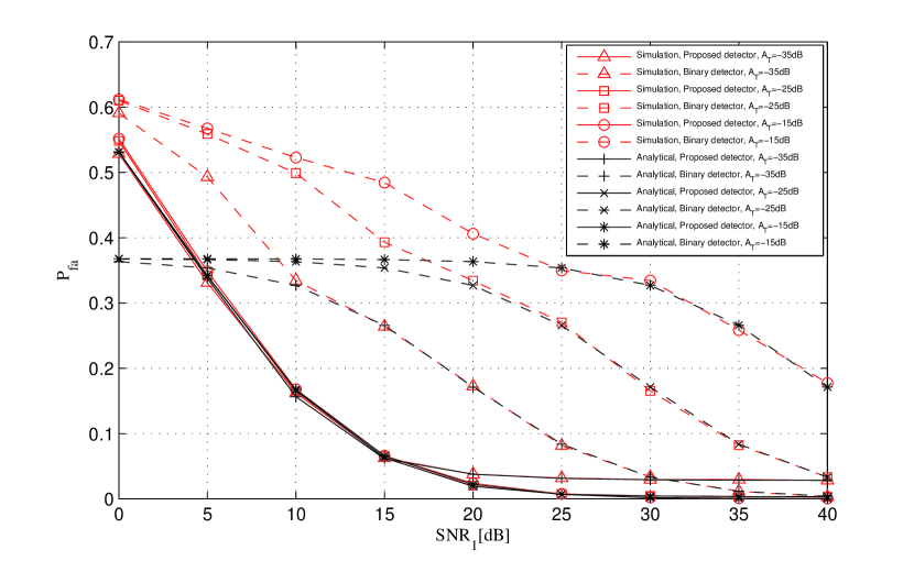
The comparison between the proposed four-level detector and the conventional two-level detector is shown in Fig.3. Based on the results, the proposed detector is less vulnerability to the I/Q imbalance effect than the two-level detector. Since the two-level detector sets its detection threshold based only on the estimated noise variance, the interference imposed by other subcarriers can fool the detector. On the other hand, the proposed detector uses the joint information of both subcarriers and , by adding hypotheses and into its detection procedure. This helps the detector to sense the spectrum based on the variance of both noise and interference which leads to lower probability of false alarm.
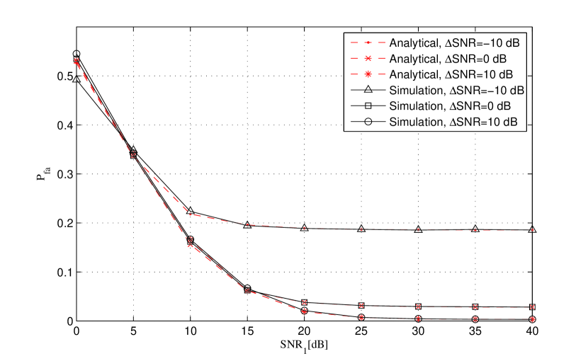
Fig.4 demonstrates both analytical and simulation results of I/Q imbalance effect on probability of false alarm for the proposed detector by considering various , which denotes the signal to noise ratio difference between the subcarriers and . Fig.4 shows that even for , the probability of false alarm is significantly increased.
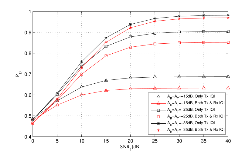
The comparison of joint transmitter-receiver I/Q imbalance effect on the probability of detection with the case when I/Q imbalance exists only in transmitters is shown in Fig. 5. The joint transmitter-receiver I/Q imbalance effect can be investigated based on the procedure introduced in this paper. Indeed, it can be proven that the variance of received signal may differ from that of presented in Section IV, nevertheless the detector output distributions are identical in both scenarios. Hence, the probability of false alarm and the probability of detection could be found accordingly. As expected from analytical results, effect of I/Q imbalance on the receiver’s probability of detection is serious when direct-conversion transceivers are used. However, direct-conversion receivers offer significant power saving, hence they might be as preferable as direct-conversion transmitters to be utilized in wireless communication devices[23].
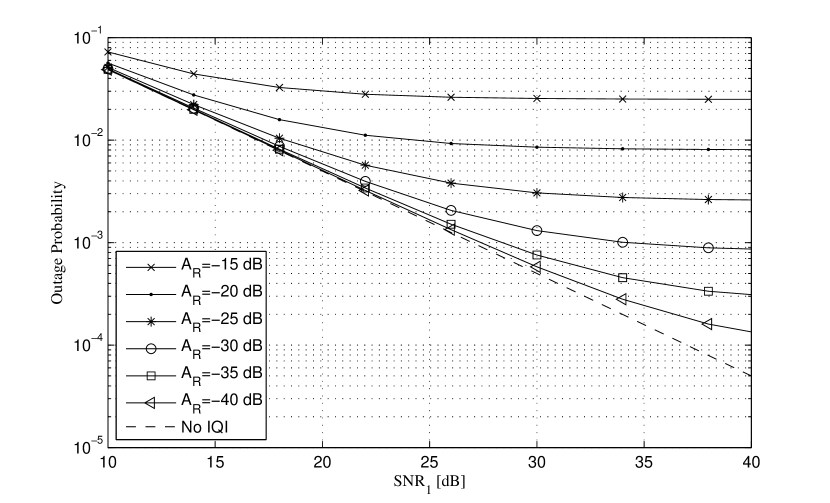
Eventually, Fig. 6 depicts the impact of I/Q imbalance of the secondary transmitter on the outage probability of primary receiver. It clearly demonstrates that the I/Q imbalance in secondary transmitter can dramatically affect the performance of the primary system.
VI Conclusion
In this paper, the effects of I/Q imbalance on both primary and secondary systems have been investigated. It was explained how I/Q imbalance can make the secondary user interfere to an OFDMA primary system if the secondary user employs binary detector. Therefore, we design a new detector based on four-level hypothesis for blind spectrum sensing in an overlay cognitive radio system. The detection algorithm jointly considers the information of DFT blocks output for a specific subcarrier and the interference imposed by its symmetrical counterpart. Simulation results show that the proposed detector decreases the probability of false alarm, while avoids interfering to primary system.
APPENDIX A
From (14) and assuming as well as , it is obvious that . Moreover, from (18), we have
| (24) |
where . Therefore, (APPENDIX A) suggests that is of the form of differentiation, i.e., , which is a decreasing function of . Hence, , , and .
References
- [1] Federal Communication Commissions, Facilitating Opportunities for Flexible, Efficient, and Reliable Spectrum use Employing Cognitive Radio Technologies. in FCC-03-322, 2003.
- [2] F. K. Jondral and T. A. Weiss, “Spectrum pooling: An innovative strategy for the enhancement of spectrum efficiency,” IEEE Radio Communications, vol. 42, no. 3, pp. S8–S14, March 2004.
- [3] C. L. Liu, “Impact of I/Q Imbalance on QPSK-OFDM-QAM Detection,” IEEE Trans. Consumer Electron., vol. 44, no.8, pp. 984–989, Aug. 1998.
- [4] A. Tarighat and A. H. Sayed, “MIMO OFDM receivers for systems with I/Q imbalances,” IEEE Trans. Signal Process., vol. 53, no.9, pp. 3583–3596, Sep. 2005.
- [5] M. Krondorf and G. Fettweis, “Ofdm link performance analysis under various receiver impairments,” EURASIP Journal on Wireless Communications and Networking, DOI:10.1155/2008/145279, 2008.
- [6] F. Lopez-Martinez, E. Martos-Naya, J. F. Paris, and J. Entrambasaguas, “Exact closed-form BER analysis of OFDM systems in the presence of IQ imbalances and ICSI,” IEEE Transactions on Wireless Communications, vol. 10, no.6, pp. 1914–1922, Jun. 2011.
- [7] Y. Zou, M. Valkama, N. Ermolova, and O. Tirkkonen, “Analytical performance of OFDM radio link under RX I/Q imbalance and frequency-selective Rayleigh fading channel,” in Proc. IEEE Int. Workshop on Signal Processing Adv. Wireless Communications (SPAWC11), (San Francisco, CA), Jun. 2011.
- [8] S. Mallick and S. Majumder, “Performance analysis of an OFDM system in the presence of carrier frequency offset, phase noise and timing jitter over Rayleigh fading channels,” in Proc. IEEE International Conf. Electrical Computer Engineering, pp. 205–210, Dec. 2008.
- [9] R. Zhang, E. Au, and R. Cheng, “Impacts of CFO, IQ imbalance and phase noise on the system performance of OFDM systems,” in IEEE Int. Conf. on Communication Systems, pp. 1041–1045, Nov. 2008.
- [10] S. Krone and G. Fettweis, “Capacity analysis for OFDM systems with transceiver I/Q imbalance,” in Proc. IEEE GLOBECOM, pp. 1–6, Nov. 2008.
- [11] Y. Yoshida, K. Hayashi, H. Sakai, and W. Bocquet, “Analysis and compensation of transmitter IQ imbalances in OFDMA and SC-FDMA systems,” IEEE Trans. Signal Process., vol. 57, no. 8, pp. 3119–3129, Aug. 2009.
- [12] M. Valkama, A. Shahed, L. Anttila, and M. Renfors, “Advanced digital signal processing techniques for compensation of nonlinear distortion in wideband multicarrier radio receivers,” IEEE Trans. Microw. Theory Tech., vol. 54, no. 6, pp. 2356–2366, Jun. 2006.
- [13] J. Tubbax, B. Come, L. V. der Perre, S. Donnay, M. Moonen, and H. D. Man, “Compensation of transmitter I/Q imbalance for OFDM systems,” In Proc. IEEE Int. Conf. Acoust., Speech, Signal Process. (ICASSP), pp. 325–328, 2004.
- [14] H. A. Mahmoud, H. Arslan, M. K. Ozdemir, and F. E. Retnasothie, “I/Q imbalance correction for OFDMA uplink systems,” In Proc. IEEE Int. Conf. Commun. (ICC), Jun. 2009.
- [15] A. ElSamadouny, A. Gomaa, and N. Al-Dhahir, “Likelihood-based spectrum sensing of OFDM signals in the presence of Tx/Rx I/Q imbalance,” IEEE Global Communications Conference (GLOBECOM), Anaheim, CA, vol. 57, no. 4, pp. 3616–3621, Dec. 2012.
- [16] A. Gokceoglu, S. Dikmese, M. Valkama, and M. Renfors, “Enhanced energy detection for multi-band spectrum sensing under rf imperfections,” 8th International Conference on Cognitive Radio Oriented Wireless Networks (CROWNCOM), Washington, DC, pp. 55–60, July 2013.
- [17] S. M. Kay, Fundamentals of Statistical Signal Processing: Detection Theory. Princton, NJ, 1998.
- [18] H. Vincent Poor, An Introduction to Signal Detection and Estimation. Princton, NJ, 1994.
- [19] P. De and Y. C. Liang, “Blind spectrum sensing algorithms for cognitive radio networks,” IEEE Trans. Veh. Technol., vol. 57, no. 5, pp. 2834–2842, Sep. 2008.
- [20] K. C. Cheng and R. Prasad, Cognitive Radio Networks. John Wiley & Sons, 2009.
- [21] T. C. Schenk, E. Fledderus, and P. F. Smudlers, “Performance Analysis of Zero-IF MIMO OFDM Transceivers with IQ Imbalance,” Journal of Communications, vol. 2, no. 7, pp. 9–19, Dec. 2007.
- [22] Y. Zou, M. Valkama, and M. Renfors, “Analysis and Compensation of Transmitter and Receiver I/Q Imbalances in Space-time Coded Multiantenna OFDM Systems,” EURASIP Journal on Wireless Communications and Networking, doi:10.1155/2008/391025, 2008.
- [23] A. A. Abidi, “Direct-conversion radio transceivers for digital communications,” IEEE Journal of Solid-State Circuits, vol. 30, no. 12, pp. 1399–1410, Dec. 1995.
- [24] B. Maham and O. Tirkkonen, “Transmit Antenna Selection OFDM Systems with Transceivers I/Q Imbalance,” IEEE Trans. Commun., vol. 60, no. 3, pp. 643–648, Mar. 2012.
- [25] B. Maham and A. Hjorungnes, “Impact of Transceiver I/Q Imbalance on Transmit Diversity of Beamforming OFDM Systems,” IEEE Trans. Veh. Technol., vol. 61, no. 2, pp. 865–871, Feb. 2012.
- [26] B. Razavi, RF Microelectronic. Englewood Cliffs, NJ: Prentice-Hall, 1998.
- [27] D. Cabric, A. Tkachenko, and R. W. Brodersen, “Spectrum Sensing Measurements of Pilot, Energy, and Collaborative Detection,” Proceeding of IEEE Military Communication Conference (MILCOM), Oct. 2006.
- [28] B. Maham, R. Popovski, X. Zhou, and A. Hjoungnes, “Cognitive Multiple Access Network with Outage Margin in the Primary System,” IEEE Transactions on Wireless Communications, vol. 10, no.10, pp. 3343–3353, Oct. 2011.
- [29] L. Anttila, M. Valkama, and M. Renfors, “Circularity-based I/Q imbalance compensation in wideband direct-conversion receivers,” IEEE TRANSACTIONS ON VEHICULAR TECHNOLOGY, vol. 57, no. 4, pp. 2099–2113, July 2008.
- [30] M. K. Simon, Probability Distributions Involving Gaussian Random Variables: A Handbook for Engineers, Scientists and Mathematicians. Springer-Verlag New York, Inc., Secaucus, NJ, 2006.
- [31] I. S. Gradshteyn and I. M. Ryzhik, Table of Integrals, Series, and Products. San Diego, CA: Academic, 2000.