Low latency protocol for transmission of measurement data from FPGA to Linux computer via 10 Gbps Ethernet link
Abstract
This paper presents FADE-10G – an integrated solution for modern multichannel measurement systems. Its main aim is a low latency, reliable transmission of measurement data from FPGA-based front-end electronic boards (FEBs) to a computer-based node in the Data Acquisition System (DAQ), using a standard Ethernet 1 Gbps or 10 Gbps link. In addition to transmission of data, the system allows the user to send reliably simple control commands from DAQ to FEB and to receive responses.
The aim of the work is to provide a possible simple base solution, which can be adapted by the end user to his or her particular needs. Therefore, the emphasis is put on the minimal consumption of FPGA resources in FEB and the minimal CPU load in the DAQ computer. The open source implementation of the FPGA IP core and the Linux kernel driver published under permissive license facilitates modifications and reuse of the solution.
The system has been successfully tested in real hardware, both with 1 Gbps and 10 Gbps links.
keywords:
FPGA, Ethernet, Ethernet Protocol, Data Acquisition, Measurement System1 Introduction
In modern multichannel measurement systems, it is often necessary to transfer multiple data streams from detectors to computers responsible for processing of data. Especially the introduction of a triggerless approach in High Energy Physics (HEP) experiments ([1, 2, 3, 4]) increased demand on the amount of data that must be transferred to the Data Acquisition (DAQ) System, and therefore also on the number of links that must be provided. The Front End Boards (FEB) are typically built using FPGA chips, which nowadays are often equipped with gigabit or multi-gigabit transceivers. That enables the implementation of a broad range of high-speed communication interfaces [5, 6]. When selecting the appropriate solution, we must take into account additional requirements like a length of the link (which in some experiments may reach even a few hundred meters [7]) and an electrical insulation (so optical fiber is preferred). To reduce the total cost of implementation of multiple links, we should use a standard interface to benefit from price reduction thanks to the mass production of transceivers and other components of the link infrastructure.
Considering the requirements mentioned above, it seems that the Ethernet link, using the SFP or SFP+ optical transceivers is the optimal solution. Broad use of the Ethernet technology has resulted in a significant reduction in the price of components (namely SFP+ transceivers) needed to implement the 10 Gbps Ethernet link both on the computer side and on the FPGA side. The achievable price of an optical 10 Gbps SFP+ transceiver is approximately $85 for a single channel. It can be further reduced when ordering a bigger batch, or when using four channel QSFP+ transceivers (price approximately $280 for four channels).
1.1 Required functionality of the transmission system
The aim of this work is to create a minimal but extensible solution. Therefore, it is important to define the requirements that should be fulfilled by such a system.
-
•
Possibility to work with 1 Gbps (for price-sensitive applications) and 10 Gbps (for typical applications) Ethernet links
-
•
Reliable transport of data stream with maximal throughput and minimal latency (because the latency directly affects the amount of memory needed to buffer transmitted but not yet confirmed data).
-
•
Possibility to control FEBs and to check their status from the DAQ side of the link (even though in a typical DAQ system there is yet another separate communication channel for configuration and diagnostics of FEBs).
-
•
Open source implementation, that may be modified to suit the needs of the particular experiment.
-
•
Ability to work with different PHY interfaces (copper or optical), depending on the needs of the particular experiment.
2 State of the art
The standard solution for the reliable transfer of data via an Ethernet network is the TCP/IP protocol. Unfortunately, this protocol has serious disadvantages when used in an FPGA. It has been optimized mainly for the transport of data in wide area networks with multiple routers between communicating devices. Therefore, it contains many features related to routing of data packets, fragmenting the packets and with sharing the link bandwidth between multiple connections. The TCP/IP also assumes that data may be transported via untrusted networks, and therefore it implements sophisticated algorithms protecting the communication against malicious activity. The final result is that implementation of the full TCP/IP stack in an FPGA is complex and resource hungry. Some implementations rely on a CPU implemented in an FPGA or embedded in an FPGA [8], but such solutions do not allow full utilization of the 10 Gbps link throughput. There are some commercial implementations of 10 Gbps hardware TCP/IP stacks for an FPGA, but they are closed and expensive solutions [9, 10].
2.1 Reduced TCP/IP developed at CERN
An interesting attempt to reduce resource consumption of the hardware-based TCP/IP implementation is a solution developed at CERN and described in [11, 12]. The authors have reduced the functionality of the TCP/IP so that it is possible to implement it in an FPGA without implementing any soft CPU core. The implementation provides only unidirectional transmission. The authors did not implement timestamps, selective acknowledgments or out of band data. In addition, certain mechanisms have been significantly simplified – e.g. the congestion management. This solution however still relies on the external DDR memory used as a TCP socket buffer. The advantage of this solution is that the receiver may be a standard computer with TCP/IP stack provided by the operating system. However, this solution also leads to significant CPU load. As the authors state themselves “Running one 10 Gbps TCP stream can easily saturate one of the CPU cores.”
Another significant disadvantage is the closed source nature of this solution. No sources have been released, so it can not be a basis for an open, extensible solution.
2.2 Avoiding the TCP/IP complexity
To avoid the implementation of a complex TCP/IP stack in the FPGA and to reduce the load of CPU in the receiving computer, it is desirable to use a simpler protocol. Usage of the UDP protocol instead of TCP is not optimal. The UDP protocol does not assure reliable transfer of data, so it is necessary to implement additional mechanisms ensuring reliability. At the same time, the UDP protocol and all IP protocols still require significant overhead associated with the routing of packets (datagrams).
 |
However, the connection between FEBs and DAQ should not contain any routers, as they increase link latency, which in turn leads to an increase of memory needed to buffer the transmitted and not yet confirmed data.
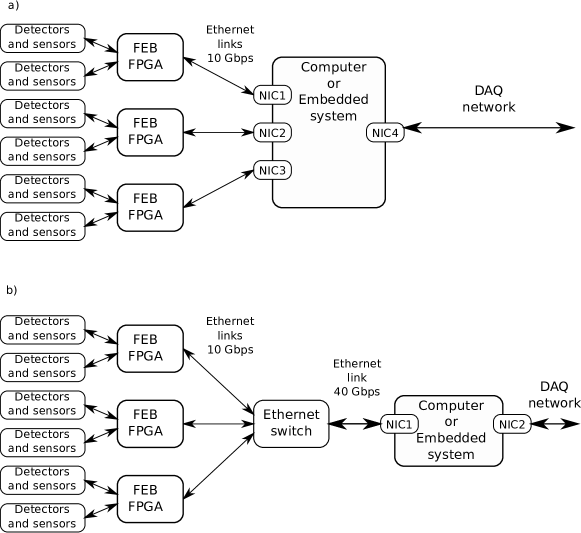
There are two possible link topologies. In the case where Ethernet interfaces in both – FEBs and DAQ computers have the same speed the point-to-point connections will be used (see Figure 1a). If the Ethernet interface in the DAQ computer offers a higher speed (e.g. 40 Gbps), it is possible to connect a few FEBs to a single network card via a 10 Gbps/40 Gbps switch (see Figure 1b). For such very simple networks, where Ethernet frames are passed either directly or via a Layer 2 network switch, the best solution is to develop an optimized Layer 3 protocol using raw Ethernet frames.
2.3 Ethernet Proxy – EPRO as possible solution
The protocol and Linux kernel driver based on the above assumptions was developed at the AGH University of Science and Technology and described in [13, 14]. The proposed solution implements not only a reliable transport of the data stream, but also some additional functions. Those functions include different types and priorities of data, or the possibility to send the same data to more than one destination. The protocol is implemented for a 1 Gbps link and uses the standard Xilinx MAC implementation. Unfortunately, this solution like the previous one is not open. The authors did not publish sources, so it is not possible to modify it to work with higher speed 10 Gbps links or to adjust it to the particular experiment’s requirements.
2.4 First version of the FADE protocol
Another possible solution is the author’s open source FADE protocol described in [15]. This protocol provides reliable transmission of data from an FPGA to a computer through 1 Gbps Ethernet links. The resource consumption in the FPGA is kept to a minimal level and may be adjusted using a parametrized VHDL code. Instead of a complex standard MAC, simplified state machines are used to receive and send packets. These are sufficient for full-duplex Ethernet links with granted link bandwidth. The initial version of the FADE protocol worked correctly with 1 Gbps links, but an attempt to simply modify the FPGA IP core for operation with 10 Gbps Ethernet PHY revealed problems with efficiency. Therefore, the whole code was significantly modified. Modifications included simplification of the packets management. For example, the concept of “sets of packets” described in [15] was dropped in favor of a simple description of the data stream as a continuous sequence of packets. Another modification was the addition of the possibility to perform simple control and diagnostic operations via the Ethernet link while the original FADE protocol allowed only to send START and STOP commands.
This article describes the implementation of the new version of the FADE protocol named FADE-10G.
3 Implementation of the FADE-10G protocol
The FADE-10G protocol is aimed at the transmission of the continuous data stream consisting of 64-bit words. To better utilize the link bandwidth, data are transmitted using Ethernet jumbo frames. The data packets contain 1024 data words (8192 bytes) and some additional information (MTU should be set to 9000 in the network interface configuration). The number of data words in a packet equal to the power of two was chosen to simplify packet management both in the FPGA and in the receiving computer, as it is described later. When the transmission is stopped, the last packet may contain fewer data words. In such a case, the last data word contains the number of valid words in that packet (between 0 and 1023). Because the protocol is supposed to be used as the only protocol in private networks, the private, unofficial Ethertype 0xfade is used. To differentiate frames of the FADE-10G from the old FADE frames, and to allow further modifications of the protocol, the protocol version number is transmitted after the Ethertype field. This number is equal to 0x0100 in the current version111In the first version of the FADE protocol, this field contained the type of the frame and could be a value from the range 0x01 to 0x05 or the value 0xa5a5.. Because the Ethernet link does not warrant the reliable delivery of frames, it is necessary to implement a simple acknowledgment/retransmission algorithm, which uses special shorter acknowledgment frames. Still others short frames are necessary to allow transmission of simple control or diagnostic commands via Ethernet link. The general structure of the FADE-10G Ethernet frame is shown in Table 1, and the payload contained in frames of different types is shown in Table 2.
| Standard Ethernet header | Protocol version | Payload | Filler | Checksum | ||
|---|---|---|---|---|---|---|
| Source MAC | Destination MAC | 0xFADE | 0x0100 | Payload bytes | N*0xa5 | FCS |
| 6 bytes | 6 bytes | 2 bytes | 2 bytes | length depends on the type of frame | variable length used when the frame is too short | 4 bytes |
| a) Data acknowledgment frame (from computer to FPGA) | ||||||||||||||
|---|---|---|---|---|---|---|---|---|---|---|---|---|---|---|
|
||||||||||||||
| b) User command request (from computer to FPGA) | ||||||||||||||
|
||||||||||||||
| c) Standard data packet (from FPGA to computer) | ||||||||||||||
|
||||||||||||||
| d) Last data packet (from FPGA to computer) | ||||||||||||||
|
||||||||||||||
| e) Command response packet (from FPGA to computer) | ||||||||||||||
|
||||||||||||||
| Command response field in the data packet or command response packet: | ||||||||||||||
|
3.1 Implementation of the protocol in the FPGA
The reliable transmission of data via an unreliable channel (like an Ethernet link) requires retransmission. Therefore, it is necessary to buffer the data that have been transmitted, but have not yet been confirmed by the receiving computer.
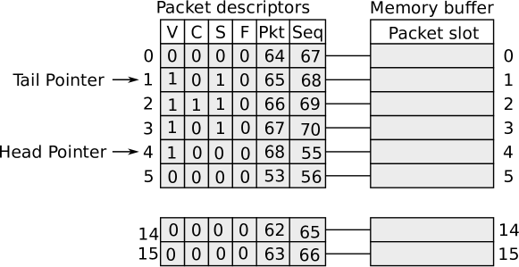
To keep the algorithm controlling the retransmission as simple as possible, the memory buffer in the FPGA has a length of data packets. Each data packet is 1024 words (8192 bytes) long. Thus, the lower bits of the number of the data packet in the data stream may be directly used to define its position in the memory buffer. The length of this buffer also defines the transmission window of the protocol. At every moment, only a packet from a certain set of consecutive packets may be transmitted via the link. The value may be configured before synthesis of the core and compilation of the protocol driver (described in Section 4).
Each packet is associated with its descriptor shown in Figure 2.
 |
The structure of the IP core implemented in the FPGA is shown in Figure 3. The Ethernet Receiver and Ethernet Sender blocks are simple state machines, replacing the standard Ethernet MAC. They are connected to the external Ethernet PHY or the internal Ethernet PHY equivalent implemented in the FPGA – like the Xilinx PCS/PMA core [16].
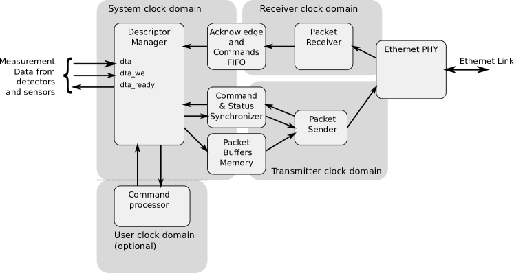 |
64-bit data words provided by the data source are written to the data packet pointed by the Head pointer. When this packet is filled, it is marked as ready for transmission (V=1). Then the Descriptor Manager checks if it is possible to move the Head pointer to the next position. If the next position is the one pointed by the Tail pointer, it means that the buffer is full. In this case, the ready status of the core is deasserted until the packet pointed by the Tail pointer is acknowledged, and the Tail pointer is moved to the next position.
The Ethernet Receiver block receives packets, checks their checksum, and writes information from correctly received packages to the Acknowledgment and Commands FIFO (Ack & Cmd FIFO). Additionally, the Ethernet Receiver itself executes a few high priority commands like START, STOP, and RESET. The START and STOP commands are still written to the Ack & Cmd FIFO to ensure generation of their confirmation. The RESET command causes the reset of the whole FADE-10G core and is therefore not confirmed at all.
The Descriptor Manager reads commands from the Ack & Cmd FIFO. If the received command is the packet acknowledgment (ACK) or negative packet acknowledgment (NACK), the Descriptor Manager handles it itself, as these commands are not confirmed. Other commands are passed to the Command Processor, which executes the command and generates their confirmation.
The packet acknowledgment (ACK) command sets the C (Confirmed) flag in the descriptor
of the acknowledged packet if this packet is still kept in the buffer222It is possible that the core receives a delayed duplicated
acknowledgment packet. In that case, the buffer
no longer contains the corresponding descriptor..
If the received ACK packet contains a packet number bigger than the number
of the last transmitted packet333The packet number wraps every packets. Therefore comparison of those
numbers is defined as follows:
if ., a protocol error is detected.
After all commands available from the Ack & Cmd FIFO are executed the Ethernet Receiver block tries to move the Tail pointer freeing all packets that have the C flag set in their descriptor. All flags in descriptors of freed buffers are cleared. After that operation, if there is a free place in the buffer, the ready status of the core is asserted again.
Another activity performed by the Descriptor Manager is the transmission and retransmission of packets. It continuously browses the packet buffer and finds packets that have the V flag set, but the C flag unset. Those packets are passed to the Ethernet Sender block for transmission or retransmission.
The last hardware block is the Command Processor, which may work in the same clock domain as the Descriptor Manager but may also operate in another (even its own) clock domain. The Command Processor executes the received command and after the result or status is ready it builds the command response and passes it to the Descriptor Manager. The command response is then transmitted either in the nearest data packet or the dedicated command response packet (if no data packet is currently waiting for transmission or retransmission).
The core counts transmitted data packets and retransmitted data packets to avoid network congestion or computer overload. The ratio of those counts is then calculated. If the detected ratio of retransmitted packets is too high which may be a symptom of an overload, the delay between transmitted packets is increased. If the ratio of retransmitted packets is very small, this delay is decreased. Thresholds used by the delay adaptation algorithm are parametrized and may be changed before synthesis of the core. For debugging purposes, current transmission delay is included in packets sent from the FPGA to the computer (field Transmission Delay in Table 2).
3.2 Early retransmission mechanism
The retransmission algorithm described has one significant disadvantage. If the packet pointed by the Tail pointer (or its acknowledgment) is lost, the space in the packet buffer will not be freed until this packet is retransmitted again and successfully confirmed. In the described implementation, this packet will be only retransmitted after all other pending packets are transmitted or retransmitted. Therefore, the core will not accept new data for a significant amount of time.
The performance of the algorithm may be improved, if such a packet is retransmitted as soon as its loss (or loss of its acknowledgment) is detected. The clear sign of such an event is when the core receives acknowledgment of the packet that has been transmitted after that one. Such a solution is similar to the “Fast retransmit” used in the TCP protocol [17].
In the simplest solution after reception of the acknowledgment of any packet all unconfirmed packets with the packet number smaller than the one received will be retransmitted.
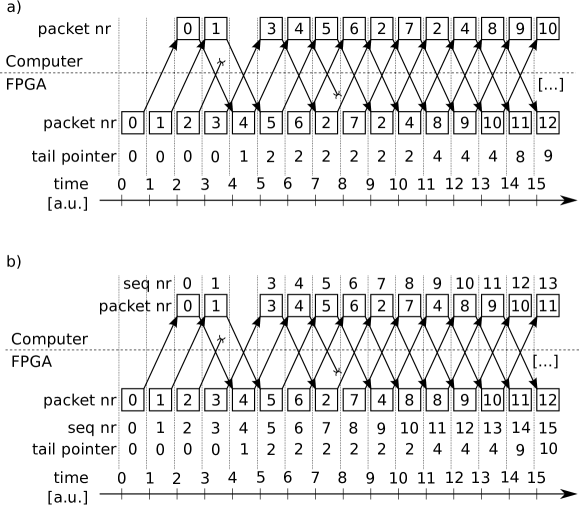 |
Unfortunately, this kind of simplistic implementation based only on the number of the packet in
the data stream is not optimal. If loss of yet another packet is detected before the “early retransmitted” packet is confirmed this packet will be unnecessarily retransmitted
once again (see Figure 4a). To prevent this, the data packets are labeled additionally with
the frame sequence number incremented after every transmission.
The last frame sequence number used to transmit the particular data packet is stored
in the packet’s descriptor (the “Seq” field in Figure 2).
This frame sequence number is copied to the acknowledgment packet.
When loss of the packet is detected, it is possible to retransmit early only those
packets that have a last frame sequence number smaller444The frame sequence number wraps every packets. Therefore comparison of those
numbers is defined as follows:
if .
than the acknowledgment packet
just received (see Figure 4b).
3.3 Execution of user commands
To ensure that each command is delivered reliably, executed exactly once and its results are delivered successfully to the computer, the command sequence numbers (CSNs) are used.
Whenever a new command is sent to the FPGA core, the CSN is increased. That enables discarding of possible duplicated responses to previous commands. After a new command is sent, the computer waits for the response for a certain configurable amount of time. If the computer does not receive the command response packet in the declared time period, it states that either the command packet or the response packet were lost. In that case, the computer resends the same command once again.
When the FPGA core correctly receives the command packet it first checks its CSN. If it is the same as in the last serviced command (which means that the response packet was lost, and command was resent), the core only resends the response for that last command. If the CSN is different, the core stores it, executes the command and then sends the response packet with the same CSN.
The command response is sent in the pending data frame if it is available or (when currently no data packet is waiting for transmission or retransmission) in the dedicated command response packet (see Table 2 c–e).
3.4 Resource consumption
| FPGA chip and buffer length | Resource | Used units | Available units | The percentage of usage |
| Kintex 7 xc7k32tffg900-2 | Slices | 801 | 50,950 | 1.57% |
| Slice LUTs | 2,107 | 203,800 | 1.03% | |
| Slice registers | 1,240 | 407,600 | 0.3% | |
| BRAM tiles | 65 | 445 | 14.6% | |
| Kintex 7 xc7k32tffg900-2 | Slices | 756 | 50,950 | 1.48% |
| Slice LUTs | 2,065 | 203,800 | 1.01% | |
| Slice registers | 1234 | 407,600 | 0.3% | |
| BRAM tiles | 33 | 445 | 7.42% | |
| Spartan 6 xc6slx45csg324-2 | Slices | 611 | 6,822 | 8.96% |
| Slice LUTs | 1599 | 27,288 | 5.86% | |
| Slice registers | 1227 | 54576 | 2.25% | |
| BRAM blocks | 68 | 116 | 58.6% |
The FADE-10G core supporting 10 Gbps links was successfully synthesized for the Kintex 7 xc7k325tffg900-2 FPGA used in KC705 [18] and AFCK [19] boards. The version supporting 1 Gbps links was successfully synthesized for the Spartan 6 xc6slx45csg324-2 FPGA used in Atlys boards [20]. Synthesis for the Kintex 7 FPGA was performed for two sizes of the memory buffer ( and ). Due to the limited amount of internal memory synthesis for the Spartan 6 FPGA was performed only with . Results of the synthesis are presented in Table 3. It is visible that the FADE-10G core leaves a reasonable amount of logic resources available for the user to implement FEB blocks. For the xc7k325tffg900-2 can easily accommodate the FADE-10G core operating four 10 Gbps links. For the same chip can work with even eight such links.
4 Linux driver
GNU/Linux is widely used in modern data acquisition systems. As a free and open source system, it is a perfect platform for such an open solution as the one proposed in this paper.
Because FADE-10G uses a non-standard Ethernet protocol, it is necessary to implement a dedicated kernel driver as a protocol handler responsible for the reception of the Ethernet frames of type 0xfade. Similarly to the solutions described in [13] and [15], the protocol handler is installed using the dev_add_pack function. Whenever the Ethernet frame with 0xfade type is received, the callback function in the driver is called.
The driver may service one or more FPGA-based FEBs. They can be connected to separate Ethernet cards, or (via a switch) to the same Ethernet card (see Figure 1). Each connected FPGA-based FEB is serviced via a dedicated character device (/dev/l3_fpga%d, where %d is replaced with subsequent numbers starting from 0). The maximum number of serviced FEBs is declared when loading the driver using the max_slaves parameter. The character device may be opened and configured for communication with the FPGA (slave) using the particular MAC address. After that a slave context is created, describing the state of communication with that slave. One of the components of the slave context is the receiver packet buffer, which stores received data. The amount of memory available in the computer is significantly higher than the amount of internal memory in the FPGA. Therefore, this buffer may be much longer than the memory buffer in the FPGA core (which has a length of packets as described in Section 3.1). Its length is chosen to be packets. Thus, the lower bits of the packet number in the data stream may be directly used as the number of the corresponding packet slot in the receiver packet buffer. That is a circular buffer with the Head pointer and the Tail pointer pointing respectively to the next byte to be written and to the last byte not yet read.
4.1 Packet reception routine
The callback function my_proto_rcv is called when the packet of 0xfade type is received. It first checks if the packet arrived from the correct (“opened”) FEB. If not, the driver sends a “reset” command to the misbehaving FEB. If the correct FEB slave is found, further operations are performed on the slave context of that FEB.
The function checks the protocol version. If it is incorrect, the appropriate error flag is set, and the packet is dropped. Then the type of the received packet is checked. If it is a command response packet, and if there is a thread waiting for completion of this command, the result is copied from the packet to the user-space buffer. Then the waiting thread is woken up, and the function returns. If the packet is neither a response packet nor a data packet, the error flag is set, and the packet is dropped.
If none of the above conditions applies, the packet is handled as a data packet. First the function checks the command response section. If there is a thread waiting for the completion of the corresponding command, the result is copied to the user space. Then the waiting thread is woken up (like in the case of a dedicated command response packet). Afterward, the data part of the packet is handled. The receiver packet buffer stores the 32-bit packet number of the last received and confirmed packet for each packet slot. The number of the received packet in the data stream (see Table 2) is compared to the packet numbers of packets currently stored in the receiver packet buffer. If the packet is already received and confirmed, or if the packet is “older”555The “age” of packets is checked by subtracting their numbers modulo . The result below is considered to be a positive number. than packets in the buffer, it is assumed that the confirmation was possibly lost. In this case, the function simply marks that the packet should be confirmed once again. If the packet is “newer” than the packets in the current transmission window, it means that a protocol error has occurred – the function sets the appropriate error flag and drops the packet. If none of the above conditions applies, the packet contains new, unconfirmed data. The length of the packet is verified, and the function checks if there is enough free space in the receiver packet buffer. If not, it drops the packet (it will be retransmitted again by the FEB). If there is enough free space, data from the packet is copied to the corresponding packet slot.
If the received packet is the “last unconfirmed”, the routine updates the Head pointer. After that if the amount of data available in the buffer is higher than the “receiver wake-up threshold” set by the user application, the receiving thread is woken up. If the received packet it the “last data packet” (see Table 2d), the last packet flag is also set. If the last packet flag is set and all packets are confirmed, the “end of transmission” flag is set, and the receiving thread is also woken up to receive the last part of data. In each case, if required, the confirmation packet is prepared and scheduled for transmission.
4.2 Communication with the user application
To avoid conflicts when controlling different slaves, each character device (/dev/l3_fpga%d) may be open only once, by one application. However, the user application may perform two different activities: reception of data and sending of control commands. Commands are serviced in a synchronous way and the thread sending the command is put to sleep until the command is executed, and the response is received. When the data is transmitted at high speed, it is unacceptable to stop the data reception until the command is executed. Therefore, the user application should start an additional thread after opening the device so that the reception and processing of data and the execution of control commands are handled in separate threads.
To avoid overhead associated with copying data, the receiver packet buffer for each slave should be mapped into the appropriate application’s memory using the driver’s mmap function. Therefore, the data is copied only once from the socket buffer delivered by the Network Interface Card (NIC) driver to the shared kernel receiver packet buffer666There are technologies offering the true zero copy handling of network data like “Direct NIC Access” [21] or “PF_RING ZC” [22]. However it is not clear whether they can be used to create a continuous representation of the received data in the user application memory without additional copying. The PF_RING ZC still requires single copying of the data when used with a standard NIC.. Of course, the access to such shared memory must be appropriately synchronized. That is achieved using the ioctl function. The driver implements a set of ioctl commands summarized in Table 4.
| IOCTL code | Description of the commands |
|---|---|
| L3_V1_IOC_SETWAKEUP | Sets the amount of data bytes that must be available in the circular buffer before the user-space application is woken up. |
| L3_V1_IOC_GETBUFLEN | Returns the length of the circular buffer associated with a particular FEB. |
| L3_V1_IOC_READPTRS | Returns the number of available data bytes and the positions of the Head pointer and Tail pointer in the circular buffer associated with a particular FEB. Provides necessary synchronization when accessing the pointers. |
| L3_V1_IOC_WRITEPTRS | Should be called with the number of bytes processed by the application. Provides necessary synchronization and updates the Tail pointer in the circular buffer associated with a particular FEB. |
| L3_V1_IOC_GETMAC | Associates the FEB identified by the given MAC and connected to the given network interface with the particular character device. |
| L3_V1_IOC_STARTMAC | Starts the transmission from the previously associated FEB. |
| L3_V1_IOC_STOPMAC | Stops the transmission from the FEB associated with the particular character device. |
| L3_V1_IOC_FREEMAC | Disassociates FEB from the particular character device. |
| L3_V1_IOC_RESETMAC | Resets the FADE-10G core in the FEB associated with a particular character device. |
| L3_V1_IOC_USERCMD | Sends the user command to the FEB associated with a particular character device. This command puts the current thread to sleep until the command is executed, and the result is sent back. |
4.2.1 Reception of data
The user application may read the current positions of the Head pointer and Tail pointer in its receiver packets buffer using the L3_V1_IOC_READPTRS ioctl command. This command ensures appropriate synchronization so that the stable Head pointer values are read. Additionally, this command returns the number of available bytes in the receiver packet buffer. To avoid active waiting for data, the application may define (with the L3_V1_IOC_SETWAKEUP ioctl command) how many bytes of data must be available in the receiver packet buffer before the receiver thread is woken up. The thread will be woken up also when the transmission finishes, even if the number of available bytes is below the defined threshold.
4.2.2 Sending the user commands
When sending a user command, the user fills the structure containing the code of the command, its argument, the number of retries and the timeout for each retry. Those parameters allow the user to adjust the behavior of the driver to the expected time of execution of the command. The pointer to this structure is used as the second argument to the ioctl call. When the ioctl L3_V1_IOC_USERCMD is executed, the current thread is put to sleep until the command response is received or until the timeout expires. In the latter case, the command is resent until the given number of retries is reached. Together with the functionalities of the FPGA core described in subsection 3.3, this implementation ensures correct single execution of the command, even if either the command packet or response packet gets lost.
5 Tests and results
The FADE-10G protocol was tested in different scenarios. The operation at 1 Gbps was verified using an Atlys board [20] and Dell Vostro 3750 (Intel Core i7-2630QM CPU with 2.0 GHz clock). 10 Gbps operation was verified using the KC705 board [18] and a computer equipped with an Intel Core i5-4440 CPU with 3.10 GHz clock. Operation with four 10 Gbps links was verified with an AFCK board [19] equipped with an FMC board with 4 SFP+ cages. The board was connected to a computer equipped with an Intel Xeon CPU E5-2630 v2 with 2.60 GHz clock.
Correctness of transmission was tested with the FPGA core sending a preprogrammed sequence of data that was later verified by the receiving computer. Transmissions up to 10 Tb were tested, and no transmission errors occurred. The achievable transmission speed was equal to 990.34 Mbps with 1 Gbps interface in the Atlys board.
In tests of maximum transmission speed with 10 Gbps links, it was found that verification of data led to a decrease of the achievable throughput. The user application was not able to process data at the full speed, and the congestion avoidance algorithm was activated. Therefore, the maximum throughput tests were performed without a full data verification. Tests with the 10 Gbps interface in the KC705 board demonstrated a throughput of 9.815 Gbps. However to achieve such a throughput it was necessary to decrease receive interrupt latency in the network adapter with the “-C rx-usecs 0” command of the ethtool program. With a standard interrupt latency of 1 s, the achievable throughput was equal to only 6.5 Gbps.
The CPU load was measured with the top program. The load during the transmission via a single link (without data verification) was measured on the computer with an Intel Core i5 CPU. The result was equal to 2.15% (0.97% in user processes, 0.31% in system processes and 0.87% in software interrupts).
Operation with four 10 Gbps links in the AFCK board working simultaneously has shown limitations related to the computer speed. The achieved mean throughput was equal to 9.72 Gbps per link. With full data verification, the throughput was further limited to 8.88 Gbps per link. The CPU load measured during the transmission through four links without verification was equal to 3.90% (0.10% in system processes and 3.80% in software interrupts; load in user processes was reported as 0%). The measurements were performed on the computer with an Intel Xeon CPU.
In the final measurement system, the data delivered to the memory mapped buffer should be split into records to be routed to computers in the DAQ network. With the appropriate organization of the readout format, the separation of records should not require checking of each received word. Therefore, it is expected that the CPU load related to the routing of data should be significantly lower than the load generated by the full data verification. Furthermore, transmission of records to the DAQ network via modern NICs should be done using the DMA with minimal CPU load. However, implementation of the readout protocol and the data routing application is beyond the scope of this paper as a responsibility of the end user.
In summary, the presented test results suggest, that the FADE-10G system should allow reception and routing of one 10 Gbps data stream with a computer with an Intel Core i5 CPU, and 4 such streams with a computer with an Intel Xeon CPU.
Of course, the CPU computational power is not the only bandwidth limiting factor. When designing the system, it is necessary to consider throughput of all I/O interfaces involved in the transfer of data. To check the behavior of the FADE-10G system in conditions where the output channel limits the overall bandwidth, another set of tests was performed with the user application writing the data directly to the SATA SSD disk. In this setup, the throughput was limited by the disk. The throughput achieved was the same as for the application storing the pre-generated pseudorandom data to the disk. The congestion avoidance algorithm has correctly limited the transmission rate from the FPGA core. The data stored on the disk was later analyzed, and no corrupted data were discovered.
The last series of tests verified transmission of the user commands in the worst conditions. The dedicated application transmitted user commands during reception of the continuous stream of data. In the 1 Gbps setup, the FPGA core was able to execute 2870 commands per second with data transmission speed unaffected. In the 10 Gbps setup, the FPGA core was able to execute ca. 40000 commands per second without impairing the transmission speed.
The protocol has been optimized for operation at high data rate. For lower data rates, there is a danger that data may wait too long until the data packet is completed and transmitted. To avoid this, the data source should provide a minimum flow of data (e.g. “time stamps” or “dummy data”) in the low data rate conditions. That ensures that the delay, associated with the completion of the data packet, is acceptable. This approach keeps the protocol as simple as possible but requires the user to enforce the minimal required data flow in the upper layer. As that additional data is inserted only in low traffic conditions, its removal in the receiver application should not significantly increase the CPU load. The alternative solution could be sending incomplete packets after a user defined timeout. Such a packet could have a similar payload as the “last packet”, shown in Table 2d, but should be marked as another packet type (e.g. 0xa5a7). Unfortunately, handling such packets at the receiver side would break the idea of an efficient, transparent passing of the received data stream into the memory buffer directly available for the user application and would result in a drop of efficiency at a high data rate.
6 Conclusions
The presented FADE-10G system allows reliable transmission of measurement data from an FPGA via a 1 Gbps or 10 Gbps interface to a computer running Linux OS. The system can almost fully utilize the link throughput. Apart from transmission of data, the system implements simple control or diagnostic commands, which are reliably transmitted to the FPGA. The results of the command execution are also reliably transferred to the computer. Even with a fully occupied link the system executes over 2800 commands per second with 1 Gbps link, and ca. 40000 commands per second with 10 Gbps link. The system minimizes packet acknowledgment latency that in turn allows the reduction of the amount of memory needed in the FPGA to buffer the data. Additionally, the system implements a special “early retransmission” mechanism, which reduces the latency of the data retransmission in case of a lost packet. The data received by the computer is delivered to the user application using the memory mapped kernel buffer, that avoids unnecessary data copying and reduces the CPU load.
The FADE-10G system is implemented in a possibly simple way and published under permissive licenses (most parts under BSD license, some under GPL license and some as public domain). Therefore, it can be a good base solution for further development of a transmission system suited to a particular experiment. Sources of the FADE-10G project are available on the OpenCores website [23].
Acknowledgements.
The author thanks Dr Grzegorz Kasprowicz and Dr Dawid Rosołowski from Warsaw University of Technology for providing access to the hardware needed to test the FADE-10G system with 10 Gbps Ethernet links.References
- [1] R. Karabowicz, An event building scenario in the trigger-less PANDA experiment, J. Phys.: Conf. Ser. 513 (2014), no. 1 012016.
- [2] F. Alessio, Trigger-less readout architecture for the upgrade of the LHCb experiment at CERN, \jinst82013C12019 (2013).
- [3] J. de Cuveland, V. Lindenstruth, and the CBM Collaboration, A first-level event selector for the CBM experiment at FAIR, J. Phys.: Conf. Ser. 331 (2011), no. 2 022006.
- [4] S. Bachmann et al., The proposed trigger-less TBit/s readout for the Mu3e experiment, \jinst92014C01011 (2014).
- [5] Altera, Transceiver portfolio, 2015. http://www.altera.com/technology/high_speed/hs-index.html .
- [6] Xilinx, High speed serial, 2015. http://www.xilinx.com/products/technology/high-speed-serial.html .
- [7] D. Hutter and J. de Cuveland, CBM readout and online processing overview and recent developments, 2013. https://www-alt.gsi.de/documents/DOC-2013-Apr-27-1.pdf .
- [8] LightWeight IP application examples, November, 2014. http://www.xilinx.com/support/documentation/application_notes/xapp1026.pdf .
- [9] 10GbE full-hardware TCP stack (TOE), 2015. https://www.plda.com/products/fpga-optimized-ip/10g-ethernet-ip-tcpudp/10gbe-full-hardware-tcp-stack-toe .
- [10] TOE 10G IPcore - TCP offloading engine IP core, 2014. http://www.dgway.com/TOE10G-IP_X_E.html .
- [11] G. Bauer et al., 10 Gbps TCP/IP streams from the FPGA for high energy physics, J. Phys.: Conf. Ser. 513 (2014), no. TRACK 1.
- [12] G. Bauer et al., 10 Gbps TCP/IP streams from the FPGA for the CMS DAQ eventbuilder network, \jinst82013C12039 (2013).
- [13] B. Mindur and L. Jachymczyk, The Ethernet based protocol interface for compact data acquisition systems, \jinst72012T10004 (2012).
- [14] B. Mindur and L. Jachymczyk, A general purpose Ethernet based readout data acquisition system, in IEEE Nucl. Sci. Symp. Med. Imag. Conf., pp. 800–806, Oct, 2011.
- [15] W. M. Zabolotny, Optimized Ethernet transmission of acquired data from FPGA to embedded system, in Proc. SPIE, vol. 8903, pp. 89031L–89031L–12, 2013.
- [16] 10 Gigabit Ethernet PCS/PMA (10GBASE-R), 2014. http://www.xilinx.com/products/intellectual-property/10GBASE-R.htm .
- [17] M. Allman, V. Paxson, and W. Stevens, TCP congestion control, April, 1999. RFC 2581 (Proposed Standard), http://www.ietf.org/rfc/rfc2581.txt.
- [18] Xilinx Kintex-7 FPGA KC705 evaluation kit, January, 2015. http://www.xilinx.com/products/boards-and-kits/ek-k7-kc705-g.html .
- [19] AMC FMC carrier Kintex (AFCK), October, 2014. http://www.ohwr.org/projects/afck/wiki .
- [20] Atlys™ Spartan-6 FPGA development board, September, 2012. http://www.digilentinc.com/Products/Detail.cfm?NavPath=2,400,836&Prod=ATLYS .
- [21] Direct NIC access, gigabit and 10 gigabit Ethernet line-rate packet capture and injection, 2015. http://www.ntop.org/products/pf_ring/dna/ .
- [22] PF_RING ZC (zero copy), multi-10 gbit RX/TX packet processing from hosts and virtual machines, 2015. http://www.ntop.org/products/pf_ring/pf_ring-zc-zero-copy/ .
- [23] Fade - light L3 Ethernet protocol for transmission of data from FPGA to embedded PC, December, 2012. http://opencores.org/project,fade_ether_protocol .