Development of a strontium optical lattice clock for the SOC mission on the ISS
Abstract
Ultra-precise optical clocks in space will allow new studies in fundamental physics and astronomy. Within an European Space Agency (ESA) program, the “Space Optical Clocks” (SOC) project aims to install and to operate an optical lattice clock on the International Space Station (ISS) towards the end of this decade. It would be a natural follow-on to the ACES mission, improving its performance by at least one order of magnitude. The payload is planned to include an optical lattice clock, as well as a frequency comb, a microwave link, and an optical link for comparisons of the ISS clock with ground clocks located in several countries and continents. Within the EU-FP7-SPACE-2010-1 project no. 263500, during the years a compact, modular and robust strontium lattice optical clock demonstrator has been developed. Goal performance is a fractional frequency instability below and a fractional inaccuracy below 5×10-17. Here we describe the current status of the apparatus’ development, including the laser subsystems. Robust preparation of cold 88Sr atoms in a 2nd-stage magneto-optical trap (MOT) is achieved.
I Introduction
The mission ACES (Atomic Clock Ensemble in Space) (Hess et al., 2011) will operate a cold-atom microwave clock on the ISS, with a planned flight date in 2016. A follow-on mission with an improved clock was proposed in 2005, in the framework of ESA’s ISS utilization program ELIPS. In this mission, the clock and the time/frequency links will have a performance at least a factor of 10 better than the ACES mission. An optical lattice clock (Poli et al., 2013) is a suitable solution for an improved clock. The payload will contain a frequency comb for transformation of the ultra-stable optical frequency into a microwave, in order to allow use of the microwave link technology for time and frequency transfer between Earth and ISS.
Since 2007, technical developments on a robust and compact Sr optical clock are being undertaken by the Space Optical Clock (SOC) consortium (www.soc2.eu) Important requirements for an optical clock for space are: performance, compact size and moderate mass, radiation hardness, fully automatic operation, low down-time, ability to withstand shocks and vibrations during launch (when in non-operational mode), and switch from non-operational to operational mode. These requirements led to the development of a first-generation breadboard system which successfully operated with 88Sr (Poli et al., 2014). Based on the experience gained with that system and its subunits, the development of an advanced breadboard system with improved specifications was initiated; its status is reported here. Earlier developments are reported in Ref. (Schiller et al., 2012)
II The SOC mission concept
The ISS mission SOC will implement two objectives in fundamental physics, the measurement of the gravitational redshift in the Earth’s field and in the Sun’s field. In addition, it will be operated as a reference clock in space, combined with a high-performance link allowing distribution of precise frequency over a large part of Earth and allowing comparisons between distant ground clocks of high performance, opening up the field of space-assisted relativistic geodesy.
The precise measurement of the gravitational redshift in the fields of two dissimilar bodies (the constitution of the atomic nuclei in the Earth and Sun being strongly different (mostly iron vs. hydrogen)) represents a search for the existence of new fundamental fields that induce a non-universality of the gravitational redshift effect. This implies a strong test of Einstein’s theory of General Relativity as well as of the Einstein Equivalence Principle. It also paves the way for future application of the redshift effect for high-accuracy mapping out the gravitational potential of planets or stars. In detail, the objectives of SOC are:
-
•
Objective I
The measurement of the gravitational redshift of the Earth will be performed with an accuracy improved by a factor 10 compared to the goals of the ACES mission. The improvement factor will be limited by the inaccuracy of the space optical clock () or of the link, since a sufficient number of primary terrestrial optical clocks having an accuracy higher than the space clock will be available by the time of the mission (Poli et al., 2013). -
•
Objective II
By comparing pairs of terrestrial clocks located at a large distance in east-west direction it is possible to perform a test of the equivalence principle in the gravitational field of the Sun (Hoffmann, 1961; Krisher, 1996). As any clock on the Earth is in free-fall with respect to the Sun (neglecting tidal forces), any relative frequency shift between two clocks caused by the Sun is expected to cancel. This is due to a cancellation between the pure gravitational effect and the relativistic Doppler shift occurring in a comparison between any two clocks located at a distance. Basically, the comparisons are performed in two orientations of the Earth: in one, the baseline between the terrestrial clocks is perpendicular to the direction to the Sun. This frequency comparison yields the difference in Earth’s gravitational potential between the two clock locations. The second orientation is when the clocks’ baseline lies parallel to the direction Earth-Sun. A measurement in this orientation contains a contribution of the Sun’s gravitational potential (solar redshift), but is canceled by the Doppler shift due to the motion of the clocks along the Earth orbit. In practice, the measurements will be performed continuously, for various orientations. Assuming ground clocks with accuracy of spaced one Earth radius away, and that a sufficiently large number of Earth rotations and comparisons is used to reduce the inaccuracy by a factor 10 compared to a single comparison, a measurement of the combined effect of solar redshift and Doppler shift with relative inaccuracy of can be obtained. The improvement compared to the mission ACES, which will also be capable of such a measurement, is a factor of 10 or more, limited by the inaccuracy that distant terrestrial clocks comparable via ACES will have achieved by the time of its flight, and by the ground-ISS link inaccuracy. -
•
Objective III
The Earth gravitational redshift is also the foundation for relativistic geodesy. Terrestrial clocks and corresponding receiver systems (occupying a volume on the order of a container or less) will eventually become available for transportation to locations of particular geophysical interest and can be compared to the space clock, allowing determination of the local value of the gravitational potential. These transportable clocks may well have reached an accuracy of by the time of the SOC mission. By relying on the goal inaccuracy of the space clock, the correctness of the gravitational redshift established by the mission, and precise ISS orbit determination, measurements of the local terrestrial gravitational potential at the equivalent uncertainty level of 10 cm would be possible. However, the space clock can also enable comparison of distant terrestrial clocks with accuracy compatible with clock inaccuracy after approximately 1 day of integration time, using an enhanced microwave link or the optical link. Thus, the differential gravitational potential between two terrestrial clocks may be measurable at the 1 cm uncertainty level. Tidal effects will have to be corrected for. Note that the relative resolution of the gravitational redshift of terrestrial clocks corresponding to this uncertainty level (1 cm relative to a few km maximum height difference) is on the order of several parts in , a level for which the correctness of the gravitational redshift will have already been tested by ACES. -
•
Objective IV
The dissemination of ultrastable frequencies over the Earth, where the frequencies are generated from both the space clock and a set of ultraprecise terrestrial clocks. This objective is foreseen to satisfy new future ground or space users. The measurement procedures will be similar to the ones of the other objectives. Thus, the SOC mission will contribute to link terrestrial clocks into a global network allowing ground-to-ground or ground to space comparisons with a relative frequency uncertainty level of .
III Overview

The transitions relevant for an optical lattice clock using strontium are shown in Fig. 1. 6 different laser wavelengths are necessary. The apparatus described here is modular and consists of (i) atom preparation unit, (ii) clock laser (698 nm), (iii) cooling laser (461 nm) with distribution unit, (iv) 2nd-stage cooling laser (689 nm), (v) stirring laser (689 nm), (vi) repumper lasers (679 nm, 707 nm), (vii) frequency stabilization system (FSS) (Nevsky et al., 2013). These subunits are interconnected by optical fibers. A computer system based on an field programmable gate array (FPGA) controls the system. A robust wavemeter would likely be part of the optical clock in space. However, the SOC consortium did not undertake a corresponding development. We describe the units in turn and present first characterization results.
IV Subunits of the Clock
IV.1 Atomics unit
The compact and lightweight vacuum chamber is shown in Fig. 2. Including the breadboard, the overall size is 143 liter and its mass is 50 kg. In the 3D MOT “science” chamber (right), an ultra-high vacuum in the range of 10-11 mbar is maintained. This is achieved by employing two ion pumps (25 l/s and 2 l/s), near to the atomic source and to the science chamber, respectively. In order to minimize the black-body radiation (BBR) coming from the atomic source during clock operation, an automated full-closure flag shutter is installed. Permanent magnets are used for the Zeeman slower, as low energy consumption is important. The Zeeman slower is described in detail in Ref. (Hill, Ovchinnikov, Bridge, Curtis, and Gill, 2014).
The science chamber, shown in Fig. 3, is very compact compared to usual chambers for optical lattice clocks. Nevertheless, it maintains robustness and is energy efficient. It weighs only 208 g, has 8 viewports and a total of 17 optical accesses: six for the MOT beams, one for the Zeeman slowing beam, two for the repump beams, two for the 1D lattice beams/interrogation beam, two for detection and four spare accesses for further detection methods. Six viewports have a clear access of 10 mm diameter, and two large viewports have a clear access of 34 mm diameter. Both of the latter contain five accesses each of 10 mm diameter. The viewports are made from BK7 glass, AR coated for all relevant wavelengths and sealed to the chamber using indium. The chamber is manufactured from titanium as its thermal expansion coefficient is similar to that of BK7 and it has favorable magnetic properties.
For a MOT field gradient of 4.5 mT/cm, the power dissipation per coil is less than 6 W, yielding a total dissipation of 12 W. At this level there is no need for active cooling of the coils. Instead, a multi-layer heat shield for the coils has been designed and implemented. This consists of two layers of copper separated by an insulating layer acting in order to reduce the heating effects of the MOT coils on the chamber (Figs. 1, 2). This heat shield could be actively temperature-controlled in the future, in order to reduce the clock uncertainty contribution due to BBR.
The atomic source is a low-power oven adapted from the device described in Ref. (Schioppo et al., 2012). The atomic beam deposits Sr atoms on the viewport of the 4-way cross after the 3D MOT chamber. In order to be able to remove the deposited strontium, a sapphire viewport was installed, which is bakeable to high temperature for that purpose.


IV.2 Laser system for the 1st-stage MOT
The 461 nm laser is a TOPTICA SHG-TA-PRO system (Fig. 4, left). It contains a 922 nm laser whose output is resonantly frequency-doubled in an enhancement cavity, emitting 400 mW. The output frequency is stabilized to the FSS (see below).
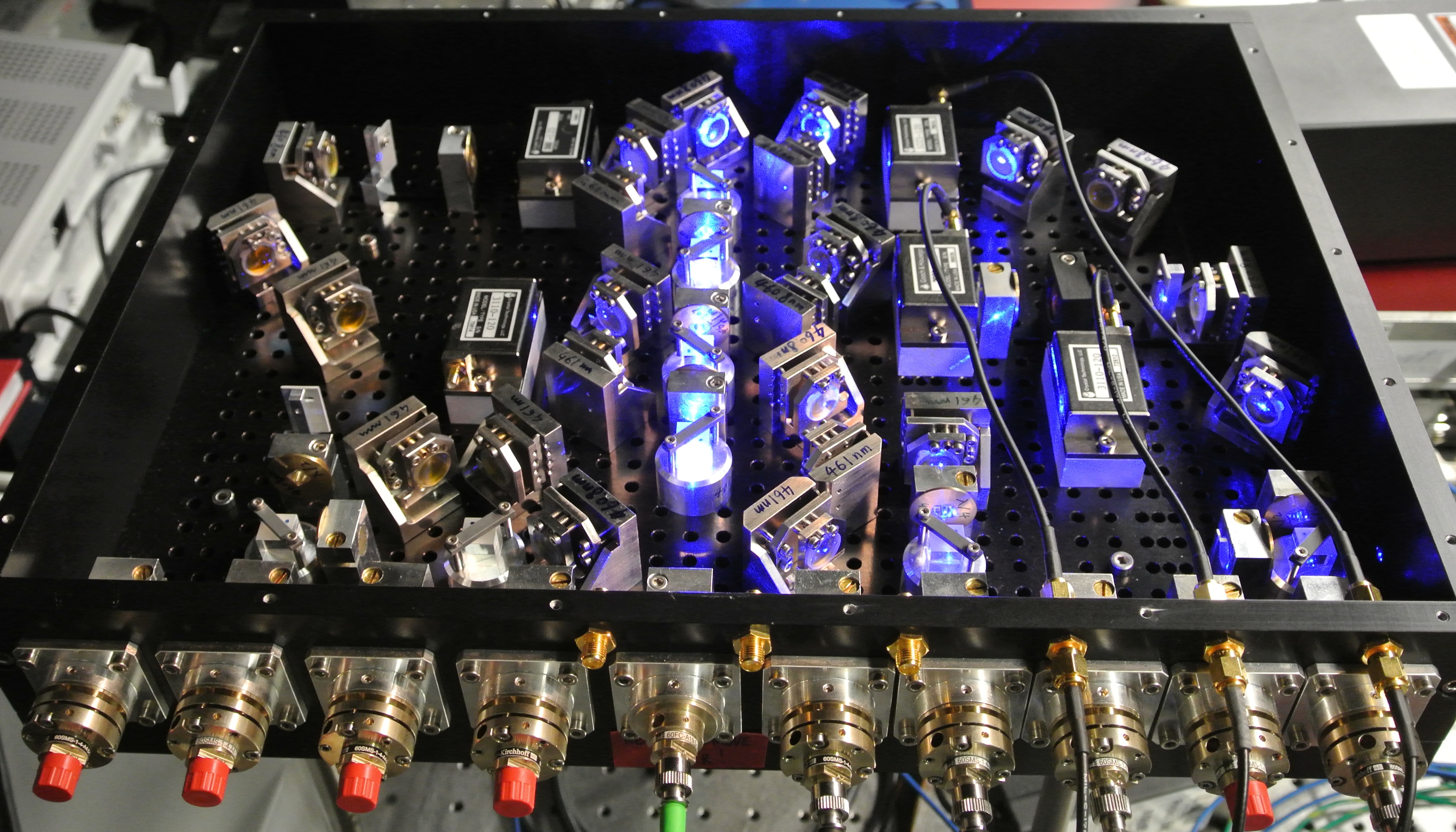
A compact and robust frequency distribution unit (Fig. 4, right) acts as an interface between the 461 nm laser and the atomics unit. The unit is of size 30 cm × 20 cm × 10 cm (6 liter) and mass 5 kg and has one fiber input for the 461 nm laser radiation and 9 fiber outputs, all of which are mounted on the same side, for ease of access. 250 mW laser power is available in the fiber input to the distribution unit. The fiber outputs are connected to the atomics unit.
The module can simultaneously supply required frequency (detuning) and intensity control for 2D & 3D MOTs, for the Zeeman slower, for detection and for spectroscopy that serves to lock the laser. It contains 5 acousto-optical modulators (AOMs) that can be controlled via a direct digital synthesizer (DDS), which itself can be interfaced with a computer.

IV.3 Lasers for the 2nd-stage MOT
The second-stage cooling employs the transition at 689 nm with a natural linewidth of about 7.5 kHz. In order to take full advantage of the correspondingly low Doppler temperature, a cooling laser with sub-kHz linewidth is required. We have observed that the spectral purity is especially important in the frequency range extending to 100 kHz around the carrier: sidebands or noise in this range can severely compromise the laser cooling and thus hamper the transfer efficiency of the atoms from the 2nd-stage MOT into the optical lattice. The spectral purity is typically achieved by a fast frequency lock to a highly stable optical reference resonator in combination with sufficiently small frequency noise of the free-running laser. Here, the FSS (Sec. IV.5) serves as such a reference. To cover a broad range of atomic velocities when capturing atoms precooled in the 461 nm MOT stage, during the first phase of the second-stage cooling, the laser spectrum is broadened by modulation of the frequency with peak-to-peak amplitude of 5MHz and modulation frequency of 30 kHz. In our design, the modulation is introduced within the frequency control servo loop to the reference cavity through frequency modulation of the sideband frequency in the FSS, thus avoiding the power consumption and complexity of a dedicated double-pass AOM on the laser breadboard. Furthermore, the 2nd-stage cooling of 87Sr requires not only one laser that addresses the cooling transition but a second (so-called stirring) laser to drive the hyperfine transition (Mukaiyama et al., 2003), which is detuned by about 1.4 GHz from the transition. The stirring laser must have similar spectral characteristics as the 2nd-stage cooling laser and it needs to follow the frequency modulation of the cooling laser that is applied during the initial phase of the 2nd-stage MOT operation.
The two compact 2nd-stage cooling laser pulse distribution breadboards are based on designs for the stationary Sr lattice clock at PTB, and use half-inch optical components. To keep the optical setup simple without requiring a second reference cavity, the stirring laser is phase-locked to the cooling laser using a beat note between both. The frequency of this beat note is at 1.4 GHz and is detected with an avalanche photodiode, integrated on the stirring laser board. The beat frequency is mixed with a reference frequency from the sixth harmonic of a 243 MHz DDS. A phase/frequency detector creates an error signal which is fed back to the piezoelectric transducer (PZT) (slow part) and the laser diode current (fast part, small corrections) of the stirring laser. The parameters of the phase-lock were optimized to obtain a unity-gain bandwidth of 500 kHz. In the setup, commercial lasers (TOPTICA DL-pro), with long extended cavities for optimized free-running linewidth are integrated. To save space, the laser heads were removed from their housings and directly attached to the breadboards. For the cooling laser, the available laser power is boosted by an injection-locked laser diode. The output beams are controlled in amplitude via acousto-optical modulators (AOM), additional mechanical shutters ensure complete shut-off of the beams, as required to avoid any ac-Stark shift from stray light during the interrogation of the clock transition.


The two 689 nm laser systems comprise optical boards of size 30 cm × 45 cm × 12 cm and mass 12 kg each (Fig. 5). The boards possess fiber outputs into polarization preserving fibers to the atomics unit and which can provide up to 10 mW each. Additionally, there is one fiber between both boards, one from the cooling board to the FSS (1 mW) and two from the stirring board to the atomics unit for spin-polarization of 87Sr.
The performance of the phase-locked loop (PLL) is indicated in Fig. 6. As expected for a phase lock with less than one radian phase excursions, the beat spectrum collapses to a narrow -line. The remaining phase fluctuations show up as a small pedestal, with peaks at the unity-gain bandwidth of 500 kHz.

The operation of the clock also requires additional repumping lasers that, during MOT operation, repump atoms that have decayed from the level via the state to the metastable state. The repumpers operate on the 707 nm transition to the state, from where atoms decay to all fine-structure levels of the multiplet. A second laser at 679 nm repumps atom from the state back to the , so that eventually all atoms decay back to the ground state via the state. The same repumping scheme is used after the clock interrogation, to pump atoms from the upper clock state back to the ground state for efficient detection. In the fermionic isotope, both the and the level are split by about 5 GHz due to hyperfine structure (Le Targat, 2007). Thus, to avoid optical pumping into dark states, both repumpers are frequency-modulated by a peak-to-peak amplitude of more than 5 GHz at a frequency of 5 kHz to completely cover the full hyperfine structure, using a modulation of the cavity length by PZTs.

The repumper breadboards of size 26.5 cm × 32 cm × 12.1 cm, and mass 15 kg (Fig. 7) are based on TOPTICA DL-pro diode lasers that are coupled in two fibers each, one going to the atomics unit and the other going to a wavemeter for long-term frequency control. Currently, the lasers are turned on/off using shutters rather than AOMs, in order to avoid the power loss of AOMs.
IV.4 Laser for the optical dipole trap

For the 1D optical dipole trap a high-power laser is required. The laser (TOPTICA) is a master-oscillator-power amplifier system that delivers a single-frequency output of 3 W at 813 nm. The laser and its breadboard (Fig. 8) have dimensions 50 cm × 20 cm × 20 cm and mass 30 kg. The breadboard includes a diffraction grating that filters out spurious spectral background, which is generated by amplified spontaneous emission, before the light is coupled into a fiber output of the breadboard.
The lattice light is transported via fiber to the atomics unit. There, it is focused using a telescope designed using commercially available parts (Thorlabs). The chosen optics yield a focus of the laser beam with a radius of around 120 µm, centered on the atoms. The optics can easily be adapted to generate smaller foci. The design allows overlapping the lattice laser beam with the clock interrogation beam by having the lattice beam retro-reflected, and the clock laser introduced through the back side of the retro-reflection mirror. This arrangement (Fig. 2) further reduces the size of the apparatus. For 1.5 W of 813 nm light out of the fiber at the atomics unit and a lattice waist radius of 120 µm at the position of atoms in the atomic chamber, a lattice trap depth of 100 results, where is the lattice recoil energy.
IV.5 Frequency stabilization system (FSS)
The 1st-stage cooling laser, the 2nd-stage cooling laser, and the lattice laser require frequency instabilities of 1 MHz, 1 kHz, and 10 MHz, respectively, maintained over sufficiently long time intervals with only an occasional correction from the atomic signal. A dedicated, compact frequency stabilization system (FSS) has been developed for this purpose (Nevsky et al., 2013). It is based on a monolithic ultra-low expansion (ULE) block containing three 10 cm long cavities: one for 922 nm/813 nm, one for 689/698 nm, and one for the 679 nm/707 nm repumpers. The latter is unused at present, since the passive frequency stability of the repumpers is sufficient. The ULE block is embedded in a 30 cm × 20 cm × 10 cm vacuum chamber which also contains optics and photodetectors. The laser waves are input into the chamber via fiber feed-throughs. Figure 9 shows the system. Together with a box containing the waveguide phase modulators and fiber connectors, the total volume occupied is 50 cm × 30 cm × 25 cm. The total mass is approx. 25 kg.
The cavities are not tunable. In order for the lasers to be tunable to their respective atomic transitions, an offset-locking technique was implemented. Each laser wave is phase-modulated at a frequency produced by a DDS. One of the two sidebands is locked to the respective reference cavity. By computer-controlled tuning of the DDS frequency, the optical frequency of the carrier wave can thus be tuned without loss of lock. In order to obtain robust PDH (Pound-Drever-Hall) error signals for frequency lock, an additional phase modulation of the DDS frequency is used.


The 922 nm and 813 nm lasers are locked using the DIGILOCK 110 (TOPTICA). The 689 nm laser is locked using a home-made proportional-integral-differential (PID) servo electronics. The measured linewidths, less than 1 MHz for the 922 nm and 813 nm lasers and less than 1 kHz (1 min time scale) for the 689 nm laser, are narrower than the required ones (Nevsky et al., 2013). The typical long-term drift of the 689 nm frequency is on the order of 0.5 Hz/s, since the ULE block is not operated at the temperature of vanishing thermal expansion coefficient. This drift value will eventually shift the laser out of the 7 kHz-wide atomic resonance. We observed that the typical frequency drift in day-to-day operation is of the order of kHz (on the 689 nm cavity). It can be corrected using information from the Sr atomic signal. Another possibility is to interrogate the 689 nm cavity by a sideband of the independently stabilized clock laser (698 nm) and to use the value of its sideband frequency to correct the frequency of the 689 nm sideband DDS. The FSS is very robust: it can be tilted while the frequency locks are maintained.
IV.6 Clock laser

The 698 nm laser for interrogation of the atomic clock transition consists of the laser breadboard, the reference cavity, and the electronics modules.
The laser breadboard of size 60 cm × 45 cm × 12 cm and mass 20 kg (Fig. 10) provides fiber-coupled outputs for diagnostics by a wavemeter or for the FSS, for the frequency comb, and switchable light with adjustable power for exciting the atoms. The outputs for the comb and for the atomics unit contain the necessary optics for a cancellation of the fiber noise by detecting the round-trip phase through the fiber, which is possible even in pulsed mode during the interrogation of the clock transition (Falke et al., 2012). The clock laser breadboard initially contained a low-power filter-stabilized extended-cavity diode laser (Baillard et al., 2006). A slave laser was injection-locked to its output, boosting the power to 10 mW. During the course of the SOC2 project, more powerful filter-stabilized 698-nm lasers were developed at LUH, that do not require the additional slave.
The clock laser is tightly frequency-locked to an ultrastable Fabry-Perot cavity via a PDH feedback loop, in order to narrow down the spectrum. This leads to a long coherence time of the laser wave, thus enabling long interrogation times of the atoms and therefore Fourier-limited atomic resonances, with widths potentially on the order of 1 Hz. To achieve a narrow laser linewidth, the cavity must exhibit a high finesse, a low sensitivity to vibrations and must be under vacuum in order to avoid fluctuations of its optical length. The temperature stabilization of the cavity must be sufficiently accurate to reduce the frequency drift during the spectroscopy phase to a level such that locking errors are small compared to the targeted accuracy. Once referenced to such a cavity, the short-term fractional frequency stability of the laser is typically in the range. The long-term fluctuations (time scale larger than a few seconds) of the laser frequency are corrected via a slow lock to the atomic clock transition, while the short-term laser fluctuations still contribute to the clock instability through the Dick effect (Dick, 1988).
A compact ultrastable cavity setup was developed with consideration of robustness against mechanical disturbances and against uncontrolled temperature changes. The 10 cm long reference cavity is made of a ULE glass spacer and uses optically contacted fused silica mirror substrates in order to reduce the thermal noise floor. A ULE glass ring is contacted to the back of each mirror substrate in order to compensate for the differential temperature sensitivity between the spacer and the mirrors (Legero et al., 2010). The cavity is mounted vertically, tightly fixed to three gold-coated aluminum shields (Argence et al., 2012) as shown in Fig. 11. The outer shield is vacuum-tight, and includes a copper finger that controls the temperature of the intermediate shield. The shields are connected one to another by three titanium feet, therefore ensuring a very low heat exchange by conduction between the shields (Thompson et al., 2011). The overall mass of the vacuum system plus cavity is 9 kg, and the volume is 5 liter. The transport of the setup by car over 800 km did not result in any significant misalignment of the optics for coupling light into the cavity.


Integration

The laser breadboards and the atomics unit are currently collocated on one optical table, see Fig. 12. At the atomics unit all the necessary laser light is brought in by fibers and connected to collimation packages. For the 3D MOT, dichroic couplers including quarter-wave plates suitable for cooling with 461 nm and 689 nm radiation collimate the overlapped 1st-stage and 2nd-stage trapping/cooling beams. These telescopes are attached to the chamber using custom-built, highly versatile yet stable adapters. The telescopes, retro-reflection couplers and adapters all have low sensitivity to misalignment and to vibrations. For the slower, repumper and detection beams, similar couplers are also employed.
V Preliminary Characterization Results
V.1 1st-stage MOT
The 461 nm distribution module delivers, from three fibers, 3 mW each to three retroreflected MOT beams. The output of each fiber is collimated to a diameter of 10 mm. A fourth fiber delivers 65 mW for the Zeeman slowing beam, which is slightly focused onto the atomic source in order to improve the slowing and has a diameter upon entrance to the chamber of 12 mm.
The AOMs in the distribution unit for the MOT and Zeeman slowing beams can be controlled via computer and thus the detuning and intensity of the respective beams can be optimized to further cool and compress the 1st-stage MOT. The magnetic field gradient produced by the Helmholtz coils is also computer-controlled. After optimization, the 1st-stage MOT provides approx. 88Sr atoms and is approx. 1 mm in diameter. The temperature obtained after an optimized cooling sequence, which involved ramping down the intensity and detuning of the MOT beams along with the magnetic field gradient, was determined to be mK. The measured lifetime is approximately 530 ms (Fig. 13). The blue MOT consistently runs for at least 12 hours without interruption.


V.2 2nd-stage MOT
The laser light from the 689 nm laser is divided into three waves by a 1-to-3 fiber splitter (Evanescent Optics). This ensures low overall loss and a constant power balance between the beams. The three output fibers are overlapped with the blue MOT beams in the dichroic telescopes on the MOT chamber. This ensures that the alignment of the red beams will be optimized along with that of the blue beams. Each red MOT beam is 3.3 mW in power and 10 mm in diameter. Compared to the 1st-stage MOT, the magnetic field gradient for the 2nd-stage MOT is only 0.65 mT/cm.


As mentioned above, in the initial, broad-band, 2nd-stage cooling phase, the 689 nm radiation must be spectrally broadened in order to overlap the Doppler spectral width of the 1.2 mK “warm” atoms, allowing capturing a sufficient fraction of the atoms into the 2nd-stage MOT. The double phase modulation in the FSS is used for this purpose. The 689 nm laser is locked with a sideband to the FSS cavity. The sideband offset frequency is typically around 80 MHz. The carrier is detuned by 2.5 MHz from the cooling transition. The sideband offset frequency is modulated with a peak-peak amplitude of 5 MHz at a frequency of 30 kHz in order to achieve the required amount of spectral broadening. With 30 ms of broad-band phase, we obtained a transfer efficiency of at least 40% from the 1st-stage to the 2nd-stage MOT , see Fig. 14 (left).
The following single-frequency phase lasts for another 30 ms, the 689 nm laser now being detuned by 600 kHz but not modulated, and with each MOT beam attenuated to approximately 100 W. We obtain 80% transfer efficiency from broadband to single-frequency MOT, see Fig. 14 (right). This gives an overall transfer efficiency from 1st-stage MOT to single-frequency 2nd-stage MOT of at least 30%.
V.3 Clock laser

The clock laser breadboard (without the cavity described above) was successfully tested with an earlier reference resonator (Vogt et al., 2011) for the characterization of the original SOC physics package (Poli et al., 2014). With this system the clock transition in 88Sr could be observed with 10 Hz linewidth in a different experiment.
In order to evaluate the stability of the new cavity, we have locked a (different, stationary) master laser at 698 nm to a stationary ultrastable cavity, with a known flicker noise level of , and offset-locked the resulting light to the new cavity. The frequency stability of the offset reflects the combined stability of the two cavities (red line, Fig. 15). Overall, the flicker floor is , corresponding to fractional instability for the new cavity. This value is still above the expected thermal noise level of . Residual pressure fluctuations likely lead to an optical path length jitter of this magnitude in the cavity. This could be improved further with a larger pumping capacity. The setup is temperature-controlled close to room temperature (), and the maximum drift is less than 80 mHz/s, which can easily be compensated. The K peak-peak daily variation of the laboratory temperature leads to a 500 Hz frequency change, corresponding to a sensitivity around . With an estimated coefficient of thermal expansion of the cavity of this indicates that the three thermal shields damp temperature fluctuations by 3 to 4 orders of magnitude. At SYRTE, the probing of lattice-trapped Sr atoms with a stationary laser locked to this cavity lead to a stability of at 1 s (black line, Fig. 15). This number is in good agreement with the expected contribution of the Dick effect, corresponding to a flicker floor of .
VI Summary and Outlook
We developed a novel Sr lattice clock apparatus of modular design and consisting of compact subunits. The subunits are designed for mechanical robustness. The total mass is approx. 200 kg, excluding electronics. Although the apparatus is not a prototype of a space clock, the value of this physical parameter is already in a range compatible with the intended space application on the ISS. At present, the apparatus can reliably trap atoms in the 1st-stage and single-frequency 2nd-stage MOTs. Optimization of the MOT is ongoing. The next step is achieving trapping in the optical lattice, after which the apparatus will be transferred to PTB for further optimization and characterization with respect to stationary optical clocks. For transportability, all subunits, including the atomics package, will be installed in a vibration-isolated and fully transportable rack of less than 970 liter volume (1560 l including electronics).
Acknowledgments: The research leading to these results has received initial funding by ESA, DLR and other national sources. Current funding has been provided by the European Union Seventh Framework Programme (FP7/2007-2013) under grant agreement n° 263500. The work at PTB was also funded by the European Metrology Research Programme (EMRP) under IND14. The EMRP is jointly funded by the EMRP participating countries within EURAMET and the European Union. J. H. and D. S. acknowledge the funding from the EPSRC (EP/L001713/1) and Qtea (FP7-People-2012-ITN-Marie-Curie Action “Initial Training Network (ITN)”), respectively. S. O. was funded by the Marie-Curie Action ITN “FACT”. S. V. acknowledges funding from the DFG within the RTG 1729.
References
- Hess et al. (2011) M. P. Hess, L. Stringhetti, B. Hummelsberger, K. Hausner, R. Stalford, R. Nasca, L. Cacciapuoti, R. Much, S. Feltham, T. Vudali, B. Leger, F. Picard, D. Massonnet, P. Rochat, D. Goujon, W. Schäfer, P. Laurent, P. Lemonde, A. Clairon, P. Wolf, C. Salomon, I. Prochazka, U. Schreiber, and O. Montenbruck, Acta Astronautica 69, 929 (2011).
- Poli et al. (2013) N. Poli, C. W. Oates, P. Gill, and G. M. Tino, Rivista del Nuovo Cimento 36, 555 (2013).
- Poli et al. (2014) N. Poli, M. Schioppo, S. Vogt, S. Falke, U. Sterr, C. Lisdat, and G. M. Tino, Appl. Phys. B 117, 1107 (2014).
- Schiller et al. (2012) S. Schiller, A. Gorlitz, A. Nevsky, S. Alighanbari, S. Vasilyev, C. Abou-Jaoudeh, G. Mura, T. Franzen, U. Sterr, S. Falke, C. Lisdat, E. Rasel, A. Kulosa, S. Bize, J. Lodewyck, G. Tino, N. Poli, M. Schioppo, K. Bongs, Y. Singh, P. Gill, G. Barwood, Y. Ovchinnikov, J. Stuhler, W. Kaenders, C. Braxmaier, R. Holzwarth, A. Donati, S. Lecomte, D. Calonico, and F. Levi, in European Frequency and Time Forum (EFTF), 2012 (2012) pp. 412–418.
- Hoffmann (1961) B. Hoffmann, Physical Review 121, 337 (1961).
- Krisher (1996) T. P. Krisher, Physical Review D 53, R1735 (1996).
- Nevsky et al. (2013) A. Y. Nevsky, S. Alighanbari, Q. Chen, I. Ernsting, S. Vasilyev, S. Schiller, G. Barwood, P. Gill, N. Poli, and G. M. Tino, Opt. Lett. 38, 4903 (2013).
- Hill et al. (2014) I. R. Hill, Y. B. Ovchinnikov, E. M. Bridge, E. A. Curtis, and P. Gill, Journal of Physics B 47, 75006 (2014).
- Schioppo et al. (2012) M. Schioppo, N. Poli, M. Prevedelli, S. Falke, C. Lisdat, U. Sterr, and G. M. Tino, Rev. Sci. Instrum. 83, 103101 (2012).
- Mukaiyama et al. (2003) T. Mukaiyama, H. Katori, T. Ido, Y. Li, and M. Kuwata-Gonokami, Phys. Rev. Lett. 90, 113002 (2003).
- Le Targat (2007) R. Le Targat, Horloge à réseau optique au Strontium : une 2ème génération d’horloges à atomes froids, Ph.D. thesis, École nationale supérieure des télécommunications - ENST (13/07/2007) (2007).
- Falke et al. (2012) S. Falke, M. Misera, U. Sterr, and C. Lisdat, Appl. Phys. B 107, 301 (2012).
- Baillard et al. (2006) X. Baillard, A. Gauguet, S. Bize, P. Lemonde, P. Laurent, A. Clairon, and P. Rosenbusch, Opt. Commun. 266, 609 (2006).
- Dick (1988) G. J. Dick, in Proceedings of Annu. Precise Time and Time Interval Meeting, Redendo Beach, 1987 (U.S. Naval Observatory, Washington, DC, 1988) pp. 133–147.
- Legero et al. (2010) T. Legero, T. Kessler, and U. Sterr, J. Opt. Soc. Am. B 27, 914 (2010).
- Argence et al. (2012) B. Argence, E. Prevost, T. Lévèque, R. Le Goff, S. Bize, P. Lemonde, and G. Santarelli, Optics Express 20, 25409 (2012).
- Thompson et al. (2011) R. Thompson, W. Folkner, G. de Vine, W. Klipstein, K. McKenzie, R. Spero, N. Yu, M. Stephens, J. Leitch, R. Pierce, et al., in Frequency Control and the European Frequency and Time Forum (FCS), 2011 Joint Conference of the IEEE International (IEEE, 2011) pp. 1–3.
- Vogt et al. (2011) S. Vogt, C. Lisdat, T. Legero, U. Sterr, I. Ernsting, A. Nevsky, and S. Schiller, Appl. Phys. B 104, 741 (2011).