, ,
Free Electron Lasers using ‘Beam by Design’
Abstract
Several methods have been proposed in the literature to improve Free Electron Laser output by transforming the electron phase-space before entering the FEL interaction region. By utilising ‘beam by design’ with novel undulators and other beam changing elements, the operating capability of FELs may be further usefully extended. This paper introduces two new such methods to improve output from electron pulses with large energy spreads and the results of simulations of these methods in the 1D limit are presented. Both methods predict orders of magnitude improvements to output radiation powers.
pacs:
41.60.Cr1 Introduction
The Free Electron Laser (FEL) is an important scientific research tool that uses a relativistic electron beam to generate coherent radiation from the microwave through to the hard X-ray. At shorter wavelengths into the X-ray, this is unlocking many new areas of science in diverse fields such as: Warm-Dense matter studies [1]; short pulse protein diffraction [2] and medicine/surgery [3]. Current X-ray FELs [4, 5] and those under construction [6], are unique laboratory sources of high power coherent X-rays. They are driven by electron beams generated from Radio-Frequency linear accelerators, which can be up to a few kilometres long.
Many ideas are now being proposed to enhance and improve FEL output, towards shorter wavelengths, shorter output pulse durations, improved temporal coherence [7] and multi-colour operation [8]. These improvements extend the original high-gain FEL design where the electron beam from an accelerator is simply injected into a long undulator where the collective FEL interaction generates coherent output. The new methods rely upon manipulation of the electron beam in phase-space, using laser modulators and magnetic chicanes, either prior to injection into the FEL, or sequentially along the undulator as the FEL interaction progresses.
Proposals also exist to reduce the overall lengths of FEL facilities by replacing the RF-linacs with plasma-wakefield accelerators [9, 10]. These accelerators have large accelerating gradients about times larger than RF-linacs. However, the electron bunches generated so far are limited by a relatively large energy spread which inhibits any useful FEL interaction. As with the above proposed enhancements, methods that manipulate the electron beams have been proposed that may help mitigate the detrimental effects of energy spread. These include stretching the beam longitudinally before injection into the FEL to reduce the localised energy spread [11], or transversely dispersing the electron beam to give a correlated transverse energy distribution and then matching this into a transverse gradient undulator [12].
Using a combination of modulators and chicanes, it is also possible to fourier-compose electron pulses of simple geometric shapes in longitudinal electron beam phase space e.g. rectangular, triangular, and sawtooth [13]. Such waveform synthesis of the electron beam can also be utilised to generate phase-correlated harmonic beam structures that can then perform analogous waveform synthesis of the coherent light emission from the beam structures.
The electron beam parameters and manipulations described above can be very difficult, if not impossible, to model using conventional FEL simulation codes, which average the FEL interaction over a resonant radiation wavelength limiting both the radiation bandwidth that can be modelled and the range of electron energies, correlated or uncorrelated, within the beam.
In this paper the un-averaged FEL simulation code PUFFIN [14] is used to simulate potentially useful electron beam undulator emission that would not be possible using conventional averaged FEL simulation codes.
Firstly, a new method using electron beam phase-space manipulation is investigated, that may allow a FEL to operate with larger electron beam energy spreads which, for example, may assist the drive towards plasma-accelerator driven FELs. The method constructs a series of energy-chirped electron pulses (beamlets), each of different mean energy, vertically stacked in energy in phase space. The localised, or ‘slice’, energy spread of each beamlet is smaller than the original, unmodified beam from which the beamlets are constructed. Previous work has used multiple beams generated individually by a photocathode illuminated by multiple light pulses to generate different colour pulses from a FEL [15]. Here, however, the beamlets are generated from a single electron pulse.
Secondly, an example is presented of what may be possible using fourier-synthesised electron beams [13]. This is the first simulation of the output from such waveforms in a FEL-type system. A fourier-synthesised electron pulse with a rectangular wave structure in phase space is used to generate radiation in a series of undulator-chicane modules similar to those used in a mode-locked FEL amplifier [16]. The ‘discontinuous’ regions of the square electron pulse form larger current regions that can emit significant coherent spontaneous emission (see e.g. [17]). This coherent emission is periodically superimposed using a sequence of undulator-chicane modules and is shown to be able to generate significant output powers. This cannot strictly be called a FEL as little FEL interaction takes place.
The methods simulated here are clearly not to be considered as specific FEL design proposals, rather they are intended to demonstrate future possibilities and potential as electron beam generation advances beyond that of a simple linear beam model.
2 Beamlets
2.1 Beamlets - Description of Method
In the Free Electron Laser (FEL), a relativistic electron beam of mean electron energy amplifies radiation in an undulator of period and rms magnetic field strength . The resonant radiation wavelength amplified is given by . The high-gain amplification process is characterised by the gain length , where an initial radiation power is amplified exponentially as a function of the distance through the undulator as [18]. With an electron beam energy of , the gain length may be written, neglecting radiation diffraction and for no electron beam energy spread , as:
| (1) |
where: ,
| (2) |
is the is the FEL (or Pierce) parameter, is the undulator parameter, is the peak (non-relativistic) plasma frequency of the beam, and is the peak current. For good amplification, the electron beam energy spread must satisfy the ‘cold beam’ limit of:
| (3) |
Optimal FEL gain is seen to occur when is maximised and minimised. The method described below uses electron beam phase space manipulation to modify both of these parameters in an attempt to improve the FEL output potential of beams with large energy spreads ().
The method first generates a series of energy chirped beamlets stacked vertically in longitudinal phase space before they are injected into the FEL amplifier. As the FEL interaction occurs within the undulator further manipulation is required to ensure the radiation interaction with the chirped electron beamlets maintains a resonant interaction.
In the first stage before injection into the FEL, the electron beam is passed through a modulating undulator and dispersive chicane, resulting in the beam phase space shown in figure 1. This phase space is similar to the first modulator-chicane section used in the Echo Enhanced Harmonic Gain method [19]. The modulator-chicane sections perform the following consecutive transforms on the electron beam phase space coordinates:
| (4) | |||
| (5) |
where the subscript denotes the initial, untransformed coordinates, is the coordinate in a window travelling at the speed of light scaled with respect to the cooperation length of the FEL interaction, is the energy modulation amplitude, is the modulation period scaled with respect to the resonant wavelength and is the scaled dispersive strength of the chicane. With this scaling, a resonant electron of energy will fall behind a resonant radiation wavefront a distance on propagating one gain length through the undulator [20].
It has been observed that in regimes where large dispersion is applied that the noise statistics of the macroparticles that simulate the electrons in the dispersed beam can become incorrect. This occurs as the beam sampling in is transformed into the dimension when rotated in phase space, and vice-versa. To ensure the correct noise is modelled, the functional form of the final electron beam phase space is used to initialize the beam before application of the noise algorithm [21] and simulation using Puffin.
A gaussian distribution for both dimensions of the initial beam phase space is assumed:
| (6) |
where: is the electron pulse centre and are the standard deviations in and respectively.
By applying similar modulation and dispersive transforms to those outlined in [19], the final beam distribution function obtained is:
| (7) |
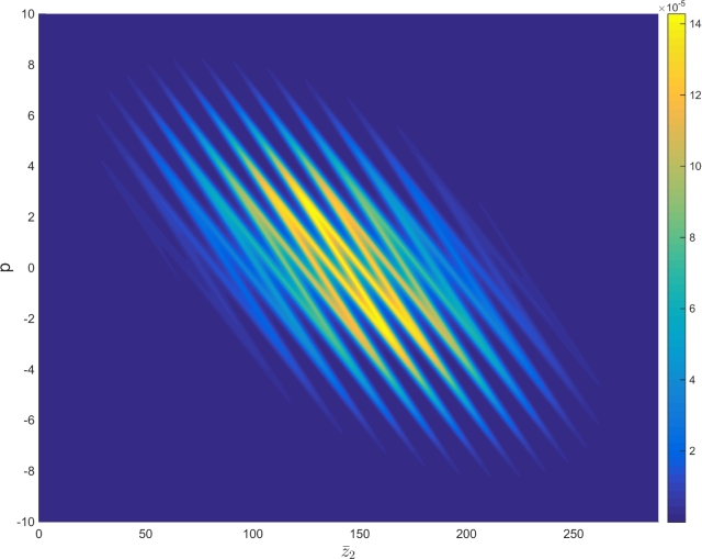
Figure 1 plots the scaled longitudinal phase space distribution function of the electrons after the modulation-dispersive section and before injection into the FEL undulator using the scaled energy parameter with the following parameters: , , , , (or ), , and . The modulation and dispersion of the beam is seen to create a stacked structure of energy chirped ‘beamlets’, slice sections of which are seen to have an energy spread which is reduced from the initial un-transformed beam with . Under certain conditions, each beamlet may then emit and amplify radiation independently of the other beamlets. The combined output from each of the beamlets may then give improved radiation output over the un-transformed beam.
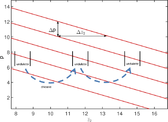
To illustrate how the method functions in the FEL undulator, a simplified version of the beamlet phase space is shown in figure 2, which consists of a series of chirped, zero energy spread, electron beamlets of different mean energies stacked in phase space. The chirp causes the radiation from one section of the chirped beam to drift out of resonance as it propagates into electrons which are resonant at a different wavelength. This impedes the FEL gain process. This effect may be successfully counteracted by using an appropriate undulator tapering to maintain the electron-radiation resonance [22]. (These results have been reproduced using the simulation methods used here and are in very good agreement [23].) Here, a different approach is demonstrated using a periodic series of undulator-chicane modules with multiple beamlets. The beamlets are periodically delayed by the chicanes so as to maintain a resonant interaction with the radiation generated by electrons of the same energy from the other beamlets. (Simulations using this method on the simple beamlet structure of figure 2 have been performed and presented elsewhere [23].) In the electron beam frame therefore, the radiation is passed from beamlet to beamlet so that it always interacts with electrons of a similar energy so maintaining a resonant interaction and giving an improved FEL interaction. This is achieved by making the slippage of a radiation wavefront through the electrons in each undulator-chicane module equal to the spatial separation of the beamlets. The enhanced slippage can also be expected to result in the generation of a series of modes in the radiation spectrum similar to that of [16] which demonstrated that an undulator-chicane lattice will amplify side-band radiation modes that are separated by:
| (8) |
where is the slippage length in scaled units of in one undulator-chicane module [16].
The FEL parameter , where is the electron pulse peak current, and is a measure of FEL efficiency. When considering individual beamlets a FEL parameter may also be defined for each beamlet: where is localised (slice) current of the beamlet. (Note that as the beamlet energy is chirped, the mean pulse energy , is used in the definition of .) Other beamlet parameters are also defined as and a beamlet scaled slice energy . For a beamlet to lase independently its slice energy spread must then satisfy:
| (9) |
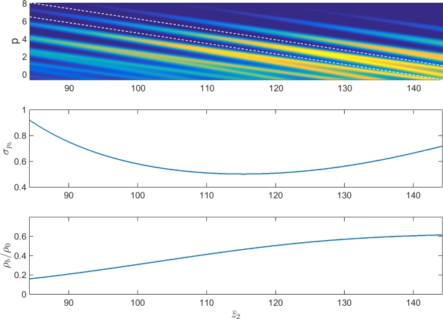
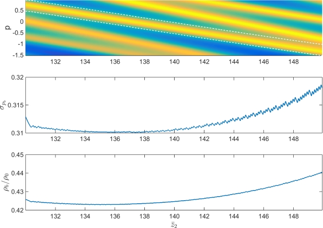
(Note here, that the mean pulse energy is used in the definition of rather than a local ‘slice’ value . This can be considered a reasonable approximation for the inequality (9), so long as does not differ significantly from .) The beamlet slice energy spread and instantaneous fractional FEL parameter , where is the FEL parameter of the un-transformed beam, can be calculated and are shown in figures 3 and 4 towards the higher energy and mid-sections of the electron pulse respectively.
The energy spread condition for FEL lasing of equation (9) may be used with the FEL radiation bandwidth saturation [24] to define the minimum energy separation of the beamlets so that the gain bandwidths of each beamlet do not overlap:
| (10) |
At the centre of the electron pulse the beamlets split into pairs [25], i.e. two per half modulation period, while for the electron pulse higher and lower energies, formed by the modulation extrema, the beamlet pairs merge into single beamlets as seen in figures 3 and 4.
Both the energy spread condition (9) and beamlet separation condition (10) are seen in figure 3 to be satisfied for the higher energy regions of the beamlets. (These conditions are also satisfied at the lower energy regions of the beamlets, but are not shown.) However, the condition placed on the beamlets’ energy separation (10) is not always satisfied at the pulse centre where the beamlets are formed in pairs, as seen in figure 4. Hence, the undulator-chicane slippage length is set equal to the beamlet separation for the higher and lower energy regions of the pulse where the energy separation of the beamlets is approximately a constant.
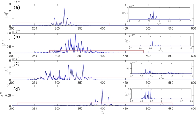
Results of a FEL interaction using an un-transformed (no beamlets) pulse with large energy spread and of the transformed (beamlet) pulse are shown in figure 5. As expected, for the pulse without beamlets and the large energy spread, only small scaled peak powers of are observed in the simulation. However, for the transformed pulse with beamlets that have smaller energy spread, , and that are matched to the undulator-chicane modules, powers 2-3 orders of magnitude greater are observed. For the modulation period of used here (), matching was achieved using undulator modules of periods and isochronous chicane slippages of . It is seen that the FEL lasing is greater for the lower energy beamlets of the pulse around . This preferential FEL interaction and amplification of the lower frequency is consistent with the scaling of the FEL parameter which gives greater values and so strength of interaction, for lower beam energies. In the simulations here, the gain length of the higher to lower energy beamlets is up to 50% larger. Evidence of the modal structure in the spectrum is also observed in the scaled power spectrum (inset), consistent with the undulator-chicane system which from (8) gives a mode spacing of .
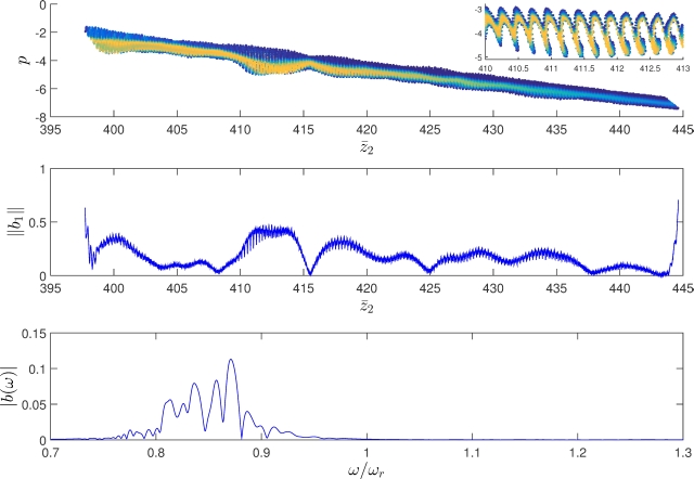
Significant bunching of the electrons in one of the lower energy beamlets, with a mean value of scaled energy , is also observed as shown in figure 6. Note from the lower plot for the spectrum that the electrons are bunched at a lower frequency than the mean resonant frequency of the electron pulse. This frequency shift from resonance is consistent with the lower mean energy of the electrons as and is in agreement with the radiation frequency spectrum of figure 5.
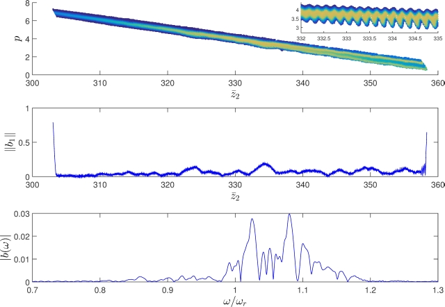
Electron bunching is also observed in a higher energy beamlet of mean scaled energy , shown in figure 7. Here, the bunching is seen to be at a less advanced stage, but can be expected to reach saturation on further propagation through the undulater-chicane lattice.
3 Fourier Synthesised Electron Beams
Further types of phase-space transformation of an electron pulse prior to generating radiation have been proposed and called ‘beam-by-design’ [7]. An example is investigated here to demonstrate the potential of such beam transformation prior to injection into the FEL and the subsequent transformation in the FEL emission stage using a series of undulator-chicane modules. An electron pulse consisting of a series rectangular shaped distributions in phase-space can be generated [13] and contains a periodic series of current ‘spikes’. These current spikes are a source of coherent spontaneous emission which may, through a series of periodic superpositions enabled by chicanes, generate significant radiation output from an undulator-chicane lattice. We note that other methods can generate similar beam structures, e.g. the E-SASE approach [26], however the methods of [13] are used here to demonstrate the types of more exotic interaction that may be modelled using non-averaged simulation codes such as PUFFIN.
3.1 The Model - Coherent Emission from Rectangular Electron Pulses
A new approach to produce so-called ‘RF-function’ electron beams was introduced in [13]. An RF-function generator produces a series of repeated wave forms by combining sine-waves of different frequencies as in a Fourier series. In a similar fashion, an electron pulse can be created with a phase-space that consists of repeated ‘waveforms’ by modulation the electron beam using a series of seeded undulator modulators using different seed wavelengths, amplitudes and phases. Following the notation of [13], here a rectangular beam shape in phase space using a triple modulator-chicane lattice is synthesized and subsequent radiation generation following injection into an undulator chicane-lattice is modelled using PUFFIN.
While in [13] an infinity long electron beam was assumed, here, a finite electron pulse with an initial Gaussian distribution in both and is assumed, as given by equation (6). As detailed in the Appendix, the same Fourier synthesis as outlined in [13] is applied using the beam modulation transforms given by equation (4) and the energy dispersion transforms of equation (5).
In electron phase-space, the vertical segments of the rectangular waveform generate regions of enhanced current, albeit with a larger energy spread. Each period therefore contains two current ‘spikes’ which can generate significant coherent spontaneous emission when their width is of a similar scale to a resonant wavelength [17]. However, due to electron beam dispersion in the undulator, the sharpness of the current spikes reduce on propagation, resulting in diminishing coherent emission. This dispersion of the current spikes may be compensated for by the use of chicane systems with a negative dispersion to allow for more prolonged coherent emission. The design of chicane delay systems with negative dispersion have been previously designed and tested as part of an accelerator lattice [27] and are also necessary for generating the RF-function beam shapes [7, 13]. If the slippage per undulator-chicane module is also made equal to the current spike separation, then the radiation is propagated from spike to spike and, if correctly phased, can facilitate the constructive interference of the coherent emission from each current spike in each new undulator module.
3.2 Results - Coherent Emission from Rectangular Electron Pulses
The following simulations use the same electron pulse parameters as the previous section, i.e., the electron pulse’s large energy spread is prohibitive to FEL gain. The phase-space distribution of the electron beam for the rectangular waveform was constructed from the analysis of the Appendix for three undulator-chicane modules using the following parameters in : ; ; , with , and .
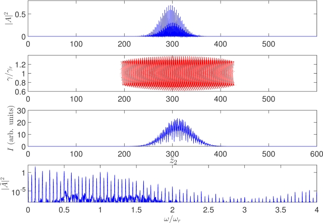
The initial current profile of the electron pulse contains a series of current spikes at half the modulation period corresponding to resonant radiation wavelengths or in units of . On injection into an undulator, these spikes act as a periodic series of phase correlated coherent emitters which, for a relatively short interaction length of , generate a broad modal radiation spectrum as seen figure 8. However, it is seen that alternate current spikes have dispersed to leave a series of more prominent current spikes at twice the initial spacing of .
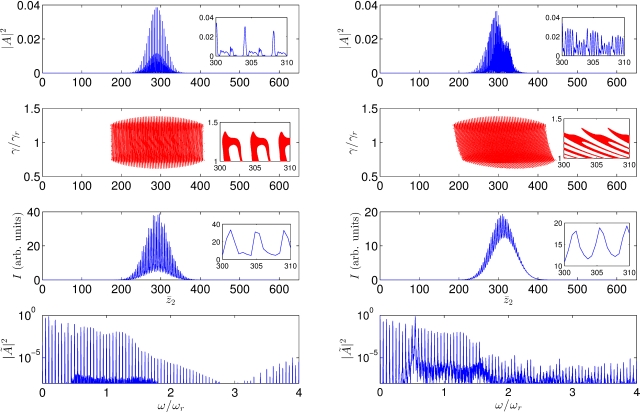
This is reflected in the temporal separation of the larger radiation spikes separated by ). This also agrees with to the spectrum in which a series of modes are generated with separation, from equation (8), of about the resonant frequency.
On propagating further through the interaction region to larger values of , the right hand panels of figure 8 show that the energy modulation of the rectangular electron beam causes the electron beam to disperse in the undulator degrading the visibility of the current spikes and so decreasing the coherent spontaneous emission generated. Clearly, these dispersive effects mean that there is no benefit in increasing the interaction length over that of .
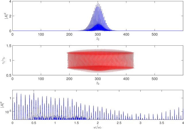
By using chicanes with a negative dispersion it is possible to partially compensate for the undulator dispersion and maintain a spiked current profile that can continue to emit CSE over a larger number of modules. An example of this is shown in figure 9 were the chicane dispersion is set equal the negative of the undulator dispersion, i.e. [23]. The total undulator-chicane slippage for the radiation was again set equal to the current-spike separation, . For this case, undulator-chicane modules of 5 undulator periods and 5 chicane slippage periods were used. In this way, the CSE from successive undulator-chicane modules superimpose and constructively interfere increasing the radiation power emitted.
However, the radiation fields from each undulator-chicane do not superimpose coherently and the radiation energy is seen (not shown) to scale approximately as the number of undulator-chicane modules - a phase-matched coherent superposition would give a radiation energy which scales as the square of the number of undulator-chicane modules. The reason for this non-coherent superposition is that the dispersion of the large energy modulated beam in the undulators cannot be perfectly compensated for by the negative dispersion in the chicanes. (Phase space dispersion of electrons in the undulator is due to differences in the axial speed , while electron dispersion in the chicanes is due to differences in the electron energy, .) This is observed from the slight ‘bowing’ of the rectangular structure of the electrons in phase space in figure 9. Two possible methods to improve this are to reduce the initial energy modulation of the rectangular wave (the results here are for a relatively large energy modulation) or to use a (hypothetical) optimised chicane design which has a non-linear dispersive strength as a function of . Here the latter is used and the results shown in figure 10. Now, the bowing of the rectangular structure of the electrons in phase space is seen to be removed and the power of the radiation increased. The coherent radiation from each undulator-chicane module is now phase matched and is superimposing coherently after each module. The radiation energy is now also observed to increase in proportion to the square of the number of modules.
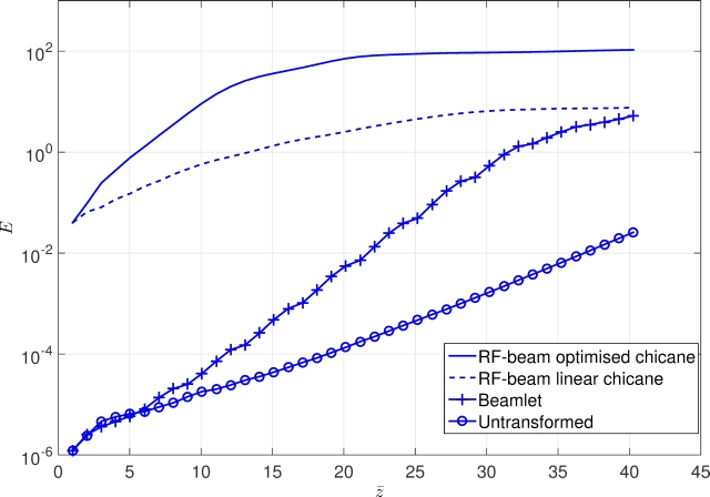
A comparison of a normal (untransformed beam) FEL amplifier with the methods of beamlets of the previous Section and that of the fourier synthesised rectangular beam of this section is given in figure 11 which plots how the scaled energy of the radiation pulses evolves with the interaction length , where:
| (11) |
Before performing the integral in (11) the field was first fourier bandpass filtered so that only contributions about resonance in the interval are considered (this removes the significant low-frequency CSE content.) The introduction of the phase=space transform to generate electron beamlets is seen to increase the exponential growth rate over the normal FEL interaction by a factor of approximately two. While the rectangular electron beams are seen not to have an exponential gain, it is essentially a Coherent Spontaneous Emission process, the starting powers are much greater than the FEL processes which start from spontaneous shot noise. It should be noted that when the CSE simulations predict radiation powers that are a significant fraction of the electron beam energy, that the effects of photon recoil should be included in the model. These effects are not included in the classical simulations presented here.
4 Conclusion
This paper has sought to demonstrate what may be possible when electron beams are transformed to alter their properties before injection into an FEL-type system. It is stressed that the methods demonstrated here are not proposals for any specific design or operational wavelength. Rather, they are used to demonstrate possible research directions towards future light sources, some of which have already been envisaged [7].
Here, the focus was to generate significant radiation output from electron beams that have insufficient beam quality to lase under normal FEL operation. These methods may be developed further and made more specific e.g. to the electron beams generated from plasma accelerator sources which, to date, tend to have relatively high energy spreads. Other possibilities, such as multiple frequency generation, ultra-short pulses, chirped pulses (possibly shorter wavelengths) and others, are potential research areas. One topic that is apparent, but has not been explored here, is the introduction of tapered undulators into the design process. For example, the introduction of tapered undulators, matched to compensate for the chirped beamlets of above, instead of using chicanes, can be expected to produce interesting radiation output.
It is noted that the simulations presented here cannot be modelled effectively, or at all, using simulation codes that are used to successfully model the ‘normal’ types of FEL interactions. Unaveraged FEL codes, such as the PUFFIN code used here, are required.
Appendix
The final distribution function of a triple-modulator-chicane scheme is given below.
The energy modulation parameters , modulation frequencies and modulation phases are associated with first, second and third modulator sections respectively. Similarly are the dispersion factors for chicane 1,2 and 3. is the standard deviations in and . The resonant energy is defined as and the electron pulse centre is given by .
References
References
- [1] Vinko S M et al 2012 Nature 482 59
- [2] Barends R M T et al 2014 Nature 505 244
- [3] Edwards G S et al 2003 Rev. Sci. Instrum. 74 3207
- [4] Emma P et al 2010 Nat. Photonics 4 641
- [5] Ishikawa T et al 2012 Nat. Photonics 6 540
- [6] McNeil B W J and Thompson N R 2010 Nat. Photonics 4 814
- [7] Hemsing E, Stupakov G, and Xiang D 2014 Rev. Mod. Phys. 86 897
- [8] Campbell L T, McNeil B W J and Reiche S 2014 New J. Phys. 16 103019
- [9] Couprie M E, Loulergue A, Labat M, Lehe R, and Malka V 2014 J. Phys. B: At. Mol. Opt. Phys. 47 234001
- [10] Nakajima K 2014 High Power Laser Science and Engineering / Volume 2 / December 2014 / e31
- [11] Maier A R et al 2012 Phys. Rev. X 2 031019
- [12] Huang Z, Ding Y, and Schroeder C B 2012 Phys. Rev. Lett. 109 204801
- [13] Hemsing E and Xiang D 2013 Phys. Rev. ST-Accel. Beams 16 010706
- [14] Campbell L T and McNeil B W J 2012 Physics of Plasmas 19 093119
- [15] Ronsivalle C et al. 2014 New J. Phys. 16 033018
- [16] Thomson NR and McNeil BWJ 2008 Phys. Rev. Lett. 100 203901
- [17] McNeil B W J, Robb G R M, and Jaroszynski D A 2000 Nuclear Instruments and Methods in Physics Research A 445 72
- [18] Bonifacio R, Pellegrini C and Narducci L M 1984 Opt. Comm. 50 373
- [19] Xiang D and Stupakov G 2009 Phys. Rev. ST-Accel. Beams 12 030702
- [20] Bonifacio R, McNeil B W J and Pierini P 1989 Phys. Rev. A 40 4467
- [21] McNeil B W J, Poole M W and Robb G R M 2003 Phys. Rev. ST-Accel. Beams 6 070701
- [22] Saldin E, Schneidmiller E, and Yurkov M 2006 Phys. Rev. ST-Accel. Beams 9, 050702
- [23] Henderson J R, Campbell L T and McNeil B W J 2014 Proceedings of FEL2014, Basel, Switzerland MOC04 303
- [24] Bonifacio R, De Salvo L, Pierini P, Piovella N and Pellegrini C 1994 Phys. Rev. Lett. 73 70
- [25] Henderson J R and McNeil B W J, 2012 EPL 100 64001
- [26] Zholents A A 2005 Phys. Rev. ST-AB 8 040701
- [27] Jackson F, Angal-Kalinin D, Jones J K, and Williams P H 2013 4th International Particle Accelerator Conference (IPAC13) Shanghai, China WEPWA063 2262