79
Synthesis of “correct” adaptors for protocol enhancement in component-based systems
Abstract
Adaptation of software components is an important issue in Component Based Software Engineering (CBSE). Building a system from reusable or Commercial-Off-The-Shelf (COTS) components introduces a set of problems, mainly related to compatibility and communication aspects. On one hand, components may have incompatible interaction behavior. This might require to restrict the system’s behavior to a subset of safe behaviors. On the other hand, it might be necessary to enhance the current communication protocol. This might require to augment the system’s behavior to introduce more sophisticated interactions among components. We address these problems by enhancing our architectural approach which allows for detection and recovery of incompatible interactions by synthesizing a suitable coordinator. Taking into account the specification of the system to be assembled and the specification of the protocol enhancements, our tool (called SYNTHESIS) automatically derives, in a compositional way, the glue code for the set of components. The synthesized glue code implements a software coordinator which avoids incompatible interactions and provides a protocol-enhanced version of the composed system. By using an assume-guarantee technique, we are able to check, in a compositional way, if the protocol enhancement is consistent with respect to the restrictions applied to assure the specified safe behaviors.
1 Introduction
Adaptation of software components is an important issue in Component Based Software Engineering (CBSE). Nowadays, a growing number of systems are built as composition of reusable or Commercial-Off-The-Shelf (COTS) components. Building a system from reusable or from COTS [14] components introduces a set of problems, mainly related to communication and compatibility aspects. Often, components may have incompatible interaction behavior. This might require to restrict the system’s behavior to a subset of safe behaviors. For example, restrict to the subset of deadlock-free behaviors or, in general, to a specified subset of desired behaviors. Moreover, it might be necessary to enhance the current communication protocol. This requires augmenting the system’s behavior to introduce more sophisticated interactions among components. These enhancements (i.e.: protocol transformations) might be needed to achieve dependability, to add extra-functionality and/or to properly deal with system’s architecture updates (i.e.: components aggregating, inserting, replacing and removing).
We address these problems enhancing our architectural approach which
allows for detection and recovery of incompatible interactions by
synthesizing a suitable coordinator [4, 9, 11].
This coordinator represents a initial glue code. So far, as reported
in [4, 9, 11], the approach only focussed on
the restriction of the system’s behavior to a subset of safe (i.e.:
desired) behaviors. In this paper, we propose an extension that
makes the coordinator synthesis approach also able to automatically
transform the coordinator’s protocol by enhancing the initial glue
code. We implemented the whole approach in our SYNTHESIS
tool [9, 15]
(http://www.di.univaq.it/tivoli/SYNTHESIS/synthesis.html).
In [15], which is a companion paper, we also apply
SYNTHESIS to a real-scale context. Since in this paper we are
focusing only on the formalization of the approach, in
Section 5, we will simply refer to an
explanatory example and we will omit implementation details which
are completely described in [15].
Starting from the specification of the system to be assembled and from the specification of the desired behaviors, SYNTHESIS automatically derives the initial glue code for the set of components. This initial glue code is implemented as a coordinator mediating the interaction among components by enforcing each desired behavior as reported in [4, 9, 11]. Subsequently, taking into account the specification of the needed protocol enhancements and performing the extension we formalize in this paper, SYNTHESIS automatically derives, in a compositional way, the enhanced glue code for the set of components. This last step represents the contribution of this paper with respect to [4, 9, 11]. The enhanced glue code implements a software coordinator which avoids not only incompatible interactions but also provides a protocol-enhanced version of the composed system. More precisely, this enhanced coordinator is the composition of a set of new coordinators and components assembled with the initial coordinator in order to enhance its protocol. Each new component represents a wrapper component. A wrapper intercepts the interactions corresponding to the initial coordinator’s protocol in order to apply the specified enhancements without modifying 111This is needed to achieve compose-ability in both specifying the enhancements and implementing them. the initial coordinator and the components in the system. The new coordinators are needed to assemble the wrappers with the initial coordinator and the rest of the components forming the composed system. It is worthwhile noticing that, in this way, we are readily compose-able; we can treat the enhanced coordinator as a new composite initial coordinator and enforce new desired behaviors as well as apply new enhancements. This allows us to perform a protocol transformation as composition of other protocol transformations by improving on the reusability of the synthesized glue code.
When we apply the specified protocol enhancements to produce the enhanced coordinator, we might re-introduce incompatible interactions avoided by the initial coordinator. That is, the enhancements do not hold the desired behaviors specified to produce the initial coordinator. In this paper, we also show how to check if the protocol enhancement holds the desired behaviors enforced through the initial coordinator. This is done, in a compositional way, by using an assume-guarantee technique [6].
The paper is organized as follows: Section 2 discusses related work. Section 3 introduces background notions helpful to understand our approach. Section 4 illustrates the technique concerning the enhanced coordinator synthesis. Section 5 formalizes the coordinator synthesis approach for protocol enhancement in component-based systems, and uses a simple explanatory example to illustrate the ideas. Section 6 formalizes the technique used to check the consistency of the applied enhancements with respect to the enforced desired behaviors. Section 7 discusses future work and concludes.
2 Related work
The approach presented in this paper is related to a number of other approaches that have been considered in the literature. The most closely related work is the scheduler synthesis for discrete event physical systems using supervisory control [2]. In those approaches system’s allowable executions are specified as a set of traces. The role of the supervisory controller is to interact with the running system in order to cause it to conform to the system specification. This is achieved by restricting behavior so that it is contained within the desired behavior. To do this, the system under control is constrained to perform events only in strict synchronization with a synthesized supervisor. The synthesis of a supervisor that restrict behaviors resembles one aspect of our approach defined in Section 4, since we also eliminate certain incompatible behaviors through synchronized coordination. However, our approach goes well beyond simple behavioral restriction, also allowing augmented interactions through protocol enhancements.
Recently a reasoning framework that supports modular checking of behavioral properties has been proposed for the compositional analysis of component-based design [3, 10]. In [3], they use an automata-based approach to capture both input assumptions about the order in which the methods of a component are called, and output guarantees about the order in which the component calls external methods. The formalism supports automatic compatibility checks between interface models, where two components are considered to have compatible interfaces if there exists a legal environment that lets them correctly interact. Each legal environment is an adaptor for the two components. However, they provide only a consistency check among component interfaces, but differently from our work do not treat automatic synthesis of adaptors of component interfaces. In [10], they use a game theoretic approach for checking whether incompatible component interfaces can be made compatible by inserting a converter between them which satisfies specified requirements. This approach is able to automatically synthesize the converter. The idea they develop is the same idea we developed in our precedent works [4, 9, 11]. That is the restriction of the system’s behavior to a subset of safe behaviors. Unlike the work presented in this paper, they are only able to restrict the system’s behavior to a subset of desired behaviors and they are not able to augment the system’s behavior to introduce more sophisticated interactions among components.
Our research is also related to work in the area of protocol adaptor synthesis [18]. The main idea of this approach is to modify the interaction mechanisms that are used to glue components together so that compatibility is achieved. This is done by integrating the interaction protocol into components. However, they are limited to only consider syntactic incompatibilities between the interfaces of components and they do not allow the kind of protocol transformations that our synthesis approach supports.
In other previous work, of one of the authors, we showed how to use formalized protocol transformations to augment connector behavior [13]. The key result was the formalization of a useful set of connector protocol enhancements. Each enhancement is obtained by composing wrappers. This approach characterizes wrappers as modular protocol transformations. The basic idea is to use wrappers to enhance the current connector communication protocol by introducing more sophisticated interactions among components. Informally, a wrapper is new code that is interposed between component interfaces and communication mechanisms. The goal is to alter the behavior of a component with respect to the other components in the system, without actually modifying the component or the infrastructure itself. While this approach deals with the problem of enhancing component interactions, unlike this work it does not provide automatic support for composing wrappers, or for automatically eliminating incompatible interaction behaviors.
3 Background
In this section we discuss the background needed to understand the approach that we formalize in Section 4.
3.1 The reference architectural style
The starting point for our work is the use of a formal architectural model of the system representing the components to be integrated and the connectors over which the components will communicate [12]. To simplify matters we will consider the special case of a generic layered architecture in which components can request services of components below them, and notify components above them. Specifically, we assume each component has a top and bottom interface. The top (bottom) interface of a component is a set of top (bottom) ports. Connectors between components are synchronous communication channels defining top and bottom ports.
Components communicate by passing two types of messages: notifications and requests. A notification is sent downward, while a request is sent upward. We will also distinguish between two kinds of components (i) functional components and (ii) coordinators. Functional components implement the system’s functionality, and are the primary computational constituents of a system (typically implemented as COTS components). Coordinators, on the other hand, simply route messages and each input they receive is strictly followed by a corresponding output. We make this distinction in order to clearly separate components that are responsible for the functional behavior of a system and components that are introduced to aid the integration/communication behavior.
Within this architectural style, we will refer to a system as a Coordinator-Free Architecture (CFA) if it is defined without any coordinators. Conversely, a system in which coordinators appear is termed a Coordinator-Based Architecture (CBA) and is defined as a set of functional components directly connected to one or more coordinators, through connectors, in a synchronous way.

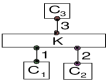
Figure 1 illustrates a CFA (left-hand side) and its corresponding CBA (right-hand side). , and are functional components; is a coordinator. The communication channels identified by , , and are connectors.
3.2 Configuration formalization
To formalize the behavior of a system we use High level Message Sequence Charts (HMSCs) and basic Message Sequence Charts (bMSCs) [5] specification of the composed system. From it, we can derive the corresponding CCS (Calculus of Communicating Systems) processes [8] (and hence Labeled Transitions Systems (LTSs)) by applying a suitable adaptation of the translation algorithm presented in [17]. HMSC and bMSC specifications are useful as input language, since they are commonly used in software development practice. Thus, CCS can be regarded as an internal specification language. Later we will see an example of derivation of LTSs from a bMSCs and HMSCs specification (Section 5.1).
To define the behavior of a composition of components, we simply place in parallel the LTS descriptions of those components, hiding the actions to force synchronization. This gives a CFA for a set of components.
We can also produce a corresponding CBA for these components with equivalent behavior by automatically deriving and interposing a ”no-op” coordinator between communicating components. That coordinator does nothing (at this point), it simply passes events between communicating components (as we will see later the coordinator will play a key role in restricting and augmenting the system’s interaction behavior). The ”no-op” coordinator is automatically derived by performing the algorithm described in [4, 9, 11].
Formally, using CCS we define the CFA and the CBA for a set of components as follows:
Definition 1.
Coordinator
Free Architecture (CFA)
where for all
,
is the action set of the CCS process .
Definition 2.
Coordinator
Based Architecture (CBA)
where for all
, is the action set of the CCS process ,
and are relabelling functions such that
for all ; is
the CSS process corresponding to the automatically synthesized
coordinator.
By referring to [8], is the parallel composition operator and is the restriction operator. There is a finite set of visible actions over which ranges. We denote by the action complement: if , then , while if , then . By we denote a substitution of for in . If , then . Each . By referring to Figure 1, 0 identifies the only connector (i.e: communication channel) present in the CFA version of the composed system. Each relabelling function is needed to ensure that the components no longer synchronize directly. In fact by applying these relabelling functions (i.e.: for all ) each component synchronizes only with the coordinator through the connector (see right-hand side of Figure 1).
3.3 Automatic synthesis of failure-free
coordinators
In this section, we simply recall that from the MSCs specification of the CFA and from a specification of desired behaviors, the old version of SYNTHESIS automatically derives the corresponding deadlock-free CBA which satisfies each desired behavior. This is done by synthesizing a suitable coordinator that we call failure-free coordinator. Informally, first we synthesize a ”no-op” coordinator. Second, we restrict its behavior by avoiding possible deadlocks and enforcing the desired behaviors. Each desired behavior is specified as a Linear-time Temporal Logic (LTL) formula (and hence as the corresponding Büchi Automaton) [6]. Refer to [4, 9, 11] for a formal description of the old approach and for a brief overview on the old version of our SYNTHESIS tool.
4 Method description
In this section, we informally describe the extension of the old coordinator synthesis approach [4, 9, 11] that we formalize in Section 5 and we implemented in the new version of the SYNTHESIS tool. The extension starts with a deadlock-free CBA which satisfies specified desired behaviors and produces the corresponding protocol-enhanced CBA.
The problem we want to face can be informally phrased as follows: let be a set of desired behaviors, given a deadlock-free and -satisfying CBA system for a set of black-box components interacting through a coordinator , and a set of coordinator protocol enhancements , if it is possible, automatically derive the corresponding enhanced, deadlock-free and -satisfying CBA system .
We are assuming a specification of: i) in terms of a description of components and a coordinator as LTSs, ii) in terms of a set of Büchi Automata, and of iii) in form of bMSCs and HMSCs specification. In the following, we discuss our method proceeding in two steps as illustrated in Figure 2.
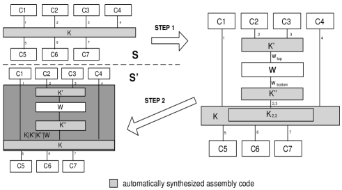
In the first step, by starting from the specification of and , if it is possible, we apply each protocol enhancement in . This is done by inserting a wrapper component between (see Figure 2) and the portion of concerned with the specified protocol enhancements (i.e.: the set of and components of Figure 2). It is worthwhile noticing that we do not need to consider the entire model of but we just consider the ”sub-coordinator” which represents the portion of that communicates with and (i.e.: the ”sub-coordinator” of Figure 2). represents the ”unchangeable”222Since we want to be readily compose-able, our goal is to apply the enhancements without modifying the coordinator and the components. environment that ”offers” to . The wrapper is a component whose interaction behavior is specified in each enhancement of . Depending on the logic it implements, we can either built it by scratch or acquire it as a pre-existent component (e.g. a data translation component). intercepts the messages exchanged between , and and applies the enhancements in on the interactions performed on the communication channels 2 and 3 (i.e.: connectors 2 and 3 of Figure 2). We first decouple (i.e.: ), and to ensure that they no longer synchronize directly. Then we automatically derive a behavioral model of (i.e.: a LTS) from the bMSCs and HMSCs specification of . We do this by exploiting our implementation of the translation algorithm described in [17]. Finally, if the insertion of in allows the resulting composed system (i.e.: after the execution of the second step) to still satisfy each desired behavior in , is interposed between , and . To insert , we automatically synthesize two new coordinators and . In general, always refers to the coordinator between and the components affected by the enhancement. always refers to the coordinator between and . By referring to Section 3.1, to do this, we automatically derive two behavioral models of : i) which is the behavior of only related to its top interface and ii) which is the behavior of only related to its bottom interface.
In the second step, we derive the implementation of the synthesized
glue code used to insert in . This glue code is the actual
code implementing and . By referring
to Figure 2, the parallel composition of
, , and represents the
enhanced coordinator.
By iterating the whole approach, may be treated as with respect to the enforcing of new desired behaviors and the application of new enhancements. This allows us to achieve compose-ability of different coordinator protocol enhancements (i.e.: modular protocol’s transformations). In other words, our approach is compositional in the automatic synthesis of the enhanced glue code.
5 Method formalization
In this section, by using an explanatory example, we formalize the two steps of our method. For the sake of brevity we limit ourselves to formalize the core of the extended approach. Refer to [1] for the formalization of the whole approach.
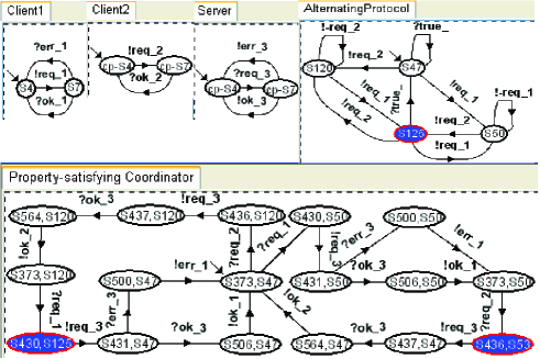
In Figure 3, we consider screen-shots of the
SYNTHESIS tool related to both the specification of and
of . , and are the components in
.
Property-satisfying Coordinator is the coordinator in
which satisfies the desired behavior denoted with
AlternatingProtocol. In this example,
AlternatingProtocol is the only element in the specification
. The CBA configuration of is shown in the right-hand side of
Figure 1 where , , and are
, , and Property-satisfying
Coordinator of Figure 3 respectively.
Each LTS describes the behavior of a component or of a coordinator instance in terms of the messages (seen as I/O actions) exchanged with its environment333The environment of a component/coordinator is the parallel composition of all others components in the system.. Each node is a state of the instance. The node with the incoming arrow (e.g.: the state of in Figure 3) is the starting state. An arc from a node to a node denotes a transition from to . The transition labels prefixed by ”!” denote output actions (i.e.: sent requests and notifications), while the transition labels prefixed by ”?” denote input actions (i.e.: received requests and notifications). In each transition label, the symbol ”_” followed by a number denotes the identifier of the connector on which the action has been performed. The filled nodes on the coordinator’s LTS denote states in which one execution of the behavior specified by the Büchi Automaton AlternatingProtocol has been accomplished.
Each Büchi Automaton (see AlternatingProtocol in Figure 3) describes a desired behavior for . Each node is a state of . The node with the incoming arrow is the initial state. The filled nodes are the states accepting the desired behavior. The syntax and semantics of the transition labels is the same of the LTSs of components and coordinator except two kinds of action: i) a universal action (e.g.: in Figure 3) which represents any possible action444The prefixed symbols ”!” or ”?”, in the label of a universal action, are ignored by SYNTHESIS., and ii) a negative action (e.g.: in Figure 3) which represents any possible action different from the negative action itself555The prefixed symbols ”!” or ”?”, in the label of a negative action, are still interpreted by SYNTHESIS..
performs a request (i.e.: action ) and waits for a erroneous or successful notification: actions and respectively. simply performs the request and it never handles erroneous notifications. receives a request and then it may answer either with a successful or an erroneous notification 666The error could be either due to an upper-bound on the number of request that can accept simultaneously or due to a general transient-fault on the communication channel..
AlternatingProtocol specifies the behavior of that guarantees the evolution of all components. It specifies that and must perform requests by using an alternating coordination protocol. More precisely, if performs an action (the transition from the state to the state in Figure 3) then it cannot perform again (the loop transition on the state in Figure 3) if has not performed (the transition from the state to the accepting state in Figure 3) and viceversa.
In Figure 4.(a), we consider the specification of as given in input to the SYNTHESIS tool. In this example, the RETRY enhancement is the only element in .
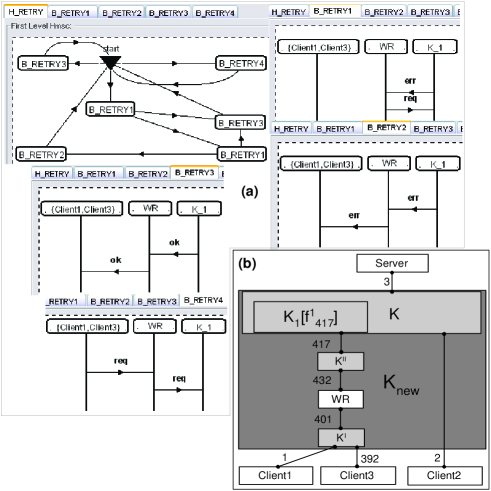
is an interactive client and once an erroneous notification occurs, it shows a dialog window displaying information about the error. The user might not appreciate this error message and he might lose the degree of trust in the system. By recalling that the dependability of a system reflects the user s degree of trust in the system, this example shows a commonly practiced dependability-enhancing technique. The wrapper WR attempts to hide the error to the user by re-sending the request a finite number of times. This is the RETRY enhancement specified in Figure 4.(a). The wrapper WR re-sends at most two times. Moreover, the RETRY enhancement specifies an update of obtained by inserting which is a new client. In specifying enhancements, we use ”augmented”-bMSCs. By referring to [5], each usual bMSC represents a possible execution scenario of the system. Each execution scenario is described in terms of a set of interacting components, sequences of method call and possible corresponding return values. To each vertical lines is associated an instance of a component. Each horizontal arrow represents a method call or a return value. Each usual HMSC describes possible continuations from a scenario to another one. It is a graph with two special nodes: the starting and the ending node. Each other node is related to a specified scenario. An arrow represents a transition from a scenario to another one. In other words, each HMSC composes the possible execution scenarios of the system. The only difference between ”augmented”-bMSCs and usual bMSCs is that to each vertical line can be associated a set of component instances (e.g.: in Figure 4.(a)) rather than only one instance. This is helpful when we need to group components having the same interaction behavior.
5.1 First step: wrapper insertion procedure
By referring to Section 4, each enhancement MSCs specification (see Figure 4.(a)) is in general described in terms of the sub-coordinator (i.e.: in Figure 4.(a)), the wrapper (WR), the components in () and the new components (). The LTS of the sub-coordinator is automatically derived from the LTS of the coordinator in () by performing the following algorithm:
Definition 3.
construction algorithm
Let be the
LTS for a component (or a coordinator) , we derive the LTS
, , of the behavior of on channels
j,..,j+h as follows:
-
1.
set equal to ;
-
2.
for each loop of labeled with an action where do:
remove from the set of arcs of ; -
3.
for each arc of labeled with an action where do:
-
•
remove from the set of arcs of ;
-
•
if is the starting state then
set as the starting state; -
•
for each other arc of do:
replace with ; -
•
for each arc of do:
replace with ; -
•
for each arc of with do:
replace with ; -
•
for each arc of with do:
replace with ; -
•
for each loop of do:
replace with ; -
•
remove from the set of nodes of ;
-
•
-
4.
until is a non-deterministic LTS (i.e.: it contains arcs labeled with the same action and outgoing the same node) do:
-
•
for each pair of loops and of labeled with the same action do:
remove from the set of arcs of ; -
•
for each pair of arcs and of labeled with the same action do:
remove from the set of arcs of ; -
•
for each pair of arcs ( and ) or ( and ) of labeled with the same action do:
-
–
remove from the set of arcs of ;
-
–
if is the starting state then
set as the starting state; -
–
for each ingoing arc in , outgoing arc from and loop on do:
move the extremity on of , and
on ; -
–
remove from the set of nodes of .
-
–
-
•
Informally, the algorithm of Definition 3 ”collapses” (steps 1,2 and 3) linear and/or cyclic paths made only of actions on channels . Moreover, it also avoids (step 4) possible ”redundant” non-deterministic behaviors777These behaviors might be a side effect due to the collapsing..
By referring to Figure 5, the LTS of is the Restricted Coord.
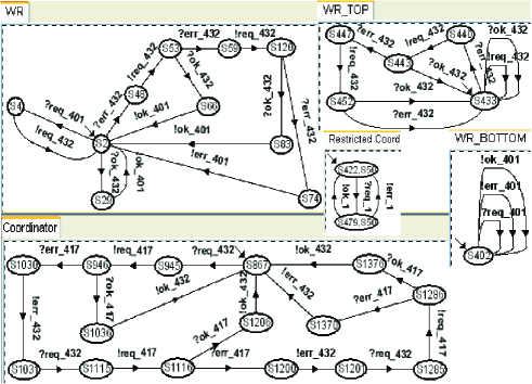
In general, once we derived , we decouple from the components (i.e.: ) connected through the connectors which are related to the specified enhancement (i.e.: the connector 1). To do this, we use the decoupling function defined as follows:
Definition 4.
Decoupling function
Let be the set of action labels of the coordinator ,
let be a subset of all connectors
identifiers888By referring to
Section 5, the connectors identifiers are
postfixed to the labels in . of and let be
a new connector identifier, we define the
”decoupling” function as follows:
-
•
, if then:
The unique connector identifier is automatically generated by SYNTHESIS. In this way we ensure that and no longer synchronize directly. In [15], we detail the correspondence between the decoupling function and components/coordinator deployment.
Now, by continuing the method described in
Section 4, we derive the LTSs for the wrapper
(see WR in Figure 5) and the new components
(the of is equal to the LTS of in
Figure 3 except for the connector identifier). We
recall that SYNTHESIS does that by taking into account the
enhancements specification and by performing its implementation of
the translation algorithm described in [17]. It
is worthwhile noticing that SYNTHESIS automatically generates
the connector identifiers for the actions performed by WR and
. By referring to Section 3.1, WR
is connected to its environment through two connectors: i) one on
its top interface (i.e.: the connector in
Figure 4.(b)) and ii) one on its bottom interface
(i.e.: the connector in Figure 4.(b)). Finally,
as we will see in detail in Section 6, if the insertion of
WR allows the resulting composed system to still satisfy
AlternatingProtocol, WR is interposed between
, and . We recall that
is (see Restricted Coord in
Figure 5) renamed after the decoupling. To insert
WR, SYNTHESIS automatically synthesizes two new
coordinators and . Coordinator
in Figure 5 is the LTS for . For
the purposes of this paper, in Figure 5, we omit
the LTS for . is derived by taking
into account both the LTSs of and
WR_TOP (see Figure 5) and by performing
the old synthesis approach [4, 9, 11]. While
is derived analogously to the LTSs of ,
and WR_BOTTOM (see Figure 5).
The LTSs of WR_TOP and WR_BOTTOM are
WR432 and WR401 respectively. By referring
to Definition 3, WR432 and
WR401 model the behavior of WR on channels 432
and 401 respectively. The resulting enhanced, deadlock-free and
Alternating Protocol-satisfying system is
where
(see Figure 4.(b)).
In [1], we proved the correctness and completeness of
the approach.
5.2 Second step: synthesis of the glue code implementation
The parallel composition represents the model of the enhanced coordinator. By referring to Section 4, we recall that K is the initial glue code for and WR is a COTS component whose interaction behavior is specified by the enhancements specification . That is, the actual code for WR and is already available. Thus, in order to derive the code implementing , SYNTHESIS automatically derives the actual code implementing and . Using the same technique described in [4, 9, 11, 15], this is done by exploiting the information stored in the nodes and arcs of the LTSs for and . More precisely, the code implementing and reflects the structure of their LTSs which describe state machines. For the sake of brevity, here, we omit a detailed description of the code synthesis. Refer to [4, 9, 11, 15] for it. In [9, 15], we validated and applied SYNTHESIS for assembling Microsoft COM/DCOM components. The reference development platform of the current version of SYNTHESIS is Microsoft Visual Studio 7.0 with Active Template Library.
6 Checking enhancement
consistency
In this section we formalize a compositional technique to check if the applied enhancements are consistent with respect to the previously enforced desired behaviors. In other words, given the Büchi Automata specification of a desired behavior , given the deadlock-free and -satisfying coordinator and given the MSCs specification of an enhancement , we check (in a compositional way) if the enhanced coordinator still satisfies ( ).
In general, we have to check . By exploiting the constraints of our architectural style, it is enough to check where is the set of channel identifiers which are both channels in and in the set of channel identifiers for the action labels in . In order to avoid the state explosion phenomenon we should decompose the verification without composing in parallel the processes and . We do that by exploiting the assume-guarantee paradigm for compositional reasoning [6].
By recasting the typical proof strategy of the
assume-guarantee paradigm in our context, we know that if
and
hold then we can conclude that
is true. This proof strategy can also be expressed as
the following inference rule:
where is a LTL formula (and hence it is modeled as a Büchi Automaton). We recall that, in , already satisfies . Once we applied to obtain the enhanced system , represents the assumptions (in ) on the environment of that must be held on the channel in order to make able to still satisfy . Without loss of generality, let be where is the set of channel identifiers for the action labels in ; then is the Büchi Automaton corresponding to where and . For the example illustrated in Section 5, and are the Büchi Automata corresponding to (i.e.: showed in Figure 6) and to ( showed in Figure 6) respectively.
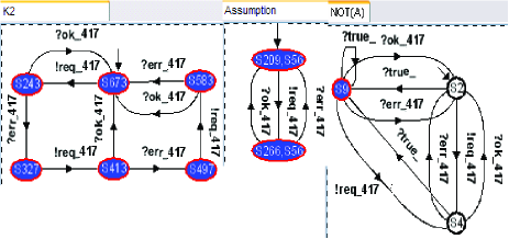
In general, a formula means . While a formula means if holds then . In our context, is modeled as the corresponding Büchi Automaton . is modeled as the corresponding LTS. By referring to [6], to a LTS always corresponds a Büchi Automaton . With we denote the language accepted by . Exploiting the usual automata-based model checking approach [6], to check if we first automatically build the product language and then we check if is empty.
Theorem 1.
Enhancement consistency check
Let be the Büchi Automata specification of a desired
behavior for a system formed by components; let
be the deadlock-free and -satisfying coordinator for the
components in ; let be the MSCs specification of a
-protocol enhancement; let be the adaptor
between and the wrapper implementing the enhancement ; let
the identifier of the channel connecting
with ; let the set of channel identifiers which
are both channels in the set of channel identifiers for the action
labels in and in the set of channels identifiers affected by
the enhancement ; and let be a relabeling function in
such a way that and
for all , if
then
and hence is consistent with respect to .
Proof.
Let be the Büchi Automaton corresponding to , if then . That is, holds. Moreover, by construction of , holds too. By applying the inference rule of the assume-guarantee paradigm, is true and hence . ∎
By referring to Theorem 1, to check if is
consistent with respect to , it is enough to check if holds. In
other words, it is enough to check if provides
with the environment it expects (to still satisfy ) on the
channel connecting to (i.e.: the connector
identified by ). In the example illustrated in
Section 5, RETRY is consistent with
respect to AlternatingProtocol. In fact, by referring to
Figure 6, is the Büchi Automaton for
(i.e.: for
of Theorem 1) and is the Büchi Automaton for
(i.e.: for of
Theorem 1). By automatically building the product
language between the languages accepted by and ,
SYNTHESIS concludes that and hence that
AlternatingProtocol.
That is RETRY is consistent with respect to
AlternatingProtocol.
7 Conclusion and future work
In this paper, we combined the approaches of protocol transformation formalization [13] and of automatic coordinator synthesis [4, 9, 11] to produce a new technique for automatically synthesizing failure-free coordinators for protocol enhanced in component-based systems. The two approaches take advantage of each other: while the approach of protocol transformations formalization adds compose-ability to the automatic coordinator synthesis approach, the latter adds automation to the former. This paper is a revisited and extended version of [7]. With respect to [7], the novel aspects of this work are that we have definitively fixed and extended the formalization of the approach, we have implemented it in our ”SYNTHESIS” tool and we have formalized and implemented the enhancement consistency check.
The key results are: (i) the extended approach is compositional in the automatic synthesis of the enhanced coordinator; that is, each wrapper represents a modular protocol transformation so that we can apply coordinator protocol enhancements in an incremental way by re-using the code synthesized for already applied enhancements; (ii) we are able to add extra functionality to a coordinator beyond simply restricting its behavior;(iii) this, in turn, allows us to enhance a coordinator with respect to a useful set of protocol transformations such as the set of transformations referred in [13]. The automation and applicability of both the old (presented in [4, 9, 11]) and the extended (presented in this paper and in [15]) approach for synthesizing coordinators is supported by our tool called ”SYNTHESIS” [9, 15].
As future work, we plan to: (i) develop more user-friendly specification of both the desired behaviors and the protocol enhancements (e.g., UML2 Interaction Overview Diagrams and Sequence Diagrams); (ii) validate the applicability of the whole approach to large-scale examples different than the case-study treated in [15] which represents the first attempt to apply the extended version of ”SYNTHESIS” (formalized in this paper) in real-scale contexts.
References
- [1] M. Autili. Sintesi automatica di connettori per protocolli di comunicazione evoluti. Tesi di laurea in Informatica, Universitá dell’Aquila - April,2004 - http://www.di.univaq.it/tivoli/AutiliThesis.pdf.
- [2] S. Balemi, G. J. Hoffmann, P. Gyugyi, H. Wong-Toi, and G. F. Franklin. Supervisory control of a rapid thermal multiprocessor. IEEE Transactions on Automatic Control, 38(7):1040–1059, July 1993.
- [3] L. de Alfaro and T. Heinzinger. Interface automata. In ACM Proc. of the joint 8th ESEC and 9th FSE, 2001.
- [4] P. Inverardi and M. Tivoli. Software Architecture for Correct Components Assembly - Chapter in: Formal Methods for the Design of Computer, Communication and Software Systems: Software Architecture. Springer, LNCS 2804, Sept. 2003.
- [5] ITU-T. Reccomendation z.120. message sequence charts. (msc’96), 1996.
- [6] E. M. C. Jr., O. Grumberg, and D. A. Peled. Model Checking. The MIT Press, 2001.
- [7] M.Autili, P.Inverardi, and M.Tivoli. Automatic adaptor synthesis for protocol transformation. In WCAT04, 2004.
- [8] R. Milner. Communication and Concurrency. Prentice Hall, New York, 1989.
- [9] M.Tivoli, P.Inverardi, V.Presutti, A.Forghieri, and M.Sebastianis. Correct components assembly for a product data management cooperative system. In proceedings of the Int. Symposium CBSE7. May,2004. Springer, LNCS 3054, 2007.
- [10] R. Passerone, L. de Alfaro, T. Heinzinger, and A. L. Sangiovanni-Vincentelli. Convertibility verification and converter synthesis: Two faces of the same coin. In Proc. of ICCAD, 2002.
- [11] P.Inverardi and M.Tivoli. Failure-free connector synthesis for correct components assembly. In Proceedings of SAVCBS’03, 2003.
- [12] M. Shaw and D. Garlan. Software Architecture: Perspectives on an Emerging Discipline. Prentice Hall, 1996.
- [13] B. Spitznagel and D. Garlan. A compositional formalization of connector wrappers. In proceeding of the 25th ICSE’03 - Portland, OG (USA), May 2003.
- [14] C. Szyperski. Component Software. Beyond Object Oriented Programming. Addison Wesley, 1998.
- [15] M. Tivoli, M. Autili, and P. Inverardi. Synthesis: a tool for synthesizing correct and protocol-enhanced adaptors. submitted for publication - Aug,2004 - http://www.di.univaq.it/tivoli/LastSynthesis.pdf.
- [16] M. Tivoli and D. Garlan. Coordinator synthesis for reliability enhancement in component-based systems. Carnegie Mellon University, C.S.Dep. - Tech.Rep. - http://www.di.univaq.it/tivoli/CMUtechrep.pdf.
- [17] S. Uchitel, J. Kramer, and J. Magee. Detecting implied scenarios in message sequence chart specifications. In ACM Proceedings of the joint 8th ESEC and 9th FSE, Vienna, Sep 2001.
- [18] D. M. Yellin and R. E. Strom. Protocol specifications and component adaptors. ACM Transactions on Programming Languages and Systems, 19(2):292–333, march 1997.