Tunable plasmonic enhancement of light scattering and absorption in graphene-coated subwavelength wires
Abstract
The electromagnetic response of subwavelength wires coated with a graphene monolayer illuminated by a linearly polarized plane waves is investigated. The results show that the scattering and extintion cross-sections of the coated wire can be dramatically enhanced when the incident radiation resonantly excites localized surface plasmons. The enhancements occur for p–polarized incident waves and for excitation frequencies that correspond to complex poles in the coefficients of the multipole expansion for the scattered field. By dynamically tuning the chemical potential of graphene, the spectral position of the enhancements can be chosen over a wide range.
pacs:
78.67.Wj, 73.20.Mf, 78.20.Ci, 81.05.ue, 73.21.-b, 78.68.+m1 Introduction
Advanced light manipulation relies heavily upon controlling the fundamental processes of light-matter interaction. This paper is concerned with light scattering, a process which plays a key role in current light control applications like light trapping [1], Anderson localization [2, 3] or photonic band gaps [4]. Particularly, light scattering by subwavelength particles has received considerable attention in relation to plasmonic systems, where some exciting experimental and theoretical developments can be produced when incident radiation is coupled to the collective electron charge oscillations known as localized surface plasmons [5, 6, 7, 8, 9]. Excitation of localized surface plasmons by an incident electromagnetic field at the frequency where resonance occurs results in an enhancement of the local electromagnetic field as well as in the appearance of intense absorption bands. Moreover, the efficiency of light scattering, determined by the strength of the electric field in the material, is also enhanced under resonant excitation of surface plasmons. The fact that the details of the resonance are highly sensitive to particle characteristics such as material, size, shape and enviroment constitutes the precise property which has prompted an exponential growth in the exploitation of localized surface plasmons in nanoscale optics and photonics [7], giving applications such as molecular-recognition elements [8], amplifiers [9] and biosensors. Applications and new developments in the field of light scattering by plasmonic particles have been recently reviewed in [5].
Natural plasmonic materials such as metals or metal-like materials are nonmagnetic (magnetic permeability of free–space) and have electric permittivity with a negative real part. Currently available plasmonic materials have a number of shortcomings, most notably power losses and bad tunability, which limit the further development of plasmonics. The recent advent of graphene –a monolayer of carbon atoms arranged in a hexagonal lattice– have just meet the need of surface plasmons since it offers relatively low loss, high confinement and good tunability, three characteristics that make graphene a promising plasmonic material alternative to noble metals [10, 11, 12, 13]. The waveguiding characteristics of graphene plasmons have been investigated in different planar structures, such as infinite sheets [14], ribbons [15, 16] or grooves [17]. Since the wave vector needed to resonantly excite these plasmons is always greater than that available to incident electromagnetic radiation, the electromagnetic response of graphene surface plasmons has been investigated for phase matching configurations such as the prism [18] and grating [19, 20, 21] couplers as well as for layered media [22, 23].
Quite recently non-planar configurations [24, 25, 26, 27, 28] have also begun to attract particular attention since cylindrical and spherical structures have been experimentally constructed for a number of applications [29, 30, 31, 32, 33, 34]. The electromagnetic response and the plasmonic properties of graphene–coated nanospheres have been recently examined in [28] and the modal characteristics of surface plasmons propagating along the axis of graphene–coated wires have been studied in [24, 25, 26, 27]. However, the resonant excitation of localized plasmon modes in graphene-coated wires has not been investigated yet. The primary motivation of the work described here is to study the plasmonic response of graphene–coated 2D particles (wires). For metallic or metallic-like substrates, the coating is expected to modify the localized surface plasmons already existing in the bare particle. On the other hand, for substrates made of nonplasmonic materials the coating is expected to introduce localized surface plasmons mechanisms which were absent in the bare particle. In both cases, the good tunability of the graphene coating is expected to lead to unprecedented control over the location and magnitude of the particle plasmonic resonances. In this paper we study the scattering of electromagnetic waves normally incident on graphene–coated cylinders with circular cross–section, and present results for both dielectric and metallic substrates.
The plan of the paper is as follows. In Section 2 we sketch an analytical method of scattering based on the separation of variables approach and obtain a solution for the scattered fields in the form of an infinite series of cylindrical multipole partial waves. In Section 3 we give examples of scattering and extinction cross–section corresponding to subwavelength wires tightly coated with a graphene layer. Both transparent and metallic susbstrates are considered. In both cases, great enhancements are observed for p–polarized incident radiation and for excitation frequencies corresponding to localized plasmons of the graphene-coated cylinder. Finally, in Section 4 we summarize and discuss the results obtained. The Gaussian system of units is used and an time–dependence is implicit throughout the paper, with the angular frequency, the time, and .
2 Theory
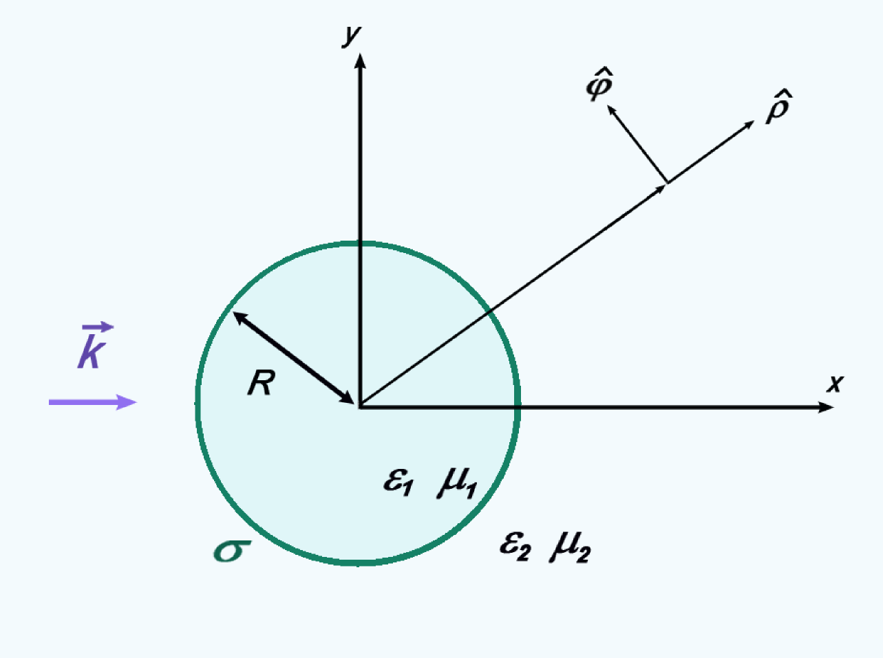
We consider a graphene–coated cylinder with circular cross–section (radius ) centered at =0, =0 (see Figure 1). The wire substrate may be dielectric or conducting (electric permittivity and magnetic permeability ) and the coated wire is embedded in a transparent medium (electric permittivity and magnetic permeability ). The graphene layer is treated as an infinitesimaly thin, local and isotropic two-sided layer with surface conductivity given by the Kubo formula [35, 36]. The wave vector of the incident radiation is directed along . In this case, the scattering problem can be handled in a scalar way since the solution to any incident polarization can be described as a linear combination of the solutions obtained in two fundamental scalar problems: electric field parallel to the main section of the cylindrical surface (p polarization or =0 modes) and magnetic field parallel to the main section of the cylindrical surface (s polarization or =0 modes).
To obtain analytical solutions to the scattering problem we closely follow the usual separation of variables approach [37, 38]. In a first step, the non-zero components of the total electromagnetic field along the axis of the cylinder for each polarization case, denoted by , are expanded as series of cylindrical harmonics, one for the internal region (, subscript 1) and another one for the external region (, subscript 2). When the incident electric field is contained in the plane (p polarization), the expansions for the total magnetic field along the axis of the cylinder are
| (1) | |||
| (2) |
where and are unknown complex coefficients, (), is the speed of light in vacuum, is the amplitude of the incident magnetic field (parallel to ) and and are the -th Bessel and Hankel functions of the first kind respectively. In the same manner, when the incident magnetic field is contained in the plane (s polarization), the expansions for the total electric field along the axis of the cylinder are
| (3) | |||
| (4) |
where is the amplitude of the incident electric field (parallel to ) and and unknown complex coefficients.
In a second step, the boundary conditions at are invoked to obtain the unknown coefficients , , and in terms of the incident amplitudes and . The boundary conditions for the graphene–coated cylinder are: i) the tangential component of the total electric field is continuous and ii) the discontinuity of the tangential component of the total magnetic field is proportional in magnitude to the surface current density (that is, to the graphene surface conductivity). In terms of , the boundary conditions at can be expressed as
| (5) |
for p polarization, and
| (6) |
for s polarization. Finally, the amplitudes of the scattered field can be written as
| (7) |
| (8) |
while the amplitudes of the fields inside the wire are given by
| (9) |
| (10) |
where , .
As in the problem of scattering by a wire without a graphene coating, the amplitudes given by equations (7)-(10) allow us to obtain the electromagnetic field everywhere in space as well as other quantities of interest such as differential, absorption and extinction cross–sections (see [37, 38] for details). The multipole coefficients and for the scattered field have essentially the same form as those corresponding to a bare wire [37, 38], except for additive corrections proportional to in numerator and denominator. Similar additive corrections have been recently reported for graphene-coated spheres [28].
3 Resonant excitation of localized surface plasmons
To simulate the electromagnetic response of graphene-coated cylinders we assume that , the complex surface conductivity of graphene, is given by the high frequency expression derived from Kubo formula (equation (1), Ref. [35]), including interband and intraband transition contributions. Apart from the angular frequency , the value of depends on the chemical potential (controlled with the help of a gate voltage), the ambient temperature and the carriers scattering rate . For the intraband () and interband () contributions to we have used the following expressions [35, 36]
| (11) |
| (12) |
where is the reduced Planck constant and the elementary charge. In all the calculations we have used K and meV.
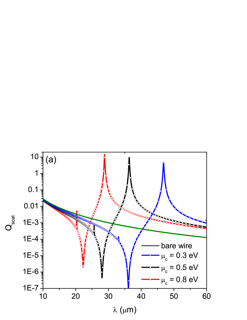
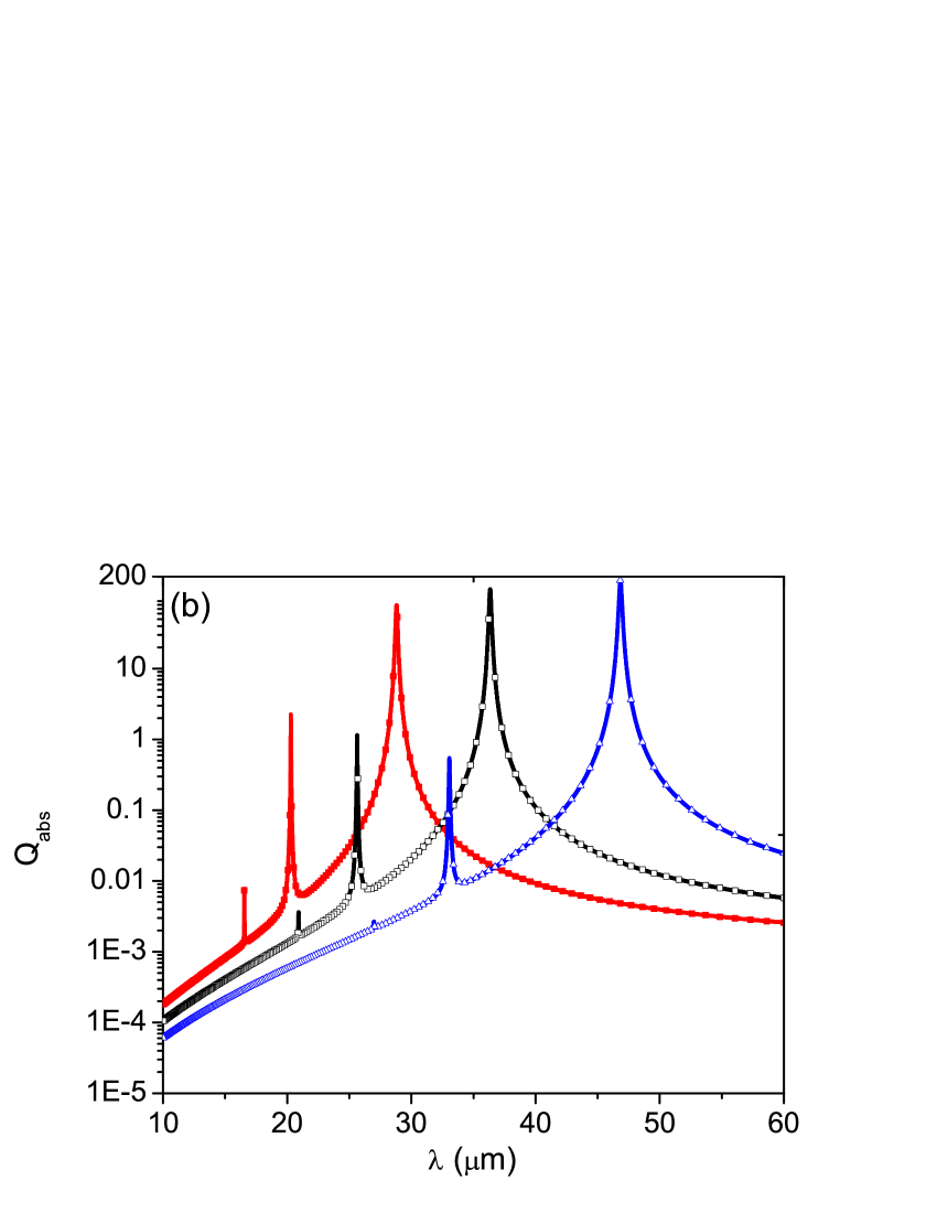
In Figure 2 we plot the scattering and absorption cross-sections (per unit length) for a wire with a radius m, made with a nonplasmonic, transparent material (, ) in a vaccum (). The excitation frequencies are in the range between THz (incident wavelength ) and THz (incident wavelength m), the incident wave is p-polarized and different values of have been considered. In Figure 2a the scattering cross-section spectrum of the bare wire (continuous line) is also given as a reference. The absorption cross-section of the bare wire vanishes identically and is not shown in Figure 2b. We see that while the scattering cross-section spectrum of the bare wire does not show any plasmonic feature in this spectral range, great enhancements in both the scattering and the absorption cross-section spectra occur at wavelengths near m ( eV), m ( eV) and m ( eV). At these spectral positions we obtain enhancement factors in the scattering cross-section of around four orders of magnitude. Other local maxima, particularly noticeable in the absorption cross-section spectra, occur at wavelengths near m, m (for eV), m, m, m (for eV) and m, m, m (for eV). The local maxima observed in the scattering and absorption cross-sections displayed in Figure 2 correspond to plasmonic resonances of the graphene-coated wire and can be obtained from the complex poles of the coefficients and of the multipole expansions for the electromagnetic field. The correspondence can be clearly seen by noting that the spectral positions of the peaks are in very good agreement with the real part of the complex wavelengths given in Table 1 (), with representing the complex root of the common denominator in equations (7) and (9), and . For the numerical calculation of we have used a Newton-Raphson method and the same parameters used for curves in Figure 2. We observe that the scattering cross-sections in Figure 2a display minima at wavelengths near m ( eV), m ( eV) and m ( eV). We found that the spectral position of these minima are in excellent agreement with the real part of the complex wavelengths where the numerator of the coefficient becomes zero. Taking into account that a minimization of the scattering cross-section is a necessary condition to obtain invisibility or transparency of an object, and that the scattering cross-section of the bare wire does not exhibit a minimum in this spectral range, the observation of these minima is relevant in the context of invisibility cloacks. These results, together with those shown in Figure 2, illustrate a great advantage of the graphene coating, which provides unprecedented control over the spectral location of the resonances of the wire via changes in the chemical potential , ultimately controlled through electrostatic gating.
The correspondence between plasmonic resonances of the graphene coating and the enhancement of scattering and absorption in the coated wire is further evidenced when the cross-sections of the same systems considered in Figure 2 are calculated for s-polarized –instead of p-polarized– illumination. In this case (not shown), no enhancements in the cross-sections of the graphene-coated wire are observed, which is consistent with the fact that localized surface plasmons are not supported in this polarization mode, since the electric field in the graphene coating can only induce electric currents directed along the wire axis, and not along the azimuthal direction , a necessary condition for the existence of localized surface plasmons in the graphene circular cylinder.
| eV | eV | eV | |
|---|---|---|---|
Table 1: Complex roots of in , where is the common denominator of the coefficients and and . The parameters correspond to those used to calculate the scattering and absorption cross-sections shown in Figure 2.
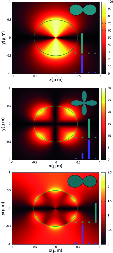
In Figure 3a we plot the spatial distribution of the electric field normalized to the incident amplitude for the wire considered in Figure 2 and eV. The incident wavelength is m, a value equal to the real part of the complex pole (see Table 1) of the multipole coefficients and and for which the strongest maxima in the scattering and absorption cross-sections for eV occur. We observe that the picture is very similar to that obtained for subwavelength metallic wires: the near fields are clearly of an electric dipole nature, with the dipolar moment oriented in the direction of the incident electric field (). However, contrary to the case of subwavelength metallic (impenetrable) wires, where the field cannot penetrate into the interior regions and is limited to a surface layer of approximately one skin depth thick, in the graphene-coated dielectric wire there are regions where the interior field can be greatly enhanced. Taking into account that the electric field induced in the scatterer is much stronger than that of incident radiation (see scale in Figure 3a), the far-field intensities are dominated by an electric dipole pattern, as indicated in the inset in Figure 3a, where we have sketched the angular distribution of scattered power for this excitation wavelength. When the incident wavelength is m, the scattering cross-section for eV (see Figure 2) exhibits a very weak peak while the absorption cross-section for the same value of exhibits a strong enhancement (an enhancement factor near three orders of magnitude greater than the non-resonant case). At this wavelength, the electric field induced in the scatterer, although not as strong, is again stronger than that of incident radiation and of a quadrupolar, not dipolar, nature. This is shown in Figure 3b, where we plot the map of normalized to the incident amplitude and calculated for the same parameters as in Figure 3a, except the incident wavelength m. Since the electric field induced in the scatterer is much stronger than that of incident radiation, the far-field intensities are dominated by an electric quadrupole pattern, as indicated in the inset in Figure 3a. In Figure 3c we show the map of , normalized to the incident amplitude, for the same parameters as in Figure 3a and 3b, except that now the incident wavelength is changed to m. For this value of and for eV a weak peak can be observed in the absorption cross-section, although no peak is observed in the scattering cross-section. We observe that the spatial distribution of the electric field induced in the scatterer at this excitation wavelength is hexapolar-shaped. However, the far-field intensities are dominated by an electric dipole pattern, as indicated in the bottom schematic diagram in Figure 3c) which illustrates the values of and , . Similar results have been obtained for the other values of chemical potential considered in Figure 2.
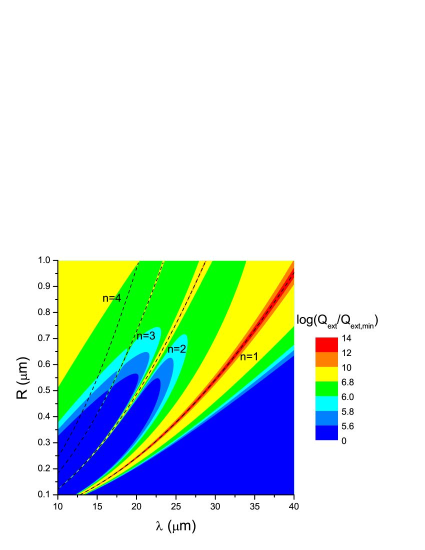
To investigate the size dispersion of the localized plasmonic modes of graphene-coated wires, we show in Figure 4 a color map of the extinction cross-section in the plane. The incident wave is -polarized, eV, the ambient medium is vacuum, and . We observe that the enhancements in the extinction cross-section follow the dashed lines labeled with . These lines indicate the resonance position, numerically obtained as the real part of the pole of the coefficient given by equation (7).
The examples so far highlight the attractive plasmonic features that a graphene coating can produce in intrinsically nonplasmonic wires. Next, we consider graphene-coated wires made of metallic or metallic-like substrates, that is, intrinsically plasmonic wires, where the localized surface plasmons of the graphene coating are expected to modify the localized plasmons already existing in the bare particle. We assume that the dispersive behavior of the interior electric permittivity is described by the Drude model
| (13) |
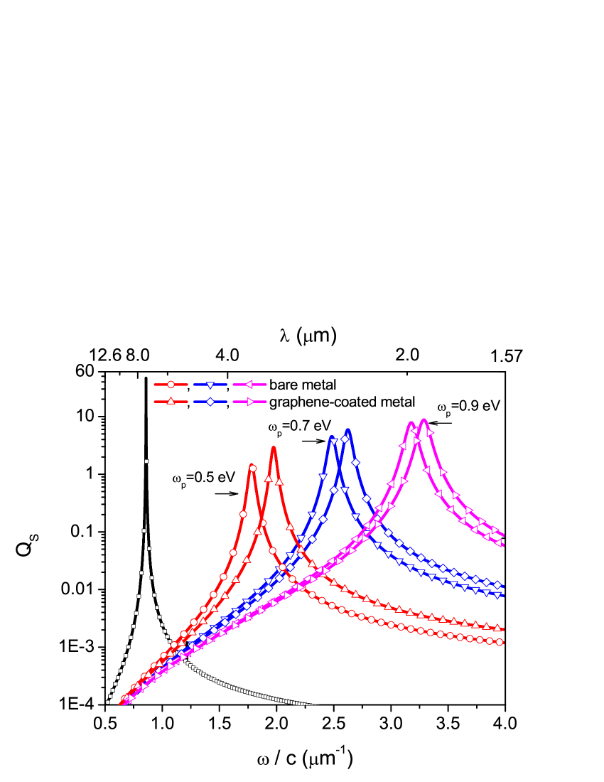
with the residual high-frequency response of the material, the metallic plasma frequency and the optical loss-rate of the Drude material. This model is applied to describe strongly doped semiconductors [39] which allow dynamic manipulation of carrier densities and have plasma frequencies in the same range that the realizable Fermi energies of graphene. Here the situation is similar to that reported for graphene-coated Drude spheres [28] in the sense that the region of induced charges in the graphene coating is not separated from the region of induced charges in the metallic substrate. For the case considered in this paper, both regions coincide with the cylindrical surface of radius and therefore a single hybridized plasmon is expected, rather than two (bonding and antibonding) hybridized plasmons with different energies, characteristic of systems where induced charges occur in two separated regions. In Figure 5 we plot the scattering cross-section spectrum in vacuum for a graphene-coated metallic wire with a radius nm illuminated under p polarization. The interior electric permittivity is given by equation (13) with , eV and different values of (0.5 eV, 0.7 eV and 0.9 eV), while the values of the complex surface conductivity of graphene have been obtained from the Kubo expression with K, meV and eV. The scattering cross-sections for the bare metallic cylinders and for an empty graphene cylinder in vacuum (black curve, and ) are also given as a reference. The excitation frequencies are in the range between THz (incident wavelength ) and THz (incident wavelength m).
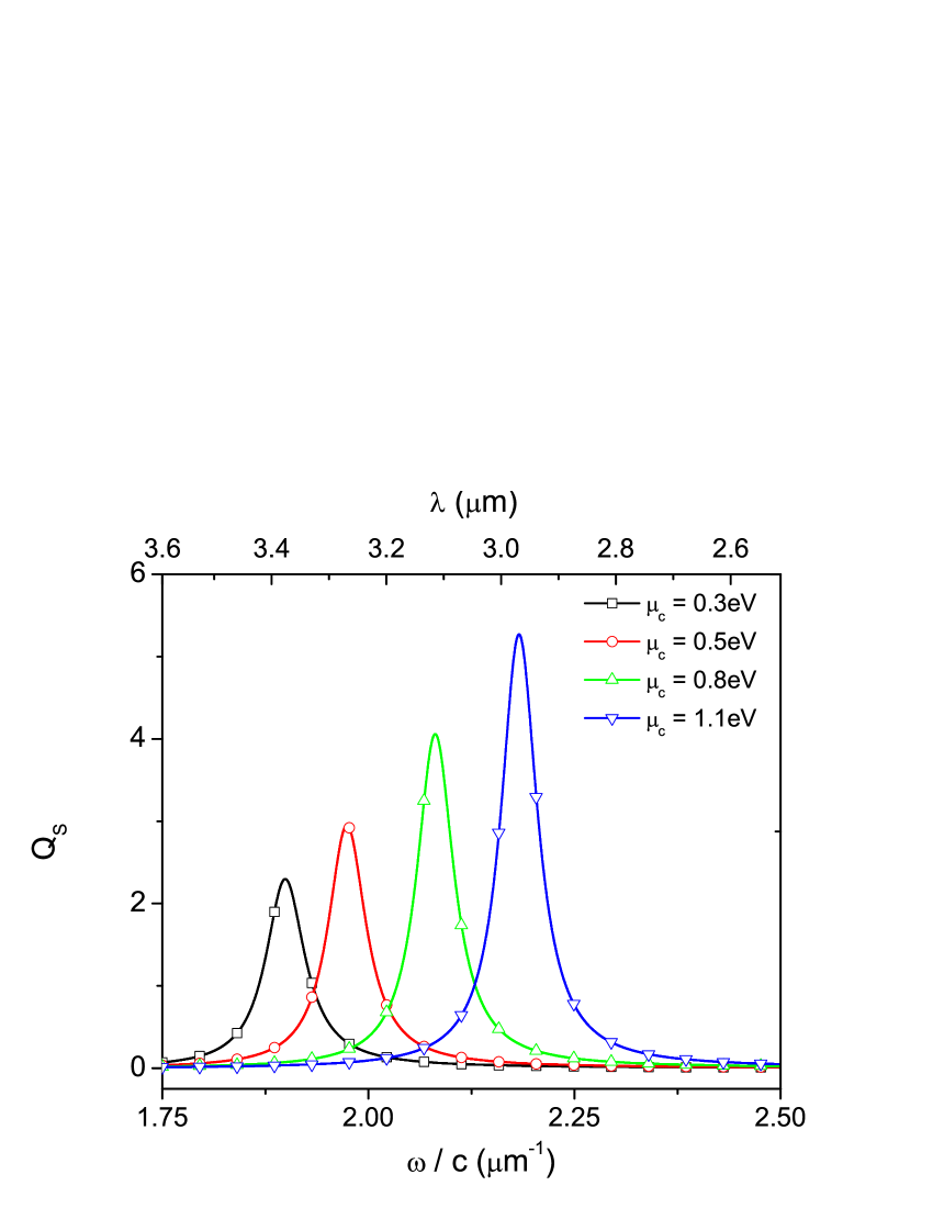
The curves in Figure 5 show that the hybridized resonances are always blueshifted compared to the resonances of the bare wire. This is consistent with the fact that the net effect of the graphene coating is to increase the induced charge density on the cylindrical surface of the metallic wire. The hybridized resonances can be controlled with the help of a gate voltage, which ultimately determines the value of the chemical potential . To explore the tunability of the hybridized resonances, in Figure 6 we give scattering cross-section spectra for a graphene-coated metallic wire ( 0.5eV) illuminated under p polarization for different values of the chemical potential (0.3eV, 0.5, 0.8 and 1.1 eV).
4 Summary
Fueled by recent experiments [29, 30, 31, 32] showing that, thanks to the van der Waals force, a graphene sheet can be tightly coated on a fiber surface, in this paper we have investigated the electromagnetic response of circular cross–section wires coated with a graphene monolayer. The emphasis has been centered around the plasmonic properties of the coated wire, a system that not only is interesting for several applications, but provides a simple canonical model for the plasmonic characteristics of other graphene–coated 2D particles. We developed an analytical method of scattering based on the separation of variables approach and obtained a rigorous solution in the form of an infinite series of cylindrical multipole partial waves. We presented examples for both dielectric (nonplasmonic) and metallic (plasmonic) wire substrates. In the first case the graphene coating introduces surface plasmons mechanisms which were absent in the bare particle. In the second case, there is an interaction between the plasmons supported independently by the bare metallic wire and those suported by the graphene coating. In both cases, the examples show that the good tunability of the graphene coating leads to unprecedented control over the location and magnitude of the particle plasmonic resonances.
Acknowledgments
The authors acknowledge the financial support of Consejo Nacional de Investigaciones Científicas y Técnicas, (CONICET, PIP 1800) and Universidad de Buenos Aires (project UBA 20020100100327).
References
References
- [1] Guo C F, Sun T Y, Cao F, Liu Q and Ren Z F 2014 Metallic nanostructures for light trapping in energy-harvesting devices Light: Sci. Appl. 3 e161
- [2] Lagendijk A, van Tiggelen B and Wiersma D 2009 Fifty years of Anderson localization Physics Today 62 (8) 24
- [3] Hashemi A, Hosseini-Farzad M and Montakhaba A 2010 Emergence of semi-localized Anderson modes in a disordered photonic crystal as a result of overlap probability Eur. Phys. J. B 77 147 152
- [4] John S 1987 Strong localization of photons in certain disordered dielectric superlattices Phys. Rev. Lett. 58 2486 2489
- [5] Fan X, Zheng W and Singh D J 2014 Light scattering and surface plasmons on small spherical particles Light: Sci. Appl. 3 e179
- [6] Bliokh K Y, Bliokh Y P, Freilikher V, Savelev S and Nori F 2008 Colloquium: Unusual resonators: Plasmonics, metamaterials, and random media Rev. Mod. Phys. 80 1201
- [7] Hutter E and Fendler J H 2008 Exploitation of Localized Surface Plasmon Resonance Adv. Mater. 16 1685 1706
- [8] Khatua S, Paulo P P R, Yuan H, Gupta A, Zijlstra P and Orrit M 2014 Resonant Plasmonic Enhancement of Single-Molecule Fluorescence by Individual Gold Nanorods ACS Nano 8 4440-4449
- [9] Talley C E, Jackson J B, Oubre C, Grady N K, Hollars C W, Lane S M, Huser T R, Nordlander P and Halas N J 2005 Surface-Enhanced Raman Scattering from Individual Au Nanoparticles and Nanoparticle Dimer Substrates Nano Lett. 5 1569 1574
- [10] West P R, Ishii S, Naik G V, Emani N K, Shalaev V M and Boltasseva A 2010 Searching for better plasmonic materials Laser & Photonics Reviews 4 795 808
- [11] Boltasseva A and Atwater H A 2011 Low-Loss Plasmonic Metamaterials Science 331 290-291
- [12] Boltasseva A and Atwater H A 2009 Plasmonics in graphene at infrared frequencies Phys. Rev. B 80 245435
- [13] Boltasseva A and Atwater H A 2013 Plasmons in graphene: Recent progress and applications Materials Science and Engineering R 74 351 376
- [14] Jablan M, Buljan H and Soljacic M 2009 Plasmonics in graphene at infrared frequencies Phys. Rev. B 80 (24) 245435
- [15] Nikitin A Y, Guinea F, García-Vidal F J and Martín-Moreno L 2011 Edge and waveguide terahertz surface plasmon modes in graphene microribbons Phys. Rev. B 84 161407
- [16] Christensen J, Manjavacas A, Thongrattanasiri S, Koppens F H and García de Abajo F J 2012 Graphene plasmon waveguiding and hybridization in individual and paired nanoribbons ACS Nano 6 (1) 431 440
- [17] Liu P, Zhang X, Ma Z, Cai W, Wang L and Xu J 2013 Surface plasmon modes in graphene wedge and groove waveguides Opt. Express 21 (26) 32432 32440
- [18] Bludov Y V, Vasilevskiy M I and Peres N M R 2010 Mechanism for graphene-based optoelectronic switches by tuning surface plasmon-polaritons in monolayer graphene EPL 92 68001
- [19] Slipchenko T M, Nesterov M L, Martín-Moreno L and Nikitin A Y 2013 Analytical solution for the diffraction of an electromagnetic wave by a graphene grating J. Opt. 15 114008
- [20] Gao W, Shi G, Jin Z, Shu J, Zhang Q, Vajtai R, Ajayan P M, Kono J, and Xu Q 2013 Excitation and Active Control of Propagating Surface Plasmon Polaritons in Graphene Nano Lett. 13 3698-3702
- [21] Peres N M R, Bludov Y V, Ferreira A and Vasilevskiy M I 2013 Exact solution for square-wave grating covered with graphene: surface plasmon-polaritons in the terahertz range J. Phys.: Condens. Matter 25 125303
- [22] Madani A and Entezar S R 2013 Optical properties of one-dimensional photonic crystals containing graphene sheets Physica B 431 1-5
- [23] Zhang Y, Wu Z, Cao Y and Zhang H 2015 Optical properties of one-dimensional Fibonacci quasi-periodic graphene photonic crystal Optics Communications 338 168-173
- [24] Zhu B, Ren G, Gao Y, Yang Y, Lian Y and Jian S 2014 Graphene-coated tapered nanowire infrared probe: a comparison with metal-coated probes Opt. Express 22 24096
- [25] Gao Y, Ren G, Zhu B, Liu H, Lian Y and Jian S 2014 Analytical model for plasmon modes in graphene-coated nanowire Opt. Express 22 24322
- [26] Gao Y, Ren G, Zhu B, Wang J and Jian S 2014 Single-mode graphene-coated nanowire plasmonic waveguide Opt. Lett. 39 5909
- [27] Huang Z-R, Wang L-L, Sun B, He M-D, Liu J-Q, Li H-J and Zhai X 2014 A mid-infrared fast-tunable graphene ring resonator based on guided-plasmonic wave resonance on a curved graphene surface J. Opt. 16 105004
- [28] Christensen T, Jauho A-P, Wubs M and Mortensen N 2015 Localized plasmons in graphene-coated nanospheres Phys. Rev. B 91 125414
- [29] He X, Liu Z, Wang D N, Yang M, Hu T Y and Tian J-G 2013 Saturable absorber based on graphene-coveredmicrofiber, IEEE Photon. Technol. Lett. 25 (14) 1392 1394
- [30] He X, Zhang X, Zhang H and Xu M 2014 Graphene covered on microfiber exhibiting polarization and polarization-dependent saturable absorption IEEE J. Sel. Top. Quantum Electron. 20 (1) 4500107
- [31] Wu Y, Yao B, Zhang A, Rao Y, Wang Z, Cheng Y, Gong Y, Zhang W, Chen Y and Chiang K S 2014 Graphene-coated microfiber Bragg grating for high-sensitivity gas sensing Opt. Lett. 39 (5) 1235 1237
- [32] Li W, Chen B, Meng C, Fang W, Xiao Y, Li X, Hu Z, Xu Y, Tong L, Wang H, Liu W, Bao J and Shen Y R 2014 Ultrafast all-optical graphene modulator Nano Lett. 14 (2) 955 959
- [33] Yang H, Hou Z, Zhou N, He B, Cao J and Kuang Y 2014 Graphene-encapsulated SnO2 hollow spheres as high-performance anode materials for lithium ion batteries Ceramics International 40 13903
- [34] Lee J-S, Kim S-I, Yoon J-C and Jang J-H 2013 Chemical Vapor Deposition of Mesoporous Graphene Nanoballs for Supercapacitor ACS Nano 7 6047
- [35] Falkovsky L A 2008 Optical properties of graphene and IV–VI semiconductors Physics Uspekhi 51 887–897
- [36] Milkhailov S A and Siegler K 2007 New Electromagnetic Mode in Graphene Phys. Rev. Lett. 99 016803
- [37] van de Hulst H C 1957 Light scattering by small particles (New York: John Wiley & Sons)
- [38] Bohren C F and Huffman D R 1983 Absorption and scattering of light by small particles (New York: John Wiley & Sons)
- [39] Schimpf A, Thakkar N, Gunthardt C, Masiello D and Gamelin D 2014 Charge-Tunable Quantum Plasmons in Colloidal Semiconductor Nanocrystals ACS Nano 8 1065