Study of electronic and magnetic properties and related x-ray absorption spectroscopy of ultrathin Co films on BaTiO3
Abstract
We present a first-principles study of electronic and magnetic properties of thin Co films on a BaTiO3(001) single crystal. The crystalline structure of 1, 2, and 3 monolayer thick Co films was determined and served as input for calculations of the electronic and magnetic properties of the films. The estimation of exchange constants indicates that the Co films are ferromagnetic with a high critical temperature, which depends on the film thickness and the interface geometry. In addition, we calculated x-ray absorption spectra, related magnetic circular dichroism (XMCD) and linear dichroism (XLD) of the Co L2,3 edges as a function of Co film thickness and ferroelectric polarization of BaTiO3. We found characteristic features, which depend strongly on the magnetic properties and the structure of the film. While there is only a weak dependence of XMCD spectra on the ferroelectric polarization, the XLD of the films is much more sensitive to the polarization switching, which could possibly be observed experimentally.
pacs:
75.50.Cc, 71.20.Lp, 71.15.RfThe interface between a magnetic thin film and a ferroelectric material is the subject of several recent investigations. Tsymbal and Kohlstedt (2006); Duan et al. (2006a, b); Sahoo et al. (2007); Velev et al. (2008); Fechner et al. (2008, 2009); Gruverman et al. (2009); Niranjan et al. (2009); Garcia et al. (2010); Vaz et al. (2010); Fechner et al. (2010); Cao et al. (2011); Meyerheim et al. (2011); Valencia et al. (2011); Borek et al. (2012); Lukashev et al. (2012); Dai et al. (2012); Lu et al. (2012) The major part of these studies is devoted to Fe/ferroelectric interfaces, Duan et al. (2006a); Sahoo et al. (2007); Velev et al. (2008); Fechner et al. (2008, 2009); Garcia et al. (2010); Fechner et al. (2010); Meyerheim et al. (2011); Valencia et al. (2011); Borek et al. (2012); Lukashev et al. (2012); Dai et al. (2012) since ferromagnetic iron is supposed to be a good candidate as a ferromagnetic electrode in two-component multiferroics. Although it was shown, that a ferroelectric film can be grown on an iron substrate and a functional heterojunction can be fabricated, Meyerheim et al. (2011); Valencia et al. (2011) the multiferroic effects by polarization switching were found to be not strong enough, since the main changes of the functional properties occur only in the vicinity of the interface. Duan et al. (2006a); Fechner et al. (2008); Valencia et al. (2011) Another impediment is non-ideal compatibility between an iron and an oxide surface. Until now it was not shown that junctions with symmetric interfaces, a highly desirable condition for coherent electronic transport, Tusche et al. (2005) can be grown. Accordingly, ferromagnetic oxides La1-xSrxMnO3 and SrRuO3 were used as electrodes in multiferroic junctions. Duan et al. (2006b); Gruverman et al. (2009); Niranjan et al. (2009); Vaz et al. (2010); Lu et al. (2012) Such interfaces can be almost ideally grown, but the Curie temperature of these oxides is too low for functional devices. Therefore, search for an appropriate ferromagnetic/ferroelectric interface is still in progress.
Among the above cited studies only few investigations deal with ultrathin ferromagnetic films on a ferroelectric substrate. Fechner et al. (2008, 2009, 2010); Borek et al. (2012) In particular, it was shown that two monolayer thick Fe films on the BaTiO3(001) surface might not be ferromagnetic because of the film geometry and magneto-elastic properties of iron. Fechner et al. (2008) Additionally, a substantial charge and spin moment transfer was found at the interface by altering the polarization direction. Fechner et al. (2008)
Thus, ultrathin films of Fe on a BaTiO3(001) single crystal are magnetically unstable, Fechner et al. (2008) but cobalt exhibits usually stable ferromagnetic characteristics in many nanostructures. Therefore, we continue our work on ultrathin metallic films on ferroelectric single crystals and suggest in this paper to use Co as the ferromagnetic material on BaTiO3(001).
Despite the comprehensive review about the progress in this field given by Vaz et al. Vaz et al. (2008) there are only few information about the interface of Co and perovskites like BaTiO3 (BTO). In the framework of spin-polarized DFT calculations, as implemented in the Vienna ab initio Simulation Package (VASP), multiferroic tunnel junctions of Co/BTO/Co were investigated by Cao et al. Cao et al. (2011) They showed that a critical thickness of BTO unit cells is necessary for the appearance of ferroelectricity, which is inhibited by a depolarizing electrostatic field, caused by dipoles at the ferroelectric-metal interfaces. Junquera and Ghosez (2003) In the work of Oleinik et al. Oleinik et al. (2001) first-principles calculations were applied on Co/STO/Co(001) magnetic tunnel junctions, where a strong covalent bond between Co and O and an induced magnetic moment of at the Ti atom was observed. This is similar to the case of Fe/BTO/Fe tunnel junctions. In another work, Polisetty et al. Polisetty et al. (2010) applied piezoelectrically controlled strain for electric tuning of exchange-bias fields of BTO/Co/CoO heterostructures.
In our first-principles study, we investigated systematically the crystalline structure of ultrathin Co films on BTO and their electronic and magnetic properties in dependence on the film thickness and the polarization of BTO. The calculations were performed using a so-called multi-code approach, in which atomic positions were obtained using a pseudo-potential code, VASP.Kresse and Hafner (1994); Kresse and Furthmüller (1996) This information serves as input for electronic and magnetic structure calculations with different multiple-scattering Green function methods. Lüders et al. (2001); Ebert et al. (2011); Ebert H. et al. (2009)
In addition, we simulated x-ray absorption spectra (XAS) and the related x-ray magnetic circular dichroism (XMCD), which is the method of choice to prove experimentally the change of the magnetic structure. The x-ray linear dichroism (XLD) is dicussed in respect to the occupation of orbitals. These methods are local and site-sensitive and offer the opportunity to investigate both the magnetic and structural properties as a function of layer thickness. Borek et al. (2012) So, we traced the dependence of XAS of Co L2,3 edges as a function of the Co film thickness and the polarization direction of BTO. All results were compared with the previous results for Fe thin films on BTO. Fechner et al. (2008); Borek et al. (2012)
Our paper is organized as follows. Our multi-code approach and computational details are presented in the next section I. Then, in sections II and III, we discuss structural, electronic, and magnetic properties of ultrathin Co films on BTO. Sections IV and V deal with computational simulations of XAS, XMCD, and XLD spectra. Conclusion is offered in section VI.
I Computational details
I.1 Structural optimization
The information about the crystalline structure of Co/BTO(001) was obtained using projector-augmented wave pseudo-potentials Blöchl (1994) implemented in the VASP code. Kresse and Hafner (1994); Kresse and Furthmüller (1996) The plane-wave basis was taken with a cutoff energy of . The calculations were performed within the local spin-density approximation (LSDA). We used the parametrization of Perdew and Wang for the exchange-correlation functional (PW-functional). Perdew and Wang (1992) Here, we believe that the impact of electronic correlations on the interface magnetoelectric coupling is minor.
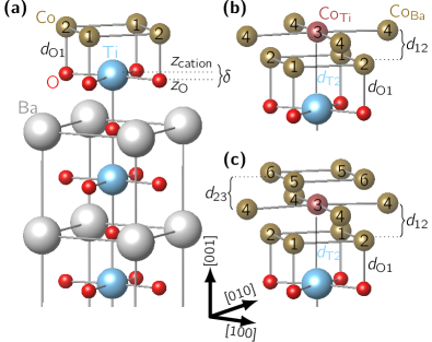
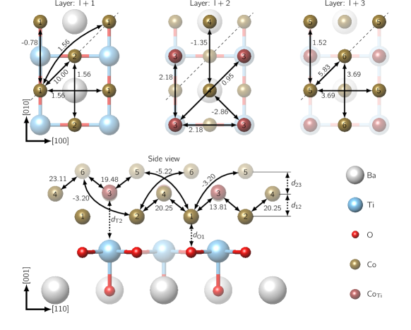
We performed the structural optimization of Co/BTO(001) in dependence on the Co film thickness and the ferroelectric polarization of BTO(001). To model the (001) surface of polar BTO, we constructed a 5 unit cells () thick supercell, with a vacuum spacer of along the [001] direction. The lattice parameters were set to the theoretical equilibrium values of tetragonal BTO: Fechner et al. (2008) and . The intralayer cation-oxygen displacements (see Fig. 1) in BTO cause the ferroelectric polarization, , along [001]. When is antiparallel to the surface normal (), the oxygen in each monolayer (ML) are higher then the cations (), and vice versa, the ferroelectric state means . Since the (001) surface of BTO is TiO2 terminated Fechner et al. (2008) for both directions of , the Co atoms find their relaxed positions atop the oxygen atoms. This is in agreement with the recent experimental data for Fe/BTO(001). Meyerheim et al. (2011) Each Co monolayer of the slab contains, therefore, two atoms per unit cell while the Co film thickness, , varies between one and three ML. For Co/BTO(001) the atomic positions of the four top BTO layers and all Co ML were allowed to relax. After the relaxation, the calculated forces are always less than . The Brillouin zone of the slab was sampled with a 10106 -point Monkhorst-Pack mesh Monkhorst and Pack (1976) during the force minimization.
I.2 Electronic and magnetic structure calculations
The relaxed geometry was used for further first-principles calculations using the multiple-scattering Green function method (Hutsepot) within the atomic sphere approximation to the crystal potential. Korringa (1947); Kohn and Rostoker (1954); Lüders et al. (2001) We took an angular momentum cutoff of for the Green function, a k-point mesh of for the BZ integration and 24 Gaussian quadrature points for complex energy contour integration. With the Green function of the system, all quantities of interest follow in a straightforward way. In particular, we are interested in ground state properties like the density of states (DOS) and the local magnetic moments Guo (1998) in dependence on Co film thickness and ferroelectric polarization direction of BTO.
To describe magnetic properties of Co/BTO(001), we calculated interatomic exchange coupling parameters using the magnetic force theorem implemented within the Green function method. Liechtenstein et al. (1987) The exchange coupling constants can be used to obtain spin-wave spectra by the diagonalization of the Heisenberg Hamiltonian
| (1) |
where and label magnetic atoms, is a unit vector in the direction of the magnetic moment of the -th atom and is the magnetic anisotropy energy (MAE), which is positive (negative) for the case of the easy-axis (easy-plane) anisotropy type. It can be calculated directly with the KKR method by using again the magnetic force theorem. Razee et al. (1997) The critical temperatures were estimated using a Monte Carlo (MC) simulation with the model Hamiltonian in Eq. (1). For the simulation, two dimensional supercells, which repeat the unit cell (see Fig. 1) , , and times in and direction were constructed. In those directions, we considered also periodic boundary conditions and restricted the calculation only to the magnetic atoms of the unit cell (2 Co atoms for , 4 Co atoms for , and 6 Co atoms for ). Within the supercell, the magnetic moment at lattice site interacts with its neighbors at the site via the first-principles . During a MC run, a lattice site with the magnetic moment vector was chosen and a new random direction was created. The energy of the system determines whether or was kept. Performing this procedure times on a lattice of sites is defined as one MC step. The starting point was a high-temperature disordered state above the critical temperature . In the course of the simulations, the temperature was stepwise reduced until magnetic ordering was reached. For each temperature , the thermal equilibrium was assumed to be reached after MC steps. The thermal averages were determined over additional MC steps. was then obtained from the temperature dependency of the magnetic susceptibility. With respect to fitting procedures and finite temperature sampling, all three supercells yielded the same critical temperature within an uncertainty range of . More details of our MC scheme can be found in Refs. Fischer et al., 2009; Otrokov et al., 2011a, b.
I.3 X-ray absorption spectra simulations
Using the self-consistent potentials of the scalar-relativistic Green function method (Hutsepot), the calculations were extended to a spin-resolved fully relativistic KKR code (SPR-KKR). Ebert H. et al. (2009) This Green function method Ebert H. et al. (2009) allows the calculation of x-ray absorption coefficients in dependence on the energy and the polarization of the x-rays. Koningsberger and Prins (1988); Stöhr et al. (1998); van der Laan (1996) For SPR-KKR calculations of magnetic moments, XAS and DOS, we have taken 144, 578 and 225 -points in the irreducible part of the Brillouin zone, respectively. The calculation of the structure constants were done using the Ewald method with parameter 2.0 and 4.0 in real space and reciprocal space, respectively. For the Ewald parameter connecting the summation in real and reciprocal space a value of 0.8 was used, making the summation in the real space converge faster. These parameters were applied for all considered Co/BTO systems.
II Crystalline structure of ultrathin Co films on BTO
| Co | Fe | ||||
| 1.778 | 1.784 | 1.774 | 1.781 | ||
| 1.856 | 1.853 | 1.857 | 1.855 | ||
| 1.116 | 1.107 | 1.049 | 1.054 | ||
| 3.022 | 2.927 | 2.971 | 2.918 | ||
| 1.827 | 1.829 | 1.843 | 1.849 | ||
| 1.183 | 1.179 | 1.218 | 1.241 | ||
| 1.154 | 1.153 | 1.134 | 1.114 | ||
| 3.094 | 3.014 | 3.214 | 3.121 | ||
| bulk (hcp): | 2.478 | ||||
For the ultrathin Co films deposited on BTO(001), the optimized interatomic distances are collected in Tab. 1, in comparison with the corresponding structure of Fe/BTO(001).Fechner et al. (2008); Borek et al. (2012) The definition of our distances are given in Fig. 1. Below in the text, the interface TiO2 layer is denoted as I for all films. The Co layers towards the surface are labeled , , and .
Structural relaxation, with the in-plane degrees of freedom for the layers starting with , energetically favors the structure with the Co sites in layer on top of the O sites in layer I. In the case of 1 ML Co (), the structure is similar to that of Fe/BTO(001).Fechner et al. (2008); Borek et al. (2012) For both multiferroic systems, the polarization state results in a slightly shorter distance, , between Co (Fe) and interfacial O.
When the Co film thickness increases to and 3, a distorted bodycentered tetragonal (bct) lattice is formed, although it is not typical for Co. Vaz et al. (2008) We found that the polarization reversal affects mainly the positions of interfacial Ti (I) and consequently those of the Co atoms, labeled as CoBa and CoTi, respectively (see Fig. 1). This is important concerning the magnetic properties of the films.
III Electronic and magnetic properties of ultrathin Co films on BTO
In order to determine the magnetic ground state for the three film thicknesses, we calculated the total energy for the ferromagnetic (FM) and antiferromagnetic (AFM) configurations of the magnetic moments of the Co atoms. In all cases, the FM solution was preferable, independent of thickness or polarization. So, the thin cobalt films are strong ferromagnets and show a lower sensitivity to structural transformations then the iron layers, which showed a considerable change in the magnetic order for different layer thicknesses. For the 2 ML Fe film on BTO, the in layer was almost quenched while the sizable moments in the surface layer are ordered antiparallel. This results in a total magnetic moment of . Deposition of a third Fe monolayer restored the ferromagnetic order of the 1 ML Fe film.
III.1 Magnetic moments and density of states
| Co | |||||||
|---|---|---|---|---|---|---|---|
| CoBa | |||||||
| CoTi | |||||||
| Co | |||||||
| O | I | ||||||
| Ti | I | ||||||
| Co bulk (hcp): | |||||||
| Co | |||||||
|---|---|---|---|---|---|---|---|
| CoBa | |||||||
| CoTi | |||||||
| Co | |||||||
| Co bulk (hcp): | |||||||
| Co6 | |||||||
|---|---|---|---|---|---|---|---|
| Co5 | |||||||
| Co4 | |||||||
| Co3 | |||||||
| Co2 | |||||||
| Co1 | |||||||
The calculated spin moments (see Tab. 2) for the Co atoms show a strong dependence on the geometry of the films and the hybridization of Co states with the electronic bands of the substrate. The different environment of e.g. CoBa and CoTi, in particular, the atomic volumes and the band hybridization, influences also these moments.
In the case of and , the spin moments for Co atoms at the surface, are larger then for the Co bulk (hcp) because of the symmetry reduction and an enhanced volume per Co atom. The Co magnetic moments in layer for approach their bulk value. For , the spin moments of Co and CoTi are smaller in comparison to , because of slightly elongated distances and , respectively. In the case of , we observe for all three layers a quenching of the spin moment in comparison to Co bulk (hcp), which results from a strong reduction of the volume per Co atom.
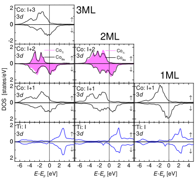
Besides, we also observe induced magnetic moments at the Ti and O atoms at the interface (see Tab. 2). For the Ti atoms, these induced magnetic moments are antiparallel oriented to the direction of the magnetic moments of the Co atoms and are originated, similar to the case of Fe/BTO(001), from the hybridization of Ti and Co states (see Fig. 2). The strong interaction between the host and the Co films widens the DOS of the layers at the interface, while the states of Co become very narrow towards the surface, which results from the reduced coordination number of Co atoms at the surface (in comparison to Co bulk). The impact of the crystalline environment is very strong on the DOS and magnetic moments of the Co atoms. As the result, the magnetic moments on CoTi are smaller by then on CoBa() due to the strong interaction between the CoTi and the Ti states. A short distance between Co() and Co() and a strong Co-Co hybridization in the case of leads to a substantial reduction of magnetic moments of the surface Co layer.
We have calculated the orbital moment of Co atoms along (see Tab. 3) and along (see Tab. 4). In the last case, the two Co atoms in each layer are nonequivalent. In the surface layer the atoms show a strong dependence on the electric polarization of the substrate. For the influence of the polarization is weak and is as large as for the Fe/BTO system. Borek et al. (2012)
Duan et al. Duan et al. (2008) predicted that the magnetic anisotropy of thin magnetic films may be effected by the polarization of the ferroelectric substrate. His calculations done for 1 ML Fe/BTO gave differences for the orbital magnetic moment of and for and , respectively. In our former work of 1 ML Fe/BTO, we found also an averaged anisotropy of the orbital magnetic moment of and (note that there are two Fe atoms in the unit cell of 1 ML Fe). Borek et al. (2012) In case of 1 ML Co/BTO, we get the averaged for the polarization , which is similar to 1 ML Fe/BTO. There was no strong dependence on the polarization on the BTO substrate in our calculations. The anisotropies for the orbital moment will influence the preference of the easy axis of magnetization as discussed in the next section.
On the other hand, for thicker Co films, the electronic structure can be strongly affected by a Schottky barrier, which develops at a semiconductor-metal interface and can lead to a spurious charge transfer across the interface. Stengel et al. (2011) However, in very thin metallic films on a semiconductor, the Schottky barrier is not significant and can not substantially modify their electronic and magnetic structure.
III.2 Magnetic interactions and Curie temperatures
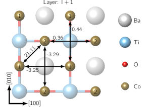
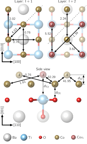
To study magnetic interactions in ultrathin Co films on BTO(001), we computed the exchange constants which enter the Heisenberg model (1). The most significant magnetic exchange interactions for Co/BTO(001) are shown in Figs. 3 to 5 for 2, 3 ML, respectively, while for the sake of completeness all calculated coupling constants are presented in the supplementary material. They are always separated in interlayer and intralayer contributions.
The key feature of the elaborated results is a very strong magnetic coupling between the nearest neighbors. This means for the 1 ML Co film the nearest neighbor coupling is in-plane (nearest neighbor Co distance is ) with about (see Fig. 3). In this case the electronic density is mainly distributed within the -plane and the exchange integrals represent an overlap between the electronic wave functions. Hence, comparing with Co bulk (hcp) the magnetic coupling in 1 ML remains stronger despite the larger nearest neighbor distance (in Co bulk (hcp) the nearest neighbor magnetic coupling is ).
In contrast, for the films with an out-of-plane component (2 ML, 3 ML), the distances towards the Co atoms in the next layer are shorter (). Therefore, the nearest neighbor coupling is now between those layers and the wave function overlap is even stronger. It leads to a strong magnetic interaction between for 2 ML (see Fig. 4). In the case of 3 ML, the electronic density redistributes in all directions and, therefore, the strength of the interlayer exchange interactions with respect to those of 2 ML is reduced to (see Fig. 5). Comparing these results with the exchange constants in Co bulk, we found in general a strong asymmetry between in-plane and out-of-plane components. The latter are larger while the in-plane directions are strongly reduced (see Figs. 4 and 5).
Furthermore, we obtain a partial mediation of the magnetic coupling by the BTO host. The exchange interaction between e.g. the second nearest neighbor Co atoms depends on the underlying atom, either or with mediating Ba or Ti, respectively (see Fig. 3). This fact can also be observed for 2 and 3 ML (see Figs. 4 and 5) and is evident from the comparison of the calculated for supported and unsupported thin Co films, shown in the supplementary material. While using the same geometry for the Co films, we removed the BTO substrate in the calculations. Immediately, the symmetry of and directions returns and some exchange interaction values differ more than .
| () | () | |||
|---|---|---|---|---|
| 360 (307) | 298 (250) | |||
| 844 (820) | 818 (780) | |||
| 567 (550) | 580 (550) | |||
For the Monte Carlo simulations with the classical Heisenberg Hamiltonian (1), we have also computed the magneto-crystalline anisotropy energy (MAE) for various Co thicknesses and polarizations (see Table 5). We found an out-of-plane magnetization direction for the cases of 1 and 3 ML Co/BTO(001), while in the case of 2 ML Co/BTO(001), the magnetization direction is in-plane. The change in the MAE with the polarization switch can reach up to . It is remarkable, that in the 2 ML Co case, the magnetization direction is lying within the -plane, which can be explained by the small interlayer distance (see Table I).
Together with the calculated parameters, those MAE values were used to determine the critical temperatures in dependence on the layer thickness and polarization (see Table 5). In general, the thin (Co)L/BTO films are ferromagnetic at room temperature for .
The increases not monotonically with the thickness, as expected from the large change of the magnetic coupling parameters. The main contribution originates from the strong interlayer coupling. The different polarization directions have only a small influence to the the value of which follows from the similar parameters for or (for all values see the supplementary material). As expected, a value for MAE increases the Curie temperature (see Table 5).
IV XAS and XMCD
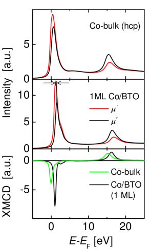
The Co L2,3 edges are in the focus of our XMCD discussion. We have calculated x-ray absorption spectra of right- and left-circular polarized x-ray radiation in dependence on the Co film thickness and the electric polarization direction of BTO. The difference of the absorption coefficients is normalized to the number of Co atoms in the multilayers. All x-ray absorption spectra were broadened by Lorentz convolution with a core hole width of and for the L2 and L3 edge, respectively. In our simulations of XAS and XMCD the magnetization , the electric polarization and the incidence of light are parallel to the -axis (surface normal) of the Co/BTO(001) system.
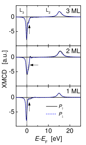
In Fig. 6 the calculated x-ray spectra (upper part) and the related difference spectra (lower part) are shown for 1 ML Co/BTO(001) () in comparison to calculations performed for Co bulk (hcp). The results of our XMCD calculations for (Co)L/BTO with and and are summarized in Fig. 7.
In all cases, we observe the well-known energy dependence of XMCD (Fig. 7), where the intensity at the L3 (L2) edge is decreased (enhanced) due to different selection rules of spin-up and spin-down electrons in the ferromagnetic phase. The behavior is opposite at the L3 (L2) edge in case of . The dependence on the electric polarization of BTO is in all cases very weak (see dotted lines in Fig. 7).
In comparison to Co bulk, we found small but significant differences concerning ultrathin films. Note that the maxima of the L edges of left and right circularly polarized light are not at the same energetic position as observed for Co bulk XAS (see open arrows in Fig. 6). This can be attributed (as in the case of Fe/BTO Borek et al. (2012)) to the cancellation of degenerate states at the interface or/and surface of the film.
In the energy dependence of the L3 edge, we observe a small structure of the XMCD peak at higher energy (see closed arrows in Fig. 7) in dependence on layer thickness. The appearance of this structure can also be explained if we consider the spin- and layer-resolved DOS (not shown here) of states as demonstrated for the system Fe/BTO. Borek et al. (2012) In general, it is possible to separate all the different contributions by means of layer-resolved XMCD calculations. This dependence on layer thickness should show up in corresponding experiments.
V X(M)LD
X-ray absorption linear dichroism can be applied in different modes. Stöhr and Siegmann (2006) In nonmagnetic materials with cubic symmetry the x-ray absorption intensity is independent on the orientation of the polarization vector of light () relative to the sample. As the symmetry is lowered (like in a film), the intensity is directly proportional to the number of empty valence states in the direction of . The polarization vector acts like a search light for the direction of maximum and minimum empty valence states. Stöhr and Siegmann (2006) In case of a magnetic sample with cubic symmetry, the spin-orbit coupling leads to magnetic linear dichroism, where the x-ray absorption intensity is different for aligned parallel and perpendicular to the spin direction. Stöhr et al. (1998) This kind of dichroism is often considered in the discussion of magneto crystalline effects (for example in Ref. Kune and Oppeneer, 2003).
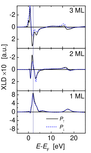
In our magnetic ultrathin Co films on BTO we have both natural and magnetic linear dichroism effects. First, we present results for a fixed direction of magnetization and linearly polarized light with polarization along () and (), respectively. The difference between both x-ray absorption spectra is shown in Fig. 8.
The strong dependence of the XLD on film thickness can be related to the occupation of orbitals. A detailed analysis is possible concerning the single contributions of the initial () state to the transitions of the different Co absorbers in the film. In the 1 ML case, we get the main positive contribution from the transition of into states. The contributions of and are small because of the strong interaction between Co and Ti atoms at the interface. The XLD of 2 ML reflects the change of occupancy between in-plane and out-of-plane orbitals. In the 3 ML case, we found that the behavior is similar to the Co bulk, but with much more fine structures. These fine structures are related to the lifting of degeneracy in the final state in the thin film.
Besides, we found that the XLD is much more sensitive concerning the dependence on the polarization of the BTO substrate as the XMCD. This emphasize how the reversal of polarization changes the occupation of states.
We have also investigated x-ray absorption in dependence on the magnetization direction for fixed polarization but spin-orbit interaction and crystal field are both to weak to eliminate magneto crystalline anisotropy.
VI Conclusion
In this first-principles study of structural, electronic, and magnetic properties of ultrathin Co layers on the BaTiO3(001) substrate, we showed, that the crystalline structure of (Co)L/BTO(001) () interfaces is very similar to the one of (Fe)L/BTO(001) films presented in our previous study. Fechner et al. (2008) Additionally, we found also for the Co layers only a small dependence on the polarization direction of the substrate for all investigated properties. However, in contrary to the Fe/BTO(001) case, Co films on BTO(001) exhibit a stable ferromagnetic ordering at room temperature which depends strongly on the layer thickness and is the strongest for . The magnetic interaction is mainly featured by the coupling between the nearest neighbors. For cases, the strongest interactions arise between the adjacent layers, while the intralayer magnetic coupling was found to be rather weak. This results from short interlayer distances leading to a strong hybridization between Co electrons of adjacent layers. Surprisingly, the easy axis turns for 2 ML from a out-of-plane magnetization (in and 3) to a in-plane magnetization, which was obtained from the direct calculation of the MAE or the calculated orbital moments.
For a comparison to possible experimental measurements, we simulated x-ray absorption spectra and related x-ray magnetic circular and (magnetic) linear dichroism to trace the change of the spectra under the polarization switching in the BTO substrate. While the XMCD depends only weakly on the substrate polarization, similar to our previous study for (Fe)L/BTO(001) films, Borek et al. (2012) the XLD shows indeed significant changes under polarization switching, which can probably be observed experimentally.
Acknowledgements.
We are grateful for financial support by Deutsche Forschungsgemeinschaft in the framework of SFB762 ”Functionality of Oxide Interfaces”. The authors would like to thank Jan Minár and Hubert Ebert for deployment and support of the SPR-KKR program and helpful discussions.References
- Tsymbal and Kohlstedt (2006) E. Y. Tsymbal and H. Kohlstedt, Science 313, 181 (2006).
- Duan et al. (2006a) C.-G. Duan, S. S. Jaswal, and E. Y. Tsymbal, Phys. Rev. Lett. 97, 047201 (2006a).
- Duan et al. (2006b) C.-G. Duan, R. F. Sabirianov, W.-N. Mei, S. S. Jaswal, and E. Y. Tsymbal, Nano Lett. 6, 483 (2006b).
- Sahoo et al. (2007) S. Sahoo, S. Polisetty, C.-G. Duan, S. S. Jaswal, E. Y. Tsymbal, and C. Binek, Phys. Rev. B 76, 092108 (2007).
- Velev et al. (2008) J. P. Velev, C.-G. Duan, K. D. Belashchenko, S. S. Jaswal, and E. Y. Tsymbal, J. Appl. Phys. 103, 07A701 (2008).
- Fechner et al. (2008) M. Fechner, I. V. Maznichenko, S. Ostanin, A. Ernst, J. Henk, P. Bruno, and I. Mertig, Phys. Rev. B 78, 212406 (2008).
- Fechner et al. (2009) M. Fechner, S. Ostanin, and I. Mertig, Phys. Rev. B 80, 094405 (2009).
- Gruverman et al. (2009) A. Gruverman, D. Wu, H. Lu, Y. Wang, H. W. Jang, C. M. Folkman, M. Y. Zhuravlev, D. Felker, M. Rzchowski, C.-B. Eom, et al., Nano Lett. 9, 3539 (2009), URL http://dx.doi.org/10.1021/nl901754t.
- Niranjan et al. (2009) M. K. Niranjan, J. D. Burton, J. P. Velev, S. S. Jaswal, and E. Y. Tsymbal, Appl. Phys. Lett. 95, 052501 (2009).
- Garcia et al. (2010) V. Garcia, M. Bibes, L. Bocher, S. Valencia, F. Kronast, A. Crassous, X. Moya, S. Enouz-Vedrenne, A. Gloter, D. Imhoff, et al., Science 327, 1106 (2010), URL http://www.sciencemag.org/content/327/5969/1106.abstract?sid=fa10090a-6a64-4473-b9df-5eef4cb8bef0.
- Vaz et al. (2010) C. A. F. Vaz, J. Hoffman, Y. Segal, J. W. Reiner, R. D. Grober, Z. Zhang, C. H. Ahn, and F. J. Walker, Phys. Rev. Lett. 104, 127202 (2010).
- Fechner et al. (2010) M. Fechner, I. V. Maznichenko, S. Ostanin, A. Ernst, J. Henk, and I. Mertig, Phys. Status Solidi B 247, 1600 (2010).
- Cao et al. (2011) D. Cao, M.-Q. Cai, W. Y. Hu, and C.-M. Xu, J. Appl. Phys. 109, 114107 (2011).
- Meyerheim et al. (2011) H. L. Meyerheim, F. Klimenta, A. Ernst, K. Mohseni, S. Ostanin, M. Fechner, S. Parihar, I. V. Maznichenko, I. Mertig, and J. Kirschner, Phys. Rev. Lett. 106, 087203 (2011).
- Valencia et al. (2011) S. Valencia, A. Crassous, L. Bocher, V. Garcia, X. Moya, R. O. Cherifi, C. Deranlot, K. Bouzehouane, S. Fusil, A. Zobelli, et al., Nat. Mater. 10, 753 (2011).
- Borek et al. (2012) S. Borek, I. V. Maznichenko, G. Fischer, W. Hergert, I. Mertig, A. Ernst, S. Ostanin, and A. Chassé, Phys. Rev. B 85, 134432 (2012).
- Lukashev et al. (2012) P. V. Lukashev, J. D. Burton, S. S. Jaswal, and E. Y. Tsymbal, J. Phys.: Condens. Matter 24, 226003 (2012).
- Dai et al. (2012) J.-Q. Dai, Y.-M. Song, and H. Zhang, J. Appl. Phys. 111, 114301 (2012).
- Lu et al. (2012) H. Lu, T. A. George, Y. Wang, I. Ketsman, J. D. Burton, C.-W. Bark, S. Ryu, D. J. Kim, J. Wang, C. Binek, et al., Appl. Phys. Lett. 100, 232904 (2012).
- Tusche et al. (2005) C. Tusche, H. L. Meyerheim, N. Jedrecy, G. Renaud, A. Ernst, J. Henk, P. Bruno, and J. Kirschner, Phys. Rev. Lett. 95, 176101 (2005).
- Vaz et al. (2008) C. A. F. Vaz, J. A. C. Bland, and G. Lauhoff, Rep. Prog. Phys. 71, 056501 (2008).
- Junquera and Ghosez (2003) J. Junquera and P. Ghosez, Nature 422, 506 (2003).
- Oleinik et al. (2001) I. I. Oleinik, E. Y. Tsymbal, and D. G. Pettifor, Phys. Rev. B 65, 020401 (2001).
- Polisetty et al. (2010) S. Polisetty, W. Echtenkamp, K. Jones, X. He, S. Sahoo, and C. Binek, Phys. Rev. B 82, 134419 (2010).
- Kresse and Hafner (1994) G. Kresse and J. Hafner, Phys. Rev. B 49, 14251 (1994).
- Kresse and Furthmüller (1996) G. Kresse and J. Furthmüller, Phys. Rev. B 54, 11169 (1996).
- Lüders et al. (2001) M. Lüders, A. Ernst, W. M. Temmerman, Z. Szotek, , and P. J. Durham, J. Phys.: Condens. Matter 13, 8587 (2001).
- Ebert et al. (2011) H. Ebert, D. Ködderitzsch, and J. Minár, Rep. Prog. Phys. 74, 096501 (2011).
- Ebert H. et al. (2009) Ebert H. et al., The Munich SPR-KKR package, version 5.4 (2009), Available online at http://olymp.cup.uni-muenchen.de/ak/ebert/SPRKKR.
- Blöchl (1994) P. E. Blöchl, Phys. Rev. B 50, 17953 (1994).
- Perdew and Wang (1992) J. P. Perdew and Y. Wang, Phys. Rev. B 45, 13244 (1992).
- Monkhorst and Pack (1976) H. J. Monkhorst and J. D. Pack, Phys. Rev. B 13, 5188 (1976).
- Korringa (1947) J. Korringa, Physica 13, 392 (1947).
- Kohn and Rostoker (1954) W. Kohn and N. Rostoker, Phys. Rev. 94, 1111 (1954).
- Guo (1998) G. Y. Guo, Phys. Rev. B 57, 10295 (1998).
- Liechtenstein et al. (1987) A. I. Liechtenstein, M. I. Katsnelson, V. P. Antropov, and V. A. Gubanov, J. Magn. Magn. Mater. 67, 65 (1987).
- Razee et al. (1997) S. S. A. Razee, J. B. Staunton, and F. J. Pinski, Phys. Rev. B 56, 8082 (1997).
- Fischer et al. (2009) G. Fischer, M. Däne, A. Ernst, P. Bruno, M. Lueders, Z. Szotek, W. Temmerman, and W. Hergert, Phys. Rev. B 80, 014408 (2009).
- Otrokov et al. (2011a) M. M. Otrokov, A. Ernst, S. Ostanin, G. Fischer, P. Buczek, L. M. Sandratskii, W. Hergert, I. Mertig, V. M. Kuznetsov, and E. V. Chulkov, Phys. Rev. B 83, 155203 (2011a), URL http://link.aps.org/doi/10.1103/PhysRevB.83.155203.
- Otrokov et al. (2011b) M. M. Otrokov, A. Ernst, V. V. Tugushev, S. Ostanin, P. Buczek, L. M. Sandratskii, G. Fischer, W. Hergert, I. Mertig, V. M. Kuznetsov, et al., Phys. Rev. B 84, 144431 (2011b), URL http://link.aps.org/doi/10.1103/PhysRevB.84.144431.
- Momma and Izumi (2011) K. Momma and F. Izumi, J. Appl. Crystallogr. 44, 1272 (2011).
- Koningsberger and Prins (1988) D. Koningsberger and R. Prins, eds., X-Ray Absorption: Principles, Applications, Techniques of EXAFS, SEXAFS and XANES (John Wiley Sons, Inc., 1988).
- Stöhr et al. (1998) J. Stöhr, H. A. Padmore, S. Anders, T. Stammler, and M. R. Scheinfein, Surf. Rev. Lett. 5, 1297 (1998).
- van der Laan (1996) G. van der Laan, J. Magn. Magn. Mater. 156, 99 (1996).
- Lejaeghere et al. (2014) K. Lejaeghere, V. Van Speybroeck, G. Van Oost, and S. Cottenier, Crit. Rev. Solid State Mater. Sci. 39, 1 (2014).
- Duan et al. (2008) C.-G. Duan, J. P. Velev, R. F. Sabirianov, Z. Zhu, J. Chu, S. S. Jaswal, and E. Y. Tsymbal, Phys. Rev. Lett. 101, 137201 (2008).
- Stengel et al. (2011) M. Stengel, P. Aguado-Puente, N. A. Spaldin, and J. Junquera, Phys. Rev. B 83, 235112 (2011).
- Stöhr and Siegmann (2006) J. Stöhr and H. Siegmann, Magnetism (Springer Berlin Heidelberg, 2006).
- Kune and Oppeneer (2003) J. Kune and P. Oppeneer, Phys. Rev. B 67, 024431 (2003).