Compliant substrate epitaxy: Au on MoS2
Abstract
The epitaxial growth of {111} oriented Au on MoS2 is well documented despite the large lattice mismatch (% biaxial strain), and the fact that a Au {001} orientation results in much less elastic strain. An analysis based on density functional and linear elasticity theories reveals that the {111} orientation is stabilized by a combination of favorable surface and interfacial contributions to the energy, and the compliance of the first layer of the MoS2.
pacs:
81.15.-z,68.35.bf,68.35.GyThe electronic and optical properties of transition metal dichalcogenides show much promise for technological applications Radisavljevic et al. (2011). Incorporating this material within devices will require either the growth of the dichalcogenides on other substrates, or growth of other materials on a dichalcogenide substrate. In this respect, the growth of Au on MoS2 can be viewed as a prototypical system.
The growth of Au on MoS2 was studied in the mid to late 1960’s using early in situ and ex situ transmission electron microscopy Jacobs and Stowell (1965); Jesser and KuhlmannWilsdorf (1967); Honjo and Yagi (1969); Pashley et al. (1964); Jacobs et al. (1966). Au was deposited on MoS2 using evaporation, and was discovered to grow predominantly with a plate-like geometry in a {111} orientation. The directions of the Au platelets were nearly aligned along the direction of the substrates. Similar orientations were observed for Ag nuclei Jacobs et al. (1966).
The growth and evolution of the Au films were modeled using theory available at the time Jesser and Kuhlmann-Wilsdorf (1967); Jesser and KuhlmannWilsdorf (1967). This theory, however, was rooted in an phenomenological understanding of the interfacial properties. Moreover, the substrate was treated as a typical bulk, and no accounting for the influence of the van der Waals (VDW) bonding within the substrate layers was attempted. Further, the Au clusters were approximated as spherical caps, as the TEM images did not allow for measurement of island thicknesses. Finally, only the {111} orientation was considered in any detail.
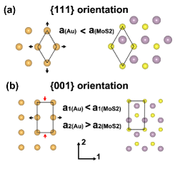
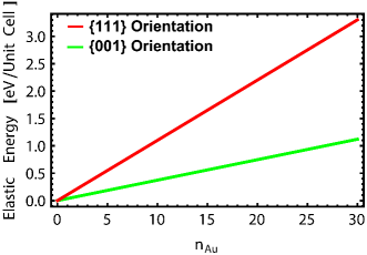
In the most simple model of epitaxy, the substrate is assumed infinite, and as a consequence, it does not relax during the growth process. For Au on MoS2, two possible orientations of the growing film are shown in Fig. 1. For the {111} orientation, the biaxial strain required in the film is approximately 8%. In contrast, the {001} oriented film the strains are approximately -6% and 8% in the directions shown. Based on these strains, one would expect that the {001} orientation would be much more favorable, and consequently would be predominantly the experimentally observed orientation. Figure 2 compares the elastic energies of the two films (neglecting surface and interfacial stresses and energies) as a function of the number of layers of Au grown assuming the substrate is rigid. Clearly, the elastic energy of the {111} orientation is much larger than that of the {001} orientation. This observation raises a fundamental questions regarding the growth: Why is the predominant orientation {111} and not {001}?
In the following paragraphs a model to explain the experimentally observed film orientation is developed. The model assumes that due to the weak VDW bonding between layers of MoS2, the surface layer is able to relax nearly independently of the remaining bulk layers. The compliance of the substrate, when coupled with the surface and interface energies (including strain energies) results in a lower formation energy for the {111} orientation as compared with the {001} orientation, in agreement with experiment.
The model is built on two types of calculations. First, a continuum linear elastic model for the epitaxial growth of Au on MoS2 including the relaxation of the substrate and the influence of surface/interface energies and strains is developed. The parameters for this model are then determined using density functional theory (DFT) based electronic structure total energy methods.
The continuum linear elastic model is developed by proposing a “synthesis path” and then computing the energy contributions along this path. (Note that this path is not necessarily experimentally accessible. It simply facilitates computation.) The initial step in forming an epitaxial layer can be taken as the extraction of a thin slab of the growing material from a bulk crystal. This extraction creates two surfaces, and the energy of the slab is increased by the surface energies (that reflect any strain in the as produced surfaces). The next step is to strain the film to its final strain in its epitaxially bonded state. This contributes the strain energy of the bulk plus any contribution to the strain energy from the surfaces. The third step is to separate the first substrate layer from rest of the substrate to create a freestanding MoS2 layer. This adds a layer separation energy to the system. In the fourth step, this free-standing layer is then strained introducing the strain energy of the single layer. In the fifth step, the epitaxial film is welded to the free standing layer. This has the consequence that one of the strained Au surfaces is replaced with a strained Au-MoS2 interface. In the final step, the film/free-standing layer is readhered to the substrate, returning the layer separation energy to the thermal bath, but introducing the energy required to slip the top MoS2 layer relative to the remaining layers. Taken in total, the sum of the changes in energy for both the substrate and the epitaxial film as compared with their bulk counterparts, can be written:
| (1) |
where is the energy of the strained Au surface, is the energy of the strained film neglecting surface contributions, is the strain energy of the first substrate layer, is the interfacial and strain energy of the Au-MoS2 substrate interface, and is the slip energy between the first layer of the substrate and the remaining substrate.
The first four contributions to can be expressed analytically using linear elasticity theory:
| (2) | |||||
| (3) | |||||
| (4) | |||||
| (5) |
The , are the elastic constants for the film and the top layer substrate. The strain tensors are indexed similarly. We approximate the surface/interface stress energies up to the second order of the strain tensor: and are the unstrained surface and interfacial energies, respectively; and are the linear surface stress terms while and are the quadratic terms or the effective elastic constants of the surface/interface. The top layer of the substrate is treated as a 2D material. (We assume that the VDW interaction within the substrate is sufficient to insure the substrate remains flat during the epitaxial growth). Define to be the equilibrium volume the film would have if it were part of a bulk Au crystal. , and are the reference unit cell areas for the substrate, interface and surface strains respectively. and are taken equal to , the area covered by the Au film with its bulk lattice parameter. is taken to be the equilibrium area of the monolayer MoS2 unit cell.
The slip energy arises from displacing the top substrate layer relative to layers below. An approximation for this energy is made by investigating a similar slip in a bilayer MoS2 system. Two MoS2 layers are placed relative to each other in the same way as the two adjacent layers in the bulk MoS2. The slip system is then created by straining one layer by 5% biaxially while keeping the other one fixed. (5% is about the typical amount of strain in the Au-MoS2 epitaxy system.) The interlayer distance in both cases is fixed at 6.25 Å , the value obtained from DFT calculations of the pristine bilayer MoS2 system. The slip energy consists of only the change in the interlayer VDW energy since the change of the VDW energy within the strained layer is captured in the elastic energy computation. The VDW interaction energy is directly calculated following Grimme’s D2 method Grimme (2006). The difference of the interlayer VDW energies between the slipped system and original system gives an estimate for the slip energy. The computed slip energy in this case is less than 2 meV per unit cell and will make a negligible contribution to . (This assertion is borne out by the calculations below. For more details of the slip energy calculation please refer to the Supplemental Material.) Therefore, for simplicity, this term is neglected in the model.
The value of at equilibrium is then determined by minimizing the right hand side of Eqn. (1) with respect to the strains in the film and the first substrate layer subject to the constraint that the first substrate layer and the film are lattice matched across their interface. (A more detailed description is provided in the Supplemental Material.)
The parameters that enter the theory are determined either by fitting the results of DFT based electronic structure total energy calculations to the continuum theory or by direct DFT calculations. DFT calculations are performed using the plane-wave code VASP Kresse and Hafner (1993). The exchange and correlation energy are described by generalized gradient approximation proposed by Perdew, Burke, and Ernzerhof Perdew et al. (1996). Electron-ion interactions are treated with projector augmented wave potentials Kresse and Joubert (1999). All calculations are performed using a plane-wave basis with a 350 eV energy cutoff. The precision tag is set to “accurate.” The convergence criterion for self-consistent field loop is eV. A 20 Å vacuum slab is added along the direction normal to the growth plane to separate the system from its periodic image.
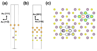
Two epitaxial configurations are considered, as shown in Fig. 3. In {111} epitaxy (Fig. 3(a) and top right of 3(c)), Au (111) plane is lattice matched onto the MoS2. In Fig. 3(c), the green circles are the gold atoms in the first layer that lie exactly on top of the Sulfur atoms. The green dashed lines define the unit cell. The gold atoms in the second and third layer are projected onto the growth plane and are represented by the blue and red circles, respectively. The stacking of gold layers follows the “ABCABC…” sequence to be consistent with the Face Center Cubic (FCC) structure, with the “B” sites residing on top of the Mo atoms. (The “ACBACB” sequence is slightly higher in energy (about 0.01 eV/unit cell) than the “ABC” configuration. Thus we take the “ABC” sequence for {111} epitaxy, though both structures have been realized experimentally Jacobs et al. (1966).) In {001} epitaxy, the Au (001) plane is lattice matched onto the MoS2 (Fig. 3(b) and bottom left of 3(c)). In the top view, the gold atoms in the first layer are represented by grey circles. The grey dashed line defines the unit cell. The black circles are the projections of the gold atoms in the second layer. The stacking sequence follows “A′B′A′B′…” sequence. We constructed models for both configurations with the number of Au layers vary from 3 to 30. A 14141 Monkhorst-Pack k-point grid is used to sample the Brillioun zone for {111} epitaxy. In {001} epitaxy, a 1381 Monkhorst-Pack k-point grid is used. These structures are relaxed until the maximum Hellmann-Feynman force on any atom is below 0.01 eV/Å.
The DFT calculated lattice structures and elastic constants of bulk Au and monolayer MoS2 are in good agreement with previous studies (details in the Supplementary Materials). The calculated elastic constants are used for the parameters and . The calculated lattice structures are used to determine , , and .
Within the density functional theory approach, the change in energy associated with our synthesis path can be written (neglecting the slip energy):
| (6) |
with the total energy of the lattice matched slab including one MoS2 layer and layers of Au (in each unit cell). is the energy per layer of bulk unstrained Au and is the energy of the monolayer MoS2. We fit the results of DFT calculations to both Eqn. (1) and the equilibrium strains (with more weight on the energy fit side) to determine the parameters remaining in that expression. (These turn out to be linear combinations of the surface and interfacial energy terms. See the Supplemental Material for more details about fitting processes.)
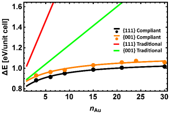
Figure 4 compares the ’s for {111} and {001} oriented epitaxial growth. The results of DFT calculations are displayed, as is their fit to Eqn. (1). It is apparent that the elasticity theory based model does an excellent job of describing the DFT results, and can be used to extrapolate behavior to thicker films. In addition, Fig. 4 displays the predictions assuming a rigid substrate (traditional epitaxy), and the interfacial energies and stresses computed within the model.
Examination of the Fig. 4 reveals two important points. First and foremost, within the compliant substrate epitaxial model, for all considered numbers of Au layers, {111} epitaxy is energetically favored over {001} oriented epitaxy. However, the energy difference is not too large, and one might expect to see both orientations, with the {111} orientation favored. Thus the compliant substrate epitaxy model is able to explain the experimental observations of {111} oriented epitaxy of Au on MoS2.
Second, the variation of with thickness is sublinear in the case of compliant substrate epitaxy. This sublinear behavior originates in the fact that the strain energy per layer is decreasing as the film thickness increases. As the film gets thicker, it becomes elastically more stiff, and the first layer of the substrate is forced to deform to a greater extent. Eventually, when the film is infinitely thick, only the first substrate layer deforms, and the elastic energy saturates at a constant. To our knowledge, this reduction in strain energy of the film with increasing film thickness is a unique feature of compliant substrate epitaxy.
These observations suggest the following understanding of the preferred orientation of the films. First, the relaxation of the substrate is not expected to change the sign of the strain energy difference between {111} and {001} oriented films. Based on strain energy alone, one would still expect {001} oriented films, even for a compliant substrate. This implies that the sum of the {111} Au surface and Au/MoS2 interfacial energies is less than the sum of the {001} Au surface and Au/MoS2 interfacial energies in the compliant substrate epitaxy, a fact consistent with our fitted parameters (See Supplemental Material). So in this instance, the properties of the interfaces and the surfaces dictate the orientation of the growing film.
This observation is not, in itself surprising. When the films are nucleated, they are very thin, and the surfaces and interfaces can make a significant contribution to . However, the persistence of the orientation preference with increasing film thickness is remarkable. Typically, one expects that the strain energy difference would become the dominant term in , and the favored orientation would change to {001} for thicker films. This is where the compliance of the substrate becomes important. Since the substrate is compliant, the strain energy of the Au film no longer scales with the volume of the Au film. Instead, it monotonically decreases with increasing film thickness, enabling the interfacial and surface contributions to the energy to dictate the stability of the two orientations for all film thicknesses.
The model presented here is the not first proposed that exploits a compliant substrate. As early as 1991, Lo suggested that the quality of some epitaxial films could be improved by employing a compliant substrate Lo (1991). Such a substrate would enable relaxation of the film at the expense of the substrate, but had the potential to increase the quality of the epitaxial film. Lo suggested that such substrates could be produced using standard lithographic methods. Later, Jesser et al. proposed that a compliant substrate might be developed by introducing a subsurface twist boundary Jesser et al. (1999). Here, it is noted that layered materials with VDW bonding between them form naturally compliant substrates for epitaxial growth Alaskar et al. (2014). Moreover, the VDW bonding, while enabling lateral slip of the substrate, will resist buckling of the film, and thereby help to improve its quality. Though we have examined Au on MoS2 in detail, the idea is quite general, and should apply to other systems as well.
Note that this version of compliant substrate epitaxy is different from the so-called van der Waals epitaxy Koma (1992). In the compliant substrate epitaxy model, lattice registry is maintained across the interface, and a degree of covalent bonding between the substrate and the film is allowed. In contrast, in the van der Waals epitaxy case, one does not expect lattice registry between the film and the substrate.
We note that compliant substrate epitaxy may have interesting implications for strain engineering and processing of thin films. Consider the strain field near a small Au island in the early stages of the film growth. The MoS2 under the island will be strain in compression. This will naturally be accommodated by a tensile strain surrounding the island. Therefore, it might be possible to engineer the positions of the Au nuclei so as to induce a desired strain pattern into the first layer of the MoS2 substrate. Moreover, it might be possible to use the epitaxial binding as a means of freeing and manipulating the top layer of the MoS2, just as was demonstrated for C nanotubes He et al. (2014). Finally, the fact that under conditions of compliant substrate epitaxy, surface and interfacial energies can dictate the orientations of thick films raises the possibility of using surface chemistry and/or surfactants to engineer the relative stability of different film orientations within the same materials system.
In conclusion, the epitaxial growth of Au on MoS2 is studied using a combination of elasticity and density functional theories. It is shown that the compliance of the substrate in conjunction with the relative surface and interfacial energies and strain energies stabilize the {111} growth orientation despite the large lattice mismatch. This system is thus an example of compliant substrate epitaxy.
Acknowledgements.
This work was supported by the Director, Office of Science, Office of Basic Energy Sciences, Division of Materials Sciences and Engineering, of the U.S. Department of Energy under Contract No. DE-AC02-05CH11231.References
- Radisavljevic et al. (2011) B. Radisavljevic, A. Radenovic, J. Brivio, V. Giacometti, and A. Kis, Nature nanotechnology 6, 147 (2011).
- Jacobs and Stowell (1965) M. H. Jacobs and M. J. Stowell, Philosophical Magazine 11, 591 (1965).
- Jesser and KuhlmannWilsdorf (1967) W. A. Jesser and D. KuhlmannWilsdorf, Journal of Applied Physics 38, 5128 (1967).
- Honjo and Yagi (1969) G. Honjo and K. Yagi, Journal of Vacuum Science and Technology 6, 576 (1969).
- Pashley et al. (1964) D. W. Pashley, M. J. Stowell, M. H. Jacobs, and T. J. Law, Philosophical Magazine 10, 127 (1964).
- Jacobs et al. (1966) M. H. Jacobs, D. W. Pashley, and M. J. Stowell, Philosophical Magazine 13, 129 (1966).
- Jesser and Kuhlmann-Wilsdorf (1967) W. A. Jesser and D. Kuhlmann-Wilsdorf, Phys. Stat. Sol. 19, 95 (1967).
- Grimme (2006) S. Grimme, Journal of Computational Chemistry 27, 1787 (2006), ISSN 1096-987X, URL http://dx.doi.org/10.1002/jcc.20495.
- Kresse and Hafner (1993) G. Kresse and J. Hafner, Phys. Rev. B 47, 558 (1993), URL http://link.aps.org/doi/10.1103/PhysRevB.47.558.
- Perdew et al. (1996) J. P. Perdew, K. Burke, and M. Ernzerhof, Phys. Rev. Lett. 77, 3865 (1996), URL http://link.aps.org/doi/10.1103/PhysRevLett.77.3865.
- Kresse and Joubert (1999) G. Kresse and D. Joubert, Phys. Rev. B 59, 1758 (1999), URL http://link.aps.org/doi/10.1103/PhysRevB.59.1758.
- Lo (1991) Y. H. Lo, Applied Physics Letters 59, 2311 (1991).
- Jesser et al. (1999) W. A. Jesser, J. H. van der Merwe, and P. M. Stoop, Journal of Applied Physics 85, 2129 (1999).
- Alaskar et al. (2014) During peer review the authors were made aware that Alaskar et al. discuss the concept of compliant substrate epitaxy in reference to growth on graphene, though they ultimately apply a different model to their experimental data. For details, see: Y. Alaskar, S. Arafin, D. Wickramaratne, M. A. Zurbuchen, L. He, J. McKay, Q. Lin, M. S. Goorsky, R. K. Lake, and K. L. Wang, Advanced Functional Materials 24, 6629 (2014), ISSN 1616-3028, URL http://dx.doi.org/10.1002/adfm.201400960.
- Koma (1992) A. Koma, Thin Solid Films 216, 72 (1992).
- He et al. (2014) Y. He, D. Li, T. Li, X. Lin, J. Zhang, Y. Wei, P. Liu, L. Zhang, J. Wang, Q. Li, et al., Nano Research 7, 981 (2014), ISSN 1998-0124, URL http://dx.doi.org/10.1007/s12274-014-0460-9.