∎
Royal Institute of Technology, 100 44 Stockholm, Sweden
22email: brosse@mech.kth.se
Experimental study of a three dimensional cylinder-filament system
Abstract
This experimental study reports on the behavior of a filament attached to the rear of a three-dimensional cylinder. The axis of the cylinder is placed normal to a uniform incoming flow and the filament is free to move in the cylinder wake. The mean position of the filament is studied as a function of the filament length . It is found that for long (, where is the cylinder diameter) and short () filaments the mean position of the filament tends to align with the incoming flow, whereas for intermediate filament lengths () the filament lies down on the cylinder and tends to align with the cylinder axis. The underlying mechanism of the bifurcations are discussed and related to buckling and inverted-pendulum-like instabilities.
Keywords:
Wake Symmetry breaking Fluid-Structure interaction1 Introduction
Many animals, plants and seeds have appendages or protrusions that through a passive interaction with the surrounding fluid can aid locomotion. The underlying physical mechanisms responsible for such positive fluid-structure interaction can be isolated using simple body-appendage configurations. For example, two-dimensional numerical (Xu et al, 1990) and experimental (Cimbala and Chen, 1994) studies have reported on a cylinder free to rotate around its axis with a rigid splitter plate attached to it. When this system is placed in a uniform incoming flow, it is found that for long lengths of the splitter plate, the mean position of the splitter plate is symmetric - i.e. it aligns with the incoming flow - whereas for short lengths, the symmetry is broken, i.e. the mean position of the splitter plate will form an angle with the incoming flow. More recently, Bagheri et al (2012) studied through two-dimensional numerical simulations the behavior of a single elastic filament hinged on the rear of a fixed bluff body and placed in a uniform incoming flow. They also found a symmetry-breaking for sufficiently short filament lengths and reported on the induced lift/side force acting on the cylinder-filament system. More specifically, they showed that for a long filament (symmetric position), the mean lift force and torque acting on the cylinder is zero, whereas when the filament length is reduced below two cylinder diameters, a significant mean lift force/torque acting on the cylinder is generated. Even more recently, Lacis et al (2014) performed numerical simulations of a free-falling circular cylinder with a splitter plate and found that for short splitter plates the body drifts – as a consequence of symmetry breaking – either to the left or right. They also proposed a theoretical model - referred to as the inverted-pendulum-like (IPL) model - that provides quantitative predictions of the critical filament length of the symmetry breaking. In this model, the pressure in the recirculation zone behind the bluff body acts as a destabilizing force and is responsible for the symmetry breaking. Lacis et al (2014) also found numerically the IPL instability in a three-dimensional configuration consisting of a sphere (free to rotate and drift) with an attached thin elliptic-shaped sheet. It was confirmed that the mean position of the short sheet forms an angle with the incoming flow and thus drifts. In summary, previous studies have shown that flexible/rigid appendages can be used to passively control the flow, for example by modifying the trajectory of falling bodies such as cylinders (Horowitz and Williamson, 2010), spheres or disks (Ern et al, 2012). The aim of the present study is to experimentally investigate the behavior of a three-dimensional cylinder with a filament attached to its rear and placed in a uniform flow. To the best knowledge of the authors, this configuration has not been investigated previously, as earlier work has either been two-dimensional or numerical. The physical problem depends on seven dimensional parameters: the cylinder diameter , the length of the filament , the fluid density and filament density , the bending stiffness of the filament , the free-stream velocity and the kinematic viscosity . Four non-dimensional parameters may then be introduced, namely, the length ratio , the density ratio , the Reynolds number and the bending ratio . In the present study, two free-stream velocities ( and ) are investigated, which results in two configurations (, ) and (, ). For each of these configurations, the length ratio is varied , but the density ratio is kept fixed ().
2 Method
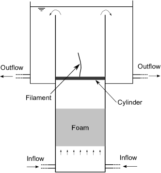
The experiments have been carried out in a vertical water tunnel; a schematic of the experiment is presented in figure 1. The whole apparatus is about m high, 1 m wide and 0.4 m deep. The dimensions of the test section are 20.5 cm wide, 39.7 cm deep, 68 cm high. Below the test section a 40 cm long slab of foam is placed in order to homogenize the flow. The vertical flow of water is generated with a pump with typical flow rate of 0.76 L.s-1, which corresponds to an upward fluid velocity cm.s-1 in the test section. The cylinder is made from a plexiglass tube with a diameter mm and length of cm. This cylinder is placed in the test section with its axis of symmetry normal to the incoming flow. A hole is drilled in the cylinder through which a thread made from silk is inserted. The flow inside the channel was previously measured by Bellani (2005) with ultrasonic velocity profiler (UVP). At the position of the cylinder – 20 cm above the foam – fluid velocity profiles for were measured along the direction; the fluid velocity was found to vary within over of the center of the channel, the turbulence intensity of was found to be .
The position of the filament can be defined by two angles of deflection, one from the front and one from the side - called and , respectively. These two angles are shown schematically in figures 2(a) and 3(a). As the shape of the filament is not a straight line but can be curved it can be noted that the two angles of deflection and do not take into account the shape of the filament. As a consequence, the two angles give only partial information regarding the position of the filament, nevertheless and indicate the behavior of the filament regarding the symmetry breaking and the lie down behavior that this paper focuses on. In order to measure the position of the filament, the cylinder is photographed with two perpendicular cameras ( pixels), one from the front and one from the side. The conversion factor is found to be 5 pixels per mm corresponding to an accuracy of mm in the determination of the filament position. For each length of the filament a series of grey scale images are recorded; in total seventeen filament lengths are recorded between . For each series an acquiring rate of 2 Hz and an exposure time of 10 ms was used; for the Reynolds number the recording time is 4 minutes and 10 seconds resulting in 500 images and for the recording time is 8 minutes and 20 seconds resulting in 1000 images for each measured filament length. The greyscale images are then converted to black and white images in order to detect the filament position. The angles of deflection are calculated as the angles between the vertical and the line formed by the filament attachment point to the cylinder and the endpoint of the filament (positive angles are defined in the clockwise direction). To obtain the mean angles of deflection, the angles for the entire measurement series (500 and 1000 images for and respectively) are averaged in time and the absolute value of this mean is then taken to give the mean angles of deflection and .
3 Filament behavior
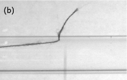
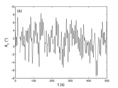
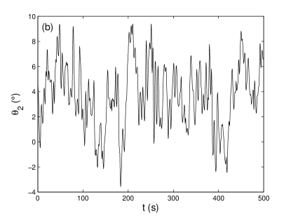
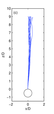
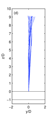
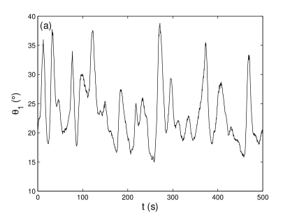
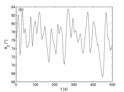
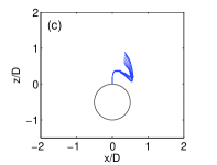
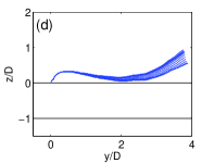
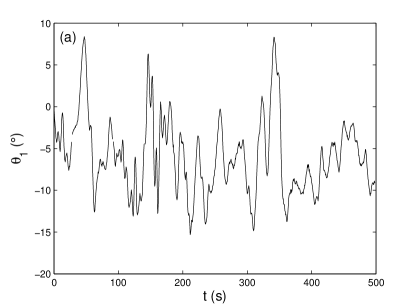
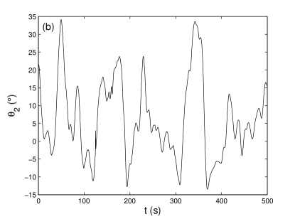
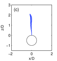
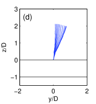
In this section, the time evolution of the filament position in the cylinder wake are shown, followed by a study of the mean position of the filament as a function of its length. Figures 4, 5 and 6 show the time evolution of the angles of deflection, and and the corresponding filament positions at different times for three filament lengths, namely, , and (). For the longest length shown in figure 4, the angles and oscillate around a value close to , indicating that the filament is almost vertical (figures 4a and 4b). This can also be seen in the filament positions presented in figure 4(c) for the front view and in figure 4(d) for the side view. Figure 5 shows that for the intermediate filament length, , the angle oscillates around a value close to and the angle oscillates around (figures 5a and 5b). This indicates that the filament is lying down as can be observed in figures 5(c) and 5(d). Note that for this situation, the detectable part of the filament from the front view is reduced; however, the angle clearly shows the collapse of the filament towards the cylinder surface. For the shortest filament , the angles and are close to (figures 6a and 6b) indicating that the filament is again almost vertical. This can also be observed in the filament position in figure 6(c) and 6(d).
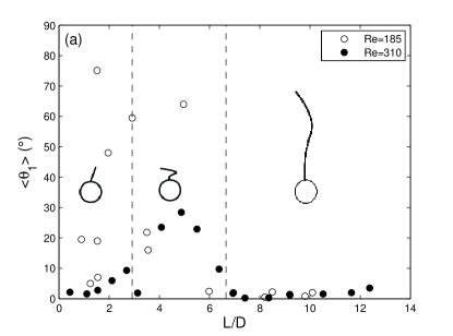
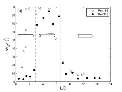
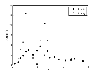
The average angles of deflection and are shown in figures 7(a) and 7(b) as a function of for the two Reynolds numbers under investigation. For filaments longer than , and are smaller than and , respectively. This indicates that the mean position of the filament is nearly vertical from the front view - i.e. aligned with the incoming flow - and slightly tilted from the side view (schematically shown as inset frames in figure 7). Figure 8 presents the standard deviation of the angles and as a function of the filament length for . For these long filament lengths the standard deviation of the filament oscillations are below for both angles and increase close to the bifurcation.
When the filament length is reduced below a critical value, , a first bifurcation takes place as the angle increases dramatically to reach values higher than . The angle also increases at this bifurcation. Thus, in this regime the filament tends to collapse (i.e. fall down) on the cylinder and align with the axis of symmetry of the cylinder (normal to the incoming flow) as schematically shown in figure 7. Once the filament collapses on one side, it does not flip to the other side. Out of 10 experiments we performed for this particular configuration, the filament fell down to the left twice and to the right 8 times. In perfect symmetric conditions, one would expect an equal probability for the filament to fall to right and left, however further samples and statistical analysis are required to confirm this. For these intermediary filament lengths the standard deviation of the angle varies between and ; the standard deviation of the angle varies between and (figure 8). The evolution of these amplitudes with the filament length are non-monotonic in this range.
Finally a second bifurcation takes place at for and at for ; the value of the mean angle is smaller than (figure 7a) and the angle is reduced from values higher than to values lower than (figure 7b). This indicates that the mean position of the filament is still tilted, but tends to realign with the incoming flow as shown schematically in figure 7. For these short filament lengths the standard deviation of and decrease from respectively and to for both angles (figure 8), indicating that the amplitudes of the filament oscillations decrease with the filament length.
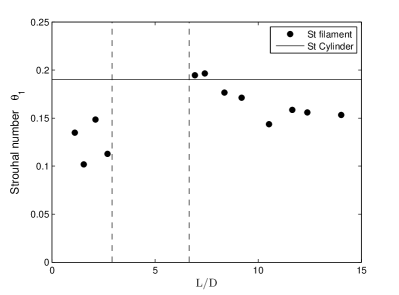
Concerning the frequencies of the filament oscillations, it can be observed from figures 4(a), 4(b), 5(a), 5(b), 6(a) and 6(b) that several distinct frequencies are contained in each signal. For no clear frequency seem to dominate. For on the other hand, the Strouhal number of the dominant frequency is plotted as a function of the filament length in figure 9 (for ). For long filament lengths, , the Strouhal number of is between and , which is close to the natural vortex shedding frequency of the cylinder wake (at , see e.g. Williamson (1996)). Thus, for the filament oscillation frequency seems to be somewhat synchronized with the vortex shedding in the cylinder wake. Note however that contains also other frequencies that are not shown here. For intermediary filament lengths no clear dominant frequency could be identified. Finally, for short filament length the Strouhal number of the filament oscillation frequency is between and and is significantly different from . The different dynamical regimes determined from the average angles seem thus to be reflected in the dominant time scale of .
We can also note some differences in the bifurcations between the two Reynolds numbers studied here, namely and . As previously indicated, the main marker of the bifurcations is the angle and it can be compared between the two Reynolds numbers on figure 7(b). For the higher Reynolds number, , the first bifurcation appears at and at for the second whereas for the bifurcations appear at a slightly different filament lengths; at and . The bifurcations seem also to be more sharp at compared to where it is more continuous. Despite these differences, it is clear that the same bifurcations are observed for both Reynolds numbers and these bifurcations seem to be robust in this range of Reynolds number.
4 Discussion
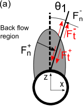
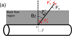
Although, further quantitative investigations are necessary for confirmation, we believe that it is likely that the bifurcations described above are related to a buckling instability and an IPL instability. At the Reynolds numbers considered in this study, the recirculation region (Williamson, 1996) can be characterized by its mean length, which decreases from 1.5 to 1 D when the Reynolds number increases from to (Silva et al, 2003; Nishioka and Sato, 1978; Park et al, 1998). Inside this recirculation region we can define a back-flow region where the fluid velocity is opposite to the streamwise direction. This back-flow region can be modelled as an ellipse in the -plane (Lacis et al, 2014) and in the three-dimensional case this ellipse is extended in the direction. The shape of the back-flow region is schematically shown in figure 2(a) for the -plane and in figure 3(a) for the -plane. The behaviour of the filament can be related to this mean flow and may be attributed to two different types of instabilities.
The first instability is a similar mechanism as the two dimensional IPL instability (Lacis et al, 2014), i.e. the pressure force in the back-flow region behind the cylinder, exerts a net normal force on the filament, which pushes the filament away from the symmetric vertical position. The part of the filament outside the back-flow-region on the other hand, experiences a net normal restoring force , which pushes the filament towards the straight vertical position. As shown schematically in figure 2(a), the final position of the filament is due to the competition between these two forces, which for sufficiently short filaments results in a tilted mean position with respect to the direction of the incoming flow. The key difference to the work of Lacis et al (2014) is that in the present three-dimensional case, we have observed that the filament falls down on the cylinder in the vertical -plane containing the cylinder axis (in contrast to the -plane). In the -plane, the back-flow region has on average a rectangular form (in contrast to the elliptic shape in the -plane). As a consequence, the restoring normal force outside the back-flow region becomes increasingly small as increases and once the straight position of the filament is unstable no other force can prevent the filament to lie down on the cylinder. Although, physically an IPL-type of instability could be responsible for the first bifurcation, the critical value of filament length near is much larger than the critical values () reported in previous work on the IPL instability and also much larger than the length of the recirculation region which is D at these Reynolds numbers (Silva et al, 2003; Nishioka and Sato, 1978; Park et al, 1998).
The second instability that could induce the collapse of the filament onto the cylinder surface in the -plane is a buckling-type of mechanism. This instability arises out of the competition between the tangential forces and (shown schematically in figure 3a) on the filament inside and outside the back-flow region. As a consequence of these forces, part of the filament outside the back-flow region is stretched by the flow and the part of the filament inside the back-flow region is compressed. If the filament is sufficiently short, the compressive force will dominate, which in turn may result in a buckling instability of the filament. For the second bifurcation at , where the filament tends to realign with the flow, the filament is unlikely to undergo a buckling instability as the critical load for the onset of the buckling instability scales as .
The above discussion suggests that the first bifurcation at could be dominated by a buckling-type of instability. Further studies, in particular by estimating the loads acting on the filament, are necessary to confirm this statement and to quantitatively assess the mechanisms underlying the bifurcations.
5 Conclusions
This experimental study has focused on the behavior of a filament attached to the rear of a three dimensional circular cylinder placed in a uniform incoming flow. The length of the filament was varied and for each length the mean position of the filament was determined. For lengths, longer than the mean position of the filament is nearly aligned with the incoming flow. For intermediate lengths, , it was found that the filament lies down on the cylinder, i.e. the mean position of the filament is aligned with the axis of the cylinder. Finally for shorter than the mean position is tilted in both directions with respect to the incoming flow. To the best of our knowledge these two bifurcations of a flexible filament in wake flows have not been observed nor reported in earlier work.
References
- Bagheri et al (2012) Bagheri S, Mazzino A, Bottaro A (2012) Spontaneous symmetry breaking of a hinged flapping filament generates lift. Phys Rev Lett 109:154,502
- Bellani (2005) Bellani G (2005) Design and evaluation of a novel apparatus for sedimentation studies. Master’s thesis, Seconda Facoltà di Ingegneria, Università di Bologna
- Cimbala and Chen (1994) Cimbala JM, Chen KT (1994) Supercritical Reynolds number experiments on a freely rotatable cylinder/splitter plate body. Phys Fluids 6(7):2440–2445
- Ern et al (2012) Ern P, Risso F, Fabre D, Magnaudet J (2012) Wake-induced oscillatory paths of bodies freely rising or falling in fluids. Annu Rev Fluid Mech 44(1):97–121
- Horowitz and Williamson (2010) Horowitz M, Williamson CHK (2010) Vortex-induced vibration of a rising and falling cylinder. J Fluid Mech 662:352–383
- Lacis et al (2014) Lacis U, Brosse N, Ingremeau F, Mazzino A, Lundell F, Kellay H, Bagheri S (2014) Passive appendages generate locomotion through symmetry breaking. Nat Commun 5:6310
- Nishioka and Sato (1978) Nishioka M, Sato H (1978) Mechanism of determination of the shedding frequency of vortices behind a cylinder at low reynolds numbers. J Fluid Mech 89:49–60
- Park et al (1998) Park J, Kwon K, Choi H (1998) Numerical solutions of flow past a circular cylinder at reynolds numbers up to 160. KSME Int J 12(6):1200–1205
- Silva et al (2003) Silva ALE, Silveira-Neto A, Damasceno J (2003) Numerical simulation of two-dimensional flows over a circular cylinder using the immersed boundary method. J Comput Physics 189(2):351–370
- Williamson (1996) Williamson CHK (1996) Vortex dynamics in the cylinder wake. Annu Rev Fluid Mech 28:477–539
- Xu et al (1990) Xu JC, Sen M, Gad-el Hak M (1990) Low-Reynolds number flow over a rotatable cylinder-splitter plate body. Phys Fluids A: Fluid Dynamics 2(11):1925–1927