11email: t.n.clark@mdx.ac.uk
Meta-Packages: Painless Domain Specific Languages
Abstract
Domain Specific Languages are used to provide a tailored modelling notation for a specific application domain. There are currently two main approaches to DSLs: standard notations that are tailored by adding simple properties; new notations that are designed from scratch. There are problems with both of these approaches which can be addressed by providing access to a small meta-language based on packages and classes. A meta-modelling approach based on meta-packages allows a wide range of DSLs to be defined in a standard way. The DSLs can be processed using standard object-based extension at the meta-level and existing tooling can easily be defined to adapt to the new languages. This paper introduces the concept of meta-packages and provides a simple example.
1 Introduction
The aim of any notation for software system design must be to faithfully capture the structure and behaviour of the proposed system. The aim of any tooling that supports such a notation must be that it is reliable and provides useful functionality. What kind of functionality? Certainly, the notation must be a good vehicle for communication - other people must be able to understand your ideas expressed in the notation. However, communication is not sufficient; the notation must support other useful tasks that contribute to the development of a system. A design notation must allow a tool to provide feedback on whether the system is likely to work, perhaps even allow a tool to animate parts of the design. In addition, it should be possible to generate parts of a system from its design.
In recent years there has been interest in Model Driven Architecture [11], Software Factories [12], tool definition languages and Domain Specific Languages. All of these initiatives aim to provide design notations that achieve the aims outlined above. These technologies fall broadly into two categories: standard vs. extensible languages.
1.1 Standard Modelling Notations
The design notation is standard. UML 2.X is an example of this category whereby the notation is standard with some limited scope for extension points. In the case of UML there is a very large number of different types of design element. Each type of element can be stereotyped by defining properties and changing the iconization. This is similar to annotations recently added to Java. The advantages of this approach are that the design notation is completely standard in terms of how it is presented to the user, therefore tools mature quickly, the expertise required to use the technology is relatively low, and information is interoperable between tools. The disadvantage is that the notation designers must preempt all the element types that will be required, leading to notational bloat, and the scope for notational extension is very limited.
1.2 User Extensible Notations
The design notation is user-defined. There are a number of technologies including Microsoft Visual Studio DSL tools [8], GMF [2] and MetaEdit+ [1] that allow a user to define new notation. The extent to which the notation can be extended differs between technologies: some tooling limits the definition through wizards and some allows arbitrary extension through program-level interfaces. In most cases, the underlying model for the design notation (the so-called meta-model) is defined by the user and therefore the data representation is tailored to the application domain. An advantage of this approach is that both the notation and underlying data representation are a good fit for the application domain, therefore tooling can take advantage of this by supporting the use of the notation. The main disadvantages of this approach are that the skill levels required to work with technology are relatively high and that the graphical tooling must be developed (even model-based) for each new language.
1.3 The Best of Both Worlds
Is it possible to achieve the advantages of each approach without the disadvantages? Analysis of the use of many design notations leads to the conclusion that many features recur while others differ. In most cases there are package-like and class-like elements with association-like relationships between them. Variations occur due to different categories of these basic features with their own specific properties.
This paper describes an approach to domain specific languages that allows arbitrary extension of a small collection of underlying modelling concepts via access to a self-describing meta-model. It shows that by adding the notion of meta-packages to the meta-language, tooling can be designed that offers domain specific languages without wholesale definition of a new language (such as that required by EMF and GMF). The need for DSL tooling is discussed further by Fowler [10].The result is an extensible modelling notation that reuses the same tooling. The use of meta-package based technology does not require skills in complete language definition and is not limited to the simple property-based extensions of the standards based approach described above. In addition, by extending the notion of a package slightly, many new language features can be added.
Meta-packages are implemented in XMF-Mosaic and have been used on a number of projects including generating code for telecomms applications [3, 4, 5, 6, 7]. The screen-shots and code in this paper are taken from a tutorial example that is implemented in XMF-Mosaic. The book [14] provides a good introduction to meta-modelling concepts.
The rest of this paper is structured as follows: section 2 provides the motivation for meta-packages using a simple example; section 3 defines meta-packages and how associated tooling accommodates them; section 4 implements the example DSL using meta-packages; finally, section 5 reviews meta-packages, describes some extensions and discusses related systems.
2 Example Application
Design notations should support the generation of source code where this is sensible. The generation of source code from standard modelling notations raises a problem. One of the merits of a modelling notation is that it abstracts away from implementation details; however, implementation details are required in order to generate the code. In effect, an arbitrary number of sub-categories of modelling element needs to be identified and represented in the design. Each category can be defined in terms of properties, structure or behaviour.
Standard modelling notations often allow categories to be defined using simple properties. However, this is not addressing the real issue which is to be able to define new categories of modelling element with their own structure and behaviour. Meta-packages support the definition of new element categories by allowing a standard modelling language to be extended at the meta-level. This section motivates the definition of meta-packages using a simple example.
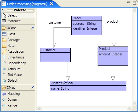
Java has recently been extended with annotations which can be used to add properties to standard Java program elements such as classes. The motivation for annotations has been the need to mark-up Java components with static information that can be used by tooling. An example use of annotations is in the implementation of enterprise information systems where Java class use annotations to define a mapping to relational database tables. For example the simple model defined in figure 1 may give rise the to following Java code:
@Entity
@Table(name="ORDER_TABLE")
public class Order {

  private int id;
  private String address;

  @Id
  @Column(name="ORDER_ID")
  public int getId() {
    return id;
  }
  public void setId(int id) {
    this.id = id;
  }

  @Column(name="SHIPPING_ADDRESS")
  public String getAddress() {
    return address;
  }
  public void setAddress(String address) {
    this.address = address;
  }
}
in which instances of the class Order are to be persisted in a relational database as rows in the table named ORDER_TABLE with columns ORDER_ID and SHIPPING_ADDRESS. The primary key of this table is ORDER_ID.
The tool used to represent the model in figure 1 is standard since it provides tools in the palette to create basic modelling elements: Package, Class, Attribute etc. Given a model using this tool, there is no way to distinguish between those model element that will become entity beans and those that will become basic Java classes.
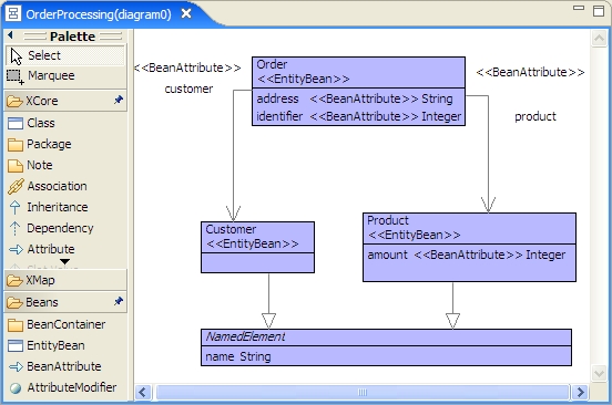
Figure 2 shows a tool that provides a new category of modelling element: Beans. The model for the order processing system now includes two different categories of modelling element: Classes and Attributes, EntityBeans and BeanAttributes. It is now possible to distinguish between the elements in terms of code generation. In addition, EntityBean will have a property that defines the name of the relational database table used to represent its instances.
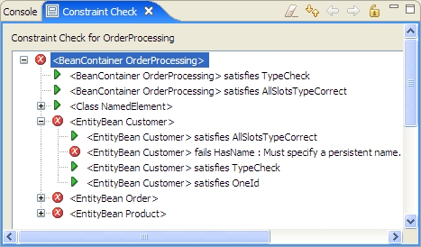
In addition to defining new modelling entities, a DSL has semantics. Part of the semantics of a language are the rules that govern correct model formation. These are expressed at the meta-package level, for example an EntityBean is correctly formed when it has at most one bean attribute that is designated as an id (the primary key in the table). Figure 3 shows the result of running the well-formedness checks for the meta-package over the instance shown in figure 2. Leaves of the tree are constraints that have been applied to the model elements. Triangles represent constraints that are satisfied. Crosses are constraints that have failed. Therefore, in the example model the Customer element has OneId (a single attribute designated as a primary key) but does not specify a persistent name (a table in the database).
3 Meta-Packages
Meta-packages are a way of defining semantically rich DSLs without having to specify associated tooling. The idea is that there is a single basic meta-package that defines a language. The concepts in the base meta-package can be extended to produce new meta-packages. Each meta-package is a language and tooling is written against the base meta-package. Since all new meta-packages are extensions of the base, the existing tooling will work with any new language. Since languages are written at the meta-level, executable meta-modelling allows any new language to have a rich semantics.
This section defines meta-packages and is structured as follows: section 3.1 defines the base meta-package called XCore; section 3.2 defines a tool model for languages over XCore; section 3.3 defines a model for tool diagrams; section 3.4 defines a model for the display elements on diagrams; finally, section 3.5 defines mappings that ensure the diagrams and model elements are synchronized in the tools.
3.1 XCore
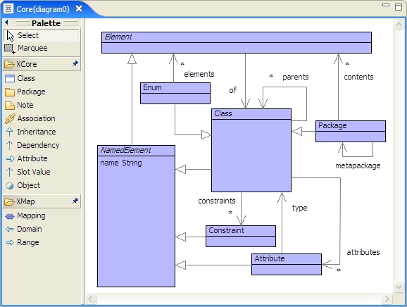
Meta-packages are defined in a meta-circular language defined in figure 4. This language is part of the basic package, called XCore, of the XMF-Mosaic modelling tool. In XMF-Mosaic, everything is an element. Classes are elements with names, constraints, attributes and parents. Note that every element has a type (of) which is a class. A Package is a class that contains elements and which has a meta-package. The idea of the meta-package association is that each element contained by a package is of some class contained by its meta-package. By default, the meta-package of all packages is XCore.
The semantics of XCore is defined using a collection of constraints. Since XCore is self defining these constraints are defines with respect to XCore itself. The following is an example which states that all elements of an enumerated type must be instances of that type and no other instances exist:
context Enum
  elements->forAll(e | e.of = self)
context Element
  of.of = Enum implies
    of.elements->includes(self)
XCore supports executable meta-modelling via XMF. The following operations are used in the rest of this paper:
context Class
  @Operation allParents():Set(Class)
    parents->iterate(p P = Set{} |
      P + p.allParents())
  end
context Package
  @Operation modellingElements():Set(Class)
    elements->select(e |
      e.isKindOf(Class))
  end
context Element
  @Operation tag(expected:Class):String
    if of = expected
    then ""
    else of.name
    end
  end
3.2 Tools
Modelling in XCore-based languages is supported by tooling. Figure 4 shows an example of a modelling tool that consists of a palette on the left-hand side and a diagram containing modelling elements on the right. The palette contains buttons for the modelling elements defined in the modelling language. The tool palette depends on the modelling language’s meta-package; however there is only one tool engine which is parameterized with respect to the meta-package.
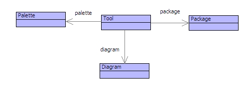
Figure 5 shows the key elements involved in defining a modelling tool. A tool associates a package of modelling elements, a diagram and a palette of button groups. Buttons are used to select creation modes. Events on the diagram modify diagram elements and events to the package modify modelling elements. Daemons on both the diagram and the package ensure that events from the model are propagated to the diagram and vice versa.
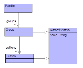
Figure 6 shows the structure of a tool palette. The palette consists of groups of buttons which are selected in order to determine the creation mode on a diagram. Each group corresponds to a meta-package. All packages have XCore as a meta-package by default and therefore have the XCore and XMap groups. If the meta-package of the package associated with a tool is P which inherits from XCore then the palette will have groups named XCore, XMap and P. This leads to the following constraint:
context Tool
  palette.groups.name =
  package.metaPackage.allParents().name
The buttons provided by each group are determined by the language elements defined in the meta-package. A modelling element is a sub-class of Package, Class or Attribute as defined in XCore. Therefore:
context Tool
  package.metaPackage.allParents()
    ->forAll(p |
      palette.groups
        ->exists(g |
           g.name = p.name and
             p.modellingElements().name =
               g.buttons.name))
3.3 Diagrams
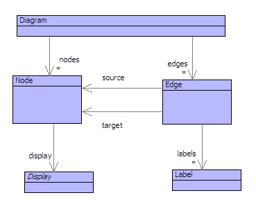
Each tool manages a diagram that consists of nodes and edges. Each node has a display that is used to render the node on the diagram. Each edge has a source and a target node and a collection of labels. The diagram model is shown in figure 7. The tool requires that the diagram is always synchronized with the package. Therefore the following constraint must always hold:
context Tool
  package.classes()->size =
  diagram.nodes()->size
The constraint on edges is less easy to define since attributes may be shown on a diagram within classes or as edges. In addition, inheritance is shown as edges. To make matters more complex the types of attributes and the target of inheritance edges may be imported from other packages.
3.4 Displays
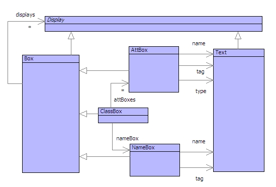
Figure 8 shows some of the display types that can be used to render nodes on diagrams. Two basic types of display are shown: boxes and text. Package-based diagrams use specializations of these display types to render classes. A class box consists of a name box and several attribute boxes. Note that attBoxes and nameBox are derived attributes since they are just specifically identified components of the displays. Both attrbute boxes and name boxes have some text for the name of the element. They also both have a tag which is used to identify the meta-type of the element if it not Class or Attribute respectively. An attribute box has an additional text field for the type of the attribute.
3.5 Mappings
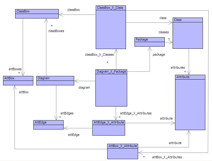
Diagram-model synchronization is handled by a collection of mappings associated with a tool. Figure 9 shows the mapping model for package diagrams. A mapping has the form A_X_B which associates instances of A with instances of B. Each mapping class has a constraint that defines the synchronization requirements. Many of these constraints state commutative properties of the model. For example:
context Tool
  mapping.package = package and
  mapping.diagram = diagram
Each of the mappings inherit from a class OneToOne (not shown) which requires that all maplets are unique. A mapping instance can reference all of the elements in the domain and range of the mapping and also reference all of the associations (one of which is itself). The following constraints require the OneToOne mapping to have unique associations:
context OneToOne
  domain->forAll(d |
    range->exists(r1 r2 |
      map(d,r1) and map(d,r2)
        implies r1 = r2))

context OneToOne
  range->forAll(r |
    domain->exists(d1 d2 |
      map(d1,r) and map(d,r2)
        implies d1 = d2))
All of the classes in the package must be shown on the diagram and all class nodes on the diagram must correspond to some class in the package:
context Diagram_X_Package
  package.classes = classBox_X_Classes.class
context Diagram_X_Package
  diagram.classBoxes =
  classBox_X_Classes.classBox
All the attribute edges must be related and must correspond to an attribute. Note that not all attributes need to be shown as edges on the diagram:
context Diagram_X_Package
  attEdge_X_Attributes.attEdge =
  diagram.attEdges
context Diagram_X_Package
  attEdge_X_Attributes.attribute
    ->subSet(package.classes.attributes)
The name of a class on a diagram must always be synchronized with the name of the corresponding model element. If the element is directly an instance of class then its tag is empty otherwise the tag must be the name of the meta-type:
context ClassBox_X_Class
  classBox.name = class.name
context ClassBox_X_Class
  classBox.tag = class.tag
All of the attributes in a class box must correspond to some attribute of the associated class. However, the not all attributes need to be displayed in a class box:
context ClassBox_X_Class
  attBox_X_Attributes.attribute
  ->subSet(class.attributes)
context ClassBox_X_Class
  attBox_X_Attributes.attBox =
  classBox.attBoxes
Attribute boxes offer a name, a type and an optional meta-tag. The following constraints require that these are always synchronized (attribute edge tags are specified using similar constraints):
context AttBox_X_Attribute
  attribute.name = attBox.name
context AttBox_X_Attribute
  attribute.type.name = attBox.type
context AttBox_X_Attribute
  attribute.tag = attBox.tag
Finally, any attribute edges that are shown on the diagram must correspond to attributes. The source of the edge must be a class box that corresponds to the owner of the attribute and the target of the edge must be a class that corresponds to the type of the attribute. The predicate isClass is not defined but is satisfied isClass(b,c) when the box b is associated with the class c in the tool:
context AttEdge_X_Attribute
  isClass(attEdge.sourceBox,attribute.owner)
context AttEdge_X_Attribute
  isClass(attEdge.targetBox,attribute.type)
All of the attributes must be shown as either edges or in boxes:
context Diagram_X_Package
  package.classes.attributes =
    attEdge_X_Attributes.attribute +
    classBox_X_Classes.attBox_X_Attributes.attribute
Other constraints can be defined to require that an attribute edge cannot be shown as a boxed attribute.
4 A Bean DSL
The previous section has defined the meta-package relationship that allows new class-based DSLs to be defined by extending meta-concepts. Existing tooling mechanisms can accommodate the new DSLs without any new code being necessary. This section shows how a new language to support Beans for Enterprise Systems can be defined using the meta-package relationship. The result of the definition is a new tool as shown in figure 2.
This section is defined as follows: section 4.1 describes the abstract syntax for the DSL; section 4.2 describes how concrete syntax can be defined in a number of ways; section 4.3 describes well-formedness semantics for the DSL; section 4.4 defines how Java code is generated from the DSL.
4.1 Abstract Syntax
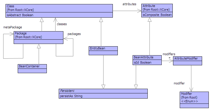
The first step in DSL definition is to define a new meta-package whose modelling concepts extend those of an existing meta-package. Figure 10 shows the definition of the package named Beans. The concepts are defined as follows:
-
BeanContainer
A bean container is a specialization of Package. The contents of a bean container may be entity beans and the class BeanContainer provides us with a container for bean specific constraints.
-
EntityBean
An entity bean is a class that has a persistsAs property that is used to name the relational database table used to contain all the instances of the class.
-
BeanAttribute
A bean attribute is a special type of attribute that names the column in the database table used to contain its values. A bean attribute can be tagged as being a primary key in the relational table by setting its isId attribute. A bean attribute may also require a Java accessor and updater. These properties are set via the attribute modifiers of the bean attribute.
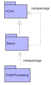
The Beans package must be designated as a meta-package. This is done by making it inherit from XCore as shown in figure 11. By default, a package inherits from an empty package and is therefore not a meta-package. By making a package inherits from a meta-package, the new package also becomes a meta-package.
The package OrderProcessing is to be written in the language defined by Beans. By default the meta-package of a new package is XCore. Figure 11 shows the meta-package of OrderProcessing has been changed to Beans. Note that the super-package of OrderProcessing has not been changed, so it stays as the default empty package and therefore OrderProcessing is not itself a meta-package.
4.2 Concrete Syntax
A DSL does not require a concrete syntax, but it is generally important for usability to have one. DSLs that are defined via meta-packages get a concrete diagram syntax for free. The tooling that is specified in section 3 detects the new modelling concepts and provides new palette buttons and labelling as appropriate.
In addition to diagram syntax for a language, textual syntax is often useful. XMF [13] has a text language for package definition that supports the declaration of meta-package information. This is exactly the same as the diagram tooling: the same text processing engine is used even though the language has changed via meta-package extension. The following shows how the OrderProcessing bean container can be defined using XMF package definition:
@Package OrderProcessing
  metaclass BeanContainer metapackage Beans
  @Class NamedElement isabstract
    @Attribute name : String end
  end
  @Class Order metaclass EntityBean
    @Attribute identifier
      metaclass BeanAttribute : Integer
    end
    @Attribute address
      metaclass BeanAttribute : String
    end
    @Attribute customer
      metaclass BeanAttribute : Customer
    end
    @Attribute product
      metaclass BeanAttribute : Product
    end
  end
  @Class Customer metaclass EntityBean
    extends NamedElement
  end
  @Class Product metaclass EntityBean
    extends NamedElement
    @Attribute amount
      metaclass BeanAttribute : Integer
    end
  end
end
A problem with the basic text definition shown above is that it does not provide support for setting the new meta-properties such as persistAs. These can be set independently, but it is much better if an entity can be defined as a modular unit. In addition, the above syntax exposes implementation details about the modelling concepts by requiring their meta-classes to be specified.
XMF supports extensible syntax via syntax-classes [13] which are normal classes that define grammars for processing text. This mechanism can be used to define a new concrete syntax for a DSL that translates into the basic definitions given above. The following is a DSL for beans that has been used to define the order processing system:
@BeanContainer OrderProcessing
  entity NamedElement
    name       (NAME)             : String
  end
  entity Order(ORDER_TABLE) [NamedElement]
    *identifier(ORDER_ID)         : Integer
    address    (SHIPPING_ADDRESS) : String
    customer   (CUSTOMER_REF)     : Customer
    product    (PRODUCT_REF)      : Product
  end
  entity Customer extends NamedElement
  entity Product extends NamedElement
    amount     (AMOUNT)           : Integer
  end
end
The example above hides all of the implementation detail. This is achieved by defining a new syntax class for BeanContainer as shown below:
@Class BeanContainer
  @Grammar
    BeanContainer ::= n = Name es = Entity* {
     [| let P = @Package <n>
                  metaclass BeanContainer
                  metapackage Beans end
        in <es->iterate(e x = [| P |] |
             [| P.add(<e>); <x> |])>
        end |]
    }.
    Entity ::=
     n = Name p = Persist s = Super as = Att* {
     [| let C = @Class <n>
                  metaclass EntityBean
                  extends <s>
                end
        in C.persistAs := <p.lift()>;
              <as->iterate(a x = [| C |] |
                [| <x>.add(<a>) |])>
           end
        |]
    }.
    Persist ::= ’(’ Name ’)’.
    Super ::= ’[’ Type ’]’.
    Att ::=
      i = IsId n = Name p = Persist ’:’ t = Type {
      [| let A = BeanAttribute(<n.lift()>,<t>)
         in A.persistAs := <p.lift()>
         end |]
    }.
  end
end
4.3 Constraint Checking
Constraint checking involves executable modelling (being able to attach executable predicate expressions to classes as shown in figure 4). Elements are well-formed when they satisfy all of the constraints defined by their class. In addition, containers, such as packages, are well formed when their contents are well-formed.
In order for a bean container to be well-formed, all of the persistent elements must specify a name that can be used in the relational database:
context Persistent
  @Constraint HasName
    persistAs <> ""
    fail "Must specify a persistent name."
  end
An entity bean is well formed when there is at most one bean attribute that designates a primary key:
context EntityBean
  @Constraint OneId
    not @Exists a1,a2 in attributes ->
          a1 <> a2 and
          a1.isId and
          a2.isId
        end
    fail "Cannot have multiple ids."
  end
4.4 Code Generation
Code generation involves a mapping from a model to source code. This is the essence of MDA in which UML models are translated to code. However, UML does not allow access to the meta-level and therefore the scope for extending the modelling language with sophisticated translation mechanisms is limited.
To translate from elements in figure 10 to the source code shown in section 2 we can also use executable meta-modelling technology. A code export operation is defined for each class that is to be translated. XMF provides code-template technology that makes it easy to generate code [13]. The following template:
@Java(out,leftMargin)
  class <n> {
  }
end
writes an empty class definition to the output channel, newlines tab to leftMargin. Within the Java code template all text is faithfully written to the output except for expressions delimited by < and >. Such expressions are evaluated and then written to the output channel. In the example above, the generated class will have a name that is the value of the variable n. Within expressions, the use of [ and ] delimiters switch back to literal code and nesting of [, ] and <,> is permitted.
Entity beans are translated to code as follows:
context EntityBean
  @Operation code(out:OutputChannel)
    @Java(out,7)
      @Entity
      @Table(name="<persistAs>")
      public class <name>  {
        <@For a in attributes
           when a.isKindOf(BeanAttribute) do
          [private <a.typeName()> <a.name>;]
         end;
         @For a in attributes
           when a.isKindOf(BeanAttribute) do
          a.code(out)
         end>
      }
    end
  end
Each bean attribute is translated to code as follows:
context BeanAttribute
  @Operation code(out:OutputChannel)
    let name = name.toString() then
        Name = name.upperCaseInitialLetter()
    in
      @Java(out,7)
        <if isId then [@Id] end>
        @Column(name="<persistAs>")
        <if self.canGet()
         then self.getCode(out,name,Name)
         end>
        <if self.canSet()
         then self.setCode(out,name,Name)
         end>
      end
    end
  end

context BeanAttribute
  @Operation getCode(out,name,Name)
    @Java(out,5)
      public <self.typeName()> get<Name>() {
        return <name>;
      }
    end
  end

context BeanAttribute
  @Operation setCode(out,name,Name)
    @Java(out,5)
       public void set<Name>(<self.typeName()> <name>) {
        this.<name>  = <name>;
      }
    end
  end
5 Review
This paper has identified two broad approaches to DSLs for design notations: standards based and user defined. Standards, notably the UML family, offer mature tooling and interchangeable models, but can be bloated and lack mechanisms for sophisticated extensibility. Technologies for user defined notations offer arbitrary flexibility but at a cost of complexity and starting from scratch each time.
Meta-packages is an meta-modelling based approach to defining languages that allows tooling to be developed that does not require significant modification each time a new language is developed. Since the approach uses true meta-modelling, object-oriented techniques can be used to define semantics for the new language features. Meta-packages have been specified and a simple example DSL for Enterprise Systems has been described.
Meta-packages are an approach rather than a single technology. The key features are a single meta-circular meta-model (XCore defined here), executable modelling, and the meta-package relationship. This combination of features guarantees that any tooling based on the base meta-language will work with any new language that is defined.
The XCore language as defined in this paper is rather small. Meta-packages are supported by XMF-Mosaic where XCore is much larger, however the principles are the same. One important feature supported by XMF-Mosaic is the ability for diagrams to render element-nodes and slot-edges. Since we advocate a true meta-modelling approach, everything is ultimately an instance of the class Element. Packages can contain elements. If diagrams can render elements and represent slot-values via edges then any package element can be represented on a diagram and related to their owner. This feature guarantees that any language can be supported by tooling that is parameterized with respect to the base language, even if the element is not a specialization of the basic meta-concepts (Package, Class, Attribute etc). For example, classes could be extended to represent components with ports. A port can be represented on a diagram as a basic element with a slot-value edge from the component to the port. XMF-Mosaic is available open-source under EPL from the Ceteva web-site (http://www.ceteva.com).
Virtually all other tools for DSL definition do not implement the golden braid (meta-model-instance) [9]. For example, GMF models are instances of Ecore but cannot themselves have instances. The same is true of UML and therefore UML tooling and of Visual Studio DSL tools. The golden braid is a key feature in the meta-package approach since it allows tooling to be defined that is reusable with models that can be extended with their own semantics.
References
- [1] MetaEdit+ http://www.metacase.com/
- [2] The Eclipse Graphical Modeling Framework http://www.eclipse.org/modeling/gmf/
- [3] N. Georgalas, M. Azmoodeh, A. Clark, A. Evans, P. Sammut, and J.Willans. Mda-driven development of standard-compliant oss components: the oss/j inventory case-study. In 2nd European Workshop on MDA, Kent, UK, 2004.
- [4] N. Georgalas, M. Azmoodeh. Using MDA in Technology-independent Specifications of NGOSS Architectures. First European Workshop on Model Driven Architecture with Emphasis on Industrial Application (MDA-IA 2004), Enschede, The Netherlands (March 2004).
- [5] N. Georgalas, M. Azmoodeh. S Fisher. Model-driven systems development and integration environment. BT Technology Journal vol 23. pp 96 - 110. 2005.
- [6] Georgalas N., Azmoodeh M. and Ou S. Model Driven Integration of Standards Based OSS Components. Proceedings of the Eurescom Summit 2005 on Ubiquitous Services and Application, Heidelberg, Germany (April 2005).
- [7] K. Yang, S. ou, N. Georgalas, M. Azmoodeh. Policy-based model-driven engineering of pervasive services and the associated OSS. BT Technology Journal vol 23. pp 162 - 174. 2005.
- [8] Microsoft Visual Studio Domain Specific Language Tools http://msdn2.microsoft.com/en-us /library/bb126235.aspx
- [9] Pierre Cointe. Metaclasses are first class: the ObjVlisp model. In Norman Meyrowitz, editor, Proceedings of the Conference on Object-Oriented Programming Systems, Languages and Applications, pages 156–165. ACM, October 1987.
- [10] Martin Fowler. Language workbenches: The killer-app for domain specific languages? http://martinfowler.com/articles/ languageWorkbench.html, 2005.
- [11] Dave S. Frankel. Model Driven Architecture: Applying MDA to Enterprise Computing (OMG). John Wiley and Sons, 2003.
- [12] Jack Greenfield, Keith Short, Steve Cook, and Stuart Kent. Software Factories: Assembling Applications with Patterns, Models, Frameworks, and Tools. John Wiley and Sons, 2004.
- [13] T. Clark, P. Sammut, J. Willans. Superlanguages: Implementing Languages and Applications with XMF. First Edition 2008. Available at http://www.ceteva.com.
- [14] T. Clark, P Sammut, J. Willans. Applied MetaModelling: A Foundation for Language Driven Development. Second Edition 2008. Available from http://www.ceteva.com.