Study of gain variation as a function of physical parameters of GEM foil
Abstract
The ALICE experiment at LHC has planned to upgrade the TPC by replacing the MWPC with GEM based detecting elements to restrict the IBF to a tolerable value. However the variation of the gain as a function of physical parameters of industrially produced large size GEM foils is needed to be studied as a part of the QA procedure for the detector. The size of the electron avalanche and consequently the gain for GEM based detectors depend on the electric field distribution inside the holes. Geometry of a hole plays an important role in defining the electric field inside it. In this work we have studied the variation of the gain as a function of the hole diameters using Garfield++ simulation package.
keywords:
ALICE , Time Projection Chamber , Gas Electron Multipler1 Introduction
A Large Ion Collider Experiment (ALICE) uses a Time Projection Chamber (TPC) [2] as the central tracking detector for charged particle tracking. Currently the readout rate of the TPC is limited to 3.5 kHz due to the use of triggered Gating Grid (GG). To cope up with the expected event rate of 50 kHz for Pb-Pb collisions in the LHC RUN 3 after the Long Shutdown 2 (LS2), a major upgrade program for the ALICE TPC has been taken up [3]. During this upgrade, the Multi Wire Proportional Chambers (MWPC) at the end cap of the TPC will be replaced with detecting elements based on Gas Electron Multiplier (GEM) technology to restrict the Ion Back Flow (IBF) into the drift volume to a tolerable limit in the absence of the GG.
The basic working principle of GEM detector is the electron multiplication that happens when primary electrons pass through small holes in the GEM foils where a very high electric field is imposed [4]. However, the electric field distribution inside the holes depends on the shape and size of the holes as well as the thickness of the polyimide foil. In consequence, the local variation of these parameters over the entire area of the foil results in variation of the gain. Due to the complications in the fabrication processes of GEM foils, deviations from the design parameters over the entire area of the foils are not rare, specially when large sized foils are fabricated. Such variation of gain as a function of the hole diameter has been reported in a recent work [5]. But it is not possible to measure the gain for each individual foil before they are used to fabricate the detectors, when a large number of foils are involved. So an independent evaluation of the variation of gain as a function of the physical parameters from simulation is necessary for better operation of the detector.
We have used a widely used commercially available finite element tool, ANSYS [6] to create the electric field distribution inside the detector and open source Garfield++ [7] package to simulate the electron avalanche through the holes. A more detailed description of the methodologies and results are discussed in section 2 and section 3 respectively.
2 Simulation of electron avalanche
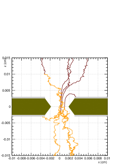
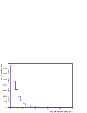
The detecting element of GEM detector is a 50 m polyimide foil sandwiched between 5 m layers of copper on both sides. For foils produced with double mask technology, the holes have an hour-glass like shape where the diameter of the outer openings have typical values of 70 m and the diameter of the constricted part is 50 m. Single mask technology produces holes with conical shape with typical hole diameters of 70 m and 60 m on either sides of the cone. A high electric field inside the hole is created and controlled by applying voltages on the metal layers. Electron multiplication happens when the electric field in the hole reaches a typical value of 10 kV/cm which is the limit of avalanche formation for the gas. The geometry of the hole, material properties of the GEM, the voltage applied to the metal layers and the boundary conditions are defined in ANSYS, which calculates the electric field mesh using finite element technique. The overall formation of the electron avalanche (Fig. 1) is simulated using Garfield++. This program has interfaces with HEED [8], which calculates the energy loss and ionisation of the gas molecules by moving charged particles and MAGBOLTZ[9], which computes the transport properties of the electrons subjected to the electric field. Finally for every single primary electron, the number of secondaries that cross the hole and reach certain distance below the bottom of the foil is counted. A distribution of this number for many thousands of avalanches is shown in Fig. 2. The mean of this distribution gives the gain.
3 Results
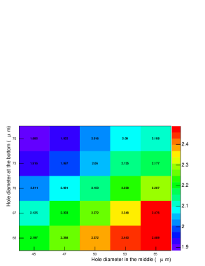
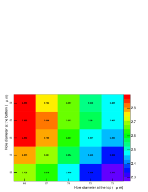
It is important to mention here that the charging up effect of the GEM foils has not been considered in this study. We have taken five values of each of the three hole diameters to calculate the gain for bi-conical holes, on the other hand five values of each of the two hole diameters have been taken for conical holes. 100 k avalanches have been simulated for each setting. (70:30) gas mixture has been used for all the calculations. The values of the drift field () and those of the induction field () have been taken as 400 V/cm and 1 kV/cm respectively. A potential difference () of 267 V has been applied across the foil. The variation of the gain as a function of different hole diameters for the double and the single mask GEM foils are shown in Fig. 3 and Fig. 4 respectively.
4 Summary and outlook
We have studied the variation of the gain of single GEM detector as a function of the shape of the holes using Garfield++ simulation package. The results reveal that this variation may reach up to 17-18% for a variation of 5 m in the hole diameter. It is understood that the charging up of the GEM foils in course of time might have effect on the results. However these findings are needed to be compared with the measured data for similar variation. The gain variation will be studied by changing other parameters such as gas mixture and as a continuation of this work. The results of this study will help in QA of the GEM foils where a large number of them is required such as in ALICE TPC.
Acknowledgements
This work was partially supported by the research grant SR/MF/PS-01/2014-BI from Department of Science and Technology, Govt. of India.
References
- [1]
- [2] C. Garabatos, Nucl. Instr. and Meth. A535 (2004) 197.
- [3] T. Gunji, Nucl. Instr. and Meth. A931 (2014) 1152.
- [4] F. Sauli, Nucl. Instr. and Meth. A386 (1997) 531.
- [5] T. Hildén et al., Nucl. Instr. and Meth. A770 (2015) 113.
- [6] http://www.ansys.com/
- [7] H. Schindler and R. Veenhof, http://garfieldpp.web.cern.ch/garfieldpp/
- [8] I. Smirnov, http://consult.cern.ch/writeup/heed/
- [9] S. Biagi, http://consult.cern.ch/writeup/magboltz/