Network MIMO with Partial Cooperation between Radar and Cellular Systems
Abstract
To meet the growing spectrum demands, future cellular systems are expected to share the spectrum of other services such as radar. In this paper, we consider a network multiple-input multiple-output (MIMO) with partial cooperation model where radar stations cooperate with cellular base stations (BS)s to deliver messages to intended mobile users. So the radar stations act as BSs in the cellular system. However, due to the high power transmitted by radar stations for detection of far targets, the cellular receivers could burnout when receiving these high radar powers. Therefore, we propose a new projection method called small singular values space projection (SSVSP) to mitigate these harmful high power and enable radar stations to collaborate with cellular base stations. In addition, we formulate the problem into a MIMO interference channel with general constraints (MIMO-IFC-GC). Finally, we provide a solution to minimize the weighted sum mean square error minimization problem (WSMMSE) with enforcing power constraints on both radar and cellular stations.
Index Terms:
MIMO Radar, Small Singular Values Space Projection, Radar Cellular Coexistence, Network MIMOI Introduction
Federal Communications Commission (FCC) and the National Telecommunications and Information Administration (NTIA) studies show very low utilization of huge chunks of spectrum held by the federal agencies, especially in urban areas. Meanwhile, there is a very heavy utilization of spectrum held by commercial operators, e.g. cellular operators, in these urban areas. President’s Council of Advisors on Science and Technology (PCAST) recommendations in order to efficiently utilize federal spectrum are to share federal spectrum with commercial operators [1]. The sharing will result in enormous economic and social advances for the nation. Meanwhile, this sharing should not endanger the main mission of federal incumbents, e.g. sharing radar spectrum should not affect its target tracking capabilities. Therefore, new approaches should be developed with these considerations in mind.
A recent report by NTIA [2] concluded that sharing radar spectrum with WiMAX requires huge exclusion zones up to tens of kilometers to protect the WiMAX receivers from harmful interference signal transmitted by radar. This is due to WiMAX receivers are designed to handle low power levels in the range of Watts while the power transmitted by radar is in the range of Kilo and Mega Watts. This includes shipborne radars that are deployed on military ships on the east and west coasts of the United States. Which in turn results in depriving these areas, i.e. where the majority of the US population live, from the benefits of sharing radar spectrum.
On the other hand, within the cellular system, interference is a major obstacle against achieving the spectral efficiency expected from developed multiple-antenna techniques [3]. It is shown in [4, 5] that multiple-input multiple-output (MIMO) capacity gains are deteriorated due to inter-cellular interference. In a radar/cellular coexistence scenario, radar receivers have highly sensitive receivers for detecting reflected signals from far targets. Therefore, it is highly susceptible to interference from commercial wireless system operating on radar bands. In the past, radar has been guaranteed exclusive rights to radio spectrum allocation to avoid its operation from being affected by commercial wireless systems interference [2, 6]. Therefore, a radar/cellular network-level interference management is of fundamental importance to sustain the radar/cellular coexistence along with limiting inter-cellular interference and harnessing the advantages of cellular MIMO technology.
To address the aforementioned challenges, we propose a novel coexistence scenario and model between radar and cellular system. In this model, the radar signal is steered to null-space plus small singular values space of the interference channel between the radar and cellular system. The approach benefits both radar and cellular systems. On the radar side, it will increase the projection space dimensions and therefore radar performance metrics are improved compared to projection with smaller dimensions, e.g. null space projection [7], see [8] for more details. On the cellular side, this approach suppresses the high power of radar in the direction of cellular network so it does not burn out the cellular receivers. In addition, the transmitted radar signal could be used to transmit communication messages to enhance the overall system performance and quality of service (QoS) of cellular system. In our model, we propose network MIMO with partial cooperation for merging radar stations in the cellular network.
I-A Related Work
To benefit from radar spectrum, researchers have proposed the use of spatial domain to mitigate MIMO radar interference to communication system [7]. One of the studies proposed projection of radar signal into the null space of the interference channel between radar and communication systems [9]. In another study, researchers designed radar waveform that doesn’t cause harmful interference with communication system and successfully achieves the radar mission objectives [10]. In the past, sharing of government bands has been allowed for commercial wireless systems under the condition of low power transmission in order to protect incumbent from harmful interference [11]. Famous examples are WiFi and Bluetooth at 2450-2490 MHz band, wireless local area network (WLAN) at the 5.25-5.35 and 5.47-5.725 GHz [12], and the recently proposed 3550-3650 MHz radar band for small cells usage, i.e. wireless BSs operating on low power [13].
In [14], network MIMO, also known as multi-cell cooperation, has shown network-level interference management that significantly improve cellular systems performance. In network MIMO, multiple BSs cooperate their transmission to each user. Network MIMO can be reduced to MIMO broadcast channel (BC) in case of full cooperation between all BSs as shown in [15]. In another scenario, network MIMO can be reduced to a MIMO interference channel (MIMO-IFC) in case of absence of collaboration between BSs shown in [15, 16, 17]. The general case is forming clusters of BSs that collaborate to transmit to a certain user [17, 18, 19, 20, 21].
I-B Our Contributions
Our contributions in this paper are as follows:
-
•
We propose a small singular values space projection method that facilitate coexistence between radar and cellular systems.
-
•
We incorporate radar stations in the cellular system and show the equivalence of the new model to MIMO interference channel with general constraints (MIMO-IFC-GC) model for network MIMO with partial cooperation shown in [3].
-
•
We provide a suboptimal solution of the weighted sum-MSE minimization (WSMMSE) problem in Section V for our proposed model.
Notation: Matrices and vectors are denoted by bold upper and lower case letters, respectively. Transpose and Hermitian operators are denoted by , and , respectively.
The paper is organized as follows. Section II discusses system model for MIMO downlink system with radar and cellular coexistence. Moreover, it discussed the user message precoding at radar and cellular stations. Section III describes how to construct small singular values space projection matrix. We show the equivalence of our proposed model with MIMO-IFC-GC in Section IV. Section V contains the WSMMSE minimization problem under investigation and Section VI presents its solution. Section VII concludes the paper.
II System Model
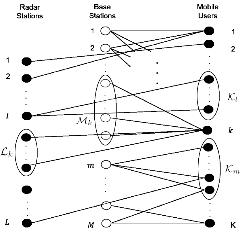
We consider a MIMO downlink system with radar stations, including shipborne radars, forming a set , cellular base stations (BSs) forming a set , and mobile users forming a set , see Figure 1. Each BS has antennas for transmission, each radar station has antennas for transmission, and each mobile user has antennas. The th BS has the messages for users set where . Similarly, the th radar has the messages for users set where . Therefore, the th user receives its intended message from a subset of BSs and a subset of radar stations radars . In total, th user receives its message from stations . This channel is generally referred to as MIMO interference channel with partial message sharing, see [3]. If , or , contains one user for each transmitter , or , then the model reduces to a standard MIMO interference channel (MIMO-IFC). When all transmitters cooperate in transmitting to all the users, i.e. and , then we have MIMO broadcast channel (MIMO-BC), when number of some transmitters cooperate, i.e. or , then we have multicast interference channel [20]. In this paper, we consider MIMO interference channel with partial message sharing (MIMO-IFC-PMS).
II-A Precoding
We define to represent the independent streams sent to user . It is assumed that . The data streams are known to all the cellular base stations in the set and all the radar stations in the set . Assuming , the th radar station precodes vector via a matrix , then projects it using projection matrix , which is described in Section III. The signal sent by radar station and received by the user can be given as,
Assuming is the allowed radar power level to the communication system, then power constraint is given by
Similarly, assuming , for the th base station, we have
| (1) |
and,
The th user receives the following signal:
where and are the channel matrices between the th radar station and th user and the th BS and th user, respectively, and is noise where .
III Small Singular Values Space Projection
In this section, we design our projection matrix such that steering the radar power in the direction of small singular values results in radar power that is in the order of communication transmit power, i.e. where is the radar transmit power and is a singular value threshold. As a result, the diminished radar power received at the communication system will not burnout or saturate the communication receivers. Given that the th MIMO radar has channel state information of and the th user. Let be the th user in the set . Therefore the augmented channel matrix between the th radar and the set of users is given by
| (4) |
We proceed by first finding SVD of , i.e.,
| (5) |
Now, let us define
| (6) |
where and are the singular values of . Next, we define
| (7) |
where
| (8) |
Using above definitions, we can now define our small singular values space projection matrix . Note that is a projection matrix as it satisfies and .
IV Equivalence with MIMO-IFC-GC
The MIMO-IFC-GC consists of transmitters with antennas at the the th transmitter and receivers with antennas at the th receiver. The th receiver received signal is given by:
| (9) |
where is additive complex Gaussian noise , are the inputs to receiver and is the channel matrix between the th transmitter and the th receiver. The th user intended information stream vector is where and . In this model, the th user precoding matrix is given by therefore . The input vectors have to satisfy both the generalized linear constraints given by
and generalized linear constraints given by
| (10) |
for and and and are weight matrices where are positive definite for all .
Lemma IV.1.
Assume that the base station or radar station in subset is given by the index is informed about user ’s message. The MIMO-IFC-PMS is a special case of a MIMO-IFC-GC with , , channel matrices
augmented precoding (beamforming) matrices,
and weight matrices with the submatrix on the main diagonal is , if and the rest of the matrix elements are zeros and with the submatrix on the main diagonal is , if and the rest of the matrix elements are zeros. If then and if then .
Proof.
It is easy to show by inspection. ∎
Remark IV.2.
The effect of small singular values space projection on the MIMO-IFC-GC equivalent model is only in the augmented channel matrix or the weight matrices which are inputs to the optimization problem as shown in section V.
V Optimization Problem
Given the equivalence between MIMO-IFC-GC and the proposed Network MIMO with partial cooperation for radar and cellular systems model. The rest of the paper shows how to use a modified version of the receiver in [3] for our new proposed system model. The th user uses the equalization matrix to estimate its message as
| (11) |
Therefore, the Mean Square Error (MSE)-matrix for user is given by
| (12) |
Using the equivalent MIMO-IFC-GC model, the MSE-matrix can be written as
| (13) |
where
| (14) |
For each user , the equalization matrices can be evaluated using the MMSE solution as
| (15) |
In this paper, we focus on the weighted sum-MSE minimization (WSMMSE) problem given by the following:
| (16) | ||||||
| subject to | ||||||
where are the diagonal weight matrices with non-negative weights.
VI MMSE Minimization
The extended MMSE interference alignment (eMMSE-IA) technique applied to an interference channel with per-transmitter power constraints and where each receiver is endowed with multiple antenna [3], is extended here to include radar system coexisting with communication system. The technique starts by an arbitrarily . Then, at each iteration the equalization matrix is evaluated using (15) resulting in
| (17) |
where,
| (18) |
Given the matrices , the optimization problem (16) becomes
| (19) | ||||||
| subject to | ||||||
where as in (V) with instead of . For a fixed , the optimization problem in (19) is convex and therefore there exists a unique global optimal solution for . Using KKT conditions, we have
where are Lagrangian multipliers satisfying
| (20) |
and are Lagrangian multipliers satisfying
| (21) |
Using , the iterative algorithm continues with the th iteration.
VII Conclusion
In this paper, we considered a network MIMO with partial cooperation model where radar stations cooperate with cellular base stations (BS)s to deliver messages to intended mobile users. We designed a new projection matrix to mitigate radar stations interference to cellular system. In addition, this projection provides useful enhancement to the cellular system performance and QoS when radar stations cooperate in communication messages delivery. We showed that our constructed model, i.e. the radar stations act as BSs in the cellular system, is equivalent to a MIMO interference channel under generalized linear constraints (MIMO-IFC-GC). Finally, we provided a solution to minimize the weighted sum mean square error minimization problem (WSMMSE) with enforcing power constraints on both radar and cellular stations.
VIII Future Work
Comparison with other MSE minimization schemes will be considered in our future work. In addition, we plan to conduct a study on the sum rate maximization improvement for the new proposed model.
References
- [1] The President s Council of Advisors on Science and Technology (PCAST), “Realizing the full potential of government-held spectrum to spur economic growth,” July 2012.
- [2] National Telecommunications and Information Administration (NTIA), “Analysis and resolution of RF interference to radars operating in the band 2700-2900 MHz from broadband communication transmitters.” Online, October 2012.
- [3] S. Kaviani, O. Simeone, W. Krzymien, and S. Shamai, “Linear precoding and equalization for network mimo with partial cooperation,” Vehicular Technology, IEEE Transactions on, vol. 61, pp. 2083–2096, Jun 2012.
- [4] H. Dai, A. Molisch, and H. Poor, “Downlink capacity of interference-limited mimo systems with joint detection,” Wireless Communications, IEEE Transactions on, vol. 3, pp. 442–453, March 2004.
- [5] R. Blum, “MIMO capacity with interference,” Selected Areas in Communications, IEEE Journal on, vol. 21, pp. 793–801, June 2003.
- [6] A. Khawar, A. Abdel-Hadi, and T. Clancy, “A mathematical analysis of lte interference on the performance of s-band military radar systems,” in 13th Annual Wireless Telecommunications Symposium (WTS).
- [7] A. Khawar, A. Abdel-Hadi, T. C. Clancy, and R. McGwier, “Beampattern analysis for MIMO radar and telecommunication system coexistence,” in IEEE International Conference on Computing, Networking and Communications, Signal Processing for Communications Symposium (ICNC’14 - SPC), 2014.
- [8] A. Khawar, A. Abdelhadi, and T. C. Clancy, “QPSK waveform for MIMO radar with spectrum sharing constraints,” CoRR, vol. abs/1407.8510, 2014.
- [9] A. Khawar, A. Abdelhadi, and T. Clancy, “On the impact of time-varying interference-channel on the spatial approach of spectrum sharing between s-band radar and communication system,” in Military Communications Conference (MILCOM), 2014 IEEE, pp. 807–812, Oct 2014.
- [10] A. Khawar, A. Abdel-Hadi, and T. C. Clancy, “MIMO radar waveform design for coexistence with cellular systems,” in 2014 IEEE International Symposium on Dynamic Spectrum Access Networks: SSPARC Workshop (IEEE DySPAN 2014 - SSPARC Workshop), (McLean, USA), Apr. 2014.
- [11] A. Khawar, A. Abdelhadi, and C. Clancy, “Target detection performance of spectrum sharing mimo radars,” Sensors Journal, IEEE, vol. 15, pp. 4928–4940, Sept 2015.
- [12] Federal Communications Commission (FCC), “In the matter of revision of parts 2 and 15 of the commission s rules to permit unlicensed national information infrastructure (U-NII) devices in the 5 GHz band.” MO&O, ET Docket No. 03-122, June 2006.
- [13] Federal Communications Commission (FCC), “FCC proposes innovative small cell use in 3.5 GHz band.” Online: http://www.fcc.gov/document/fcc-proposes-innovative-small-cell-use-35-ghz-band, December 12, 2012.
- [14] D. Gesbert, S. Hanly, H. Huang, S. Shamai Shitz, O. Simeone, and W. Yu, “Multi-Cell MIMO Cooperative Networks: A New Look at Interference,” Selected Areas in Communications, IEEE Journal on, vol. 28, pp. 1380–1408, December 2010.
- [15] H. Weingarten, Y. Steinberg, and S. Shamai, “The Capacity Region of the Gaussian Multiple-Input Multiple-Output Broadcast Channel,” Information Theory, IEEE Transactions on, vol. 52, pp. 3936–3964, Sept 2006.
- [16] V. Cadambe and S. Jafar, “Interference Alignment and Degrees of Freedom of the K -User Interference Channel,” Information Theory, IEEE Transactions on, vol. 54, pp. 3425–3441, Aug 2008.
- [17] M. Maddah-Ali, A. Motahari, and A. Khandani, “Communication over MIMO X channels: Interference alignment, decomposition, and performance analysis,” Information Theory, IEEE Transactions on, vol. 54, pp. 3457–3470, Aug 2008.
- [18] H. Huang, M. Trivellato, A. Hottinen, M. Shafi, P. Smith, and R. Valenzuela, “Increasing downlink cellular throughput with limited network MIMO coordination,” Wireless Communications, IEEE Transactions on, vol. 8, pp. 2983–2989, June 2009.
- [19] J. Zhang, R. Chen, J. Andrews, A. Ghosh, and R. Heath, “Networked MIMO with clustered linear precoding,” Wireless Communications, IEEE Transactions on, vol. 8, pp. 1910–1921, April 2009.
- [20] A. Abdel-Hadi and S. Vishwanath, “On multicast interference alignment in multihop networks,” IEEE Information Theory Workshop, Cairo, EGYPT, 2010.
- [21] J. Jose, A. Abdel-Hadi, P. Gupta, and S. Vishwanath, “Impact of mobility on multicast capacity of wireless networks,” IEEE InfoCom, San Diego, CA, USA, 2010.