Large cooperativity and microkelvin cooling with a three-dimensional optomechanical cavity
In cavity optomechanics, light is used to control mechanical motion. A central goal of the field is achieving single-photon strong coupling, which would enable the creation of quantum superposition states of motion. Reaching this limit requires significant improvements in optomechanical coupling and cavity coherence. Here, we introduce a new optomechanical architecture consisting of a silicon-nitride membrane coupled to a three-dimensional superconducting microwave cavity. Exploiting their large quality-factors, we achieve an optomechanical cooperativity of 146,000 and perform sideband cooling of the kilohertz-frequency membrane motion to microkelvin, the lowest mechanical mode temperature reported to date. The achieved cooling is limited only by classical noise of the signal generator, and should extend deep into the ground state with superconducting filters. Our results suggest that this new realisation of optomechanics has the potential to reach the regimes of ultra-large cooperativity and single-photon strong coupling, opening up a new generation of experiments.
In recent years, cavity optomechanics has been used to realise a wide range of exciting experiments with mechanical resonators, including achieving exquisite measurement precision teufel_nanomechanical_2009 ; anetsberger_measuring_2010 ; wilson_measurement_2014 , strong-coupling between the mechanical and cavity modes Groblacher2009 ; Teufel2011a ; Verhagen2012 , cooling to the quantum ground state Teufel2011 ; Chan2011 , for microwave amplification massel_microwave_2011 ; Singh2014 , to entangle propagating microwave photons with mechanical motion Palomaki08112013 , for microwave photon storage palomaki_coherent_2013 ; zhou_slowing_2013 , to observe quantum backaction noise Purdy2013a , to generate squeezed light squeezing2013 ; Purdy2013 , and to transduce photons between the optical and microwave domains bochmann_nanomechanical_2013 ; Andrews2014 ; Bagci2014 . These successful experiments, performed in the regime of linear optomechanics, were enabled by improvements of the coherence of the optomechanical coupling between light and motion.
In linear optomechanics, the relevant figure of merit for the optomechanical coupling is a parameter called cooperativity. Cooperativity combines the optomechanical coupling rate , the cavity decay rate , and the mechanical decay rate , into a dimensionless constant that quantifies the optomechanical system’s efficiency in exchanging photons and phonons RevModPhys.86.1391 . It is similar to the Purcell factor in atomic physics (also often referred to as cooperativity) describing the coupling between cavity fields and atoms. An advantage of linear optomechanics is that compared to the single-photon coupling rate , the multiphoton coupling rate is significantly enhanced, given by where is the number of photons used to drive the cavity. The relevant limit for cooperativity in quantum experiments is the so-called quantum coherent limit, in which the cooperativity is larger than the number of equilibrium thermal quanta in the mechanical resonator. In the quantum coherent limit, an exchange of a photon and phonon occurs faster than the time it takes for a phonon to leak into the mechanical resonator ground state from the thermal bath. Achieving higher cooperativity that is deeper in the quantum coherent limit in linear optomechanics would imply the ability to cool closer to the quantum ground state and the preparation of mechanical quantum states with high fidelity.
Beyond linear optomechanics, the field is striving to reach the limit of single-photon strong coupling, in which interaction of light and mechanical motion is coherent at the level of a single photon. In this limit, the single-photon coupling rate exceeds both the cavity decay rate and the mechanical decay rate (). If one could reach this limit, one could take advantage of the intrinsic non-linearity of the optomechanical coupling at the single-photon level to construct quantum superpositions of mechanical motion using optomechanics with classical light. In current experiments, , and existing optomechanical implementations would require significant improvements in and/or to approach single-photon strong coupling.
Here, we present a new optomechanical architecture with large optomechanical coupling that can potentially reach the single-photon strong coupling limit. The design combines two highly coherent elements that are applied for the first time in the microwave optomechanics domain. The first element is a millimetre-sized, nanometre-thick high-stress silicon nitride (SiNx) membrane, a technology that has demonstrated quality factors up to at cryogenic temperatures Zwickl2008 . Such membranes have been used extensively in the optical domain Thompson2008 ; Purdy2013 ; Purdy2013a ; Regal2014 ; Harris2014 and in transducer applications Andrews2014 ; Bagci2014 , but have not yet been explored as an element in a pure microwave optomechanical system. The second optomechanical element is a three-dimensional (3D) microwave cavity, recently popular in the superconducting qubit community for their exceptional coherence times Paik2011 ; kirchmair2013observation ; Reagor2013 . By combining these two highly coherent elements, we create a new optomechanical platform with large cooperativity, demonstrate cooling to the lowest mechanical mode temperature reported to date, and show that this new system has the potential to scale to couplings significantly beyond the state-of-the-art.
Results
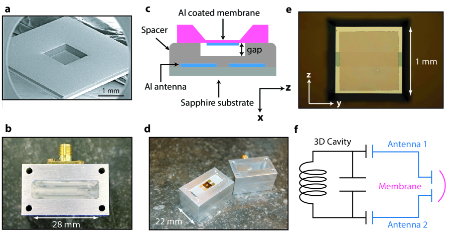
Description and characterisation of the device. Fig. 1 illustrates the principle of this new 3D optomechanical platform. The mechanical resonator is made from high-stress SiNx membrane (Fig. 1a) that is metallised with an Al electrode. The cavity itself is an aluminium box, Fig. 1b, in which electromagnetic fields are confined by superconducting walls in all three dimensions. Coupling to the motion of the membrane is achieved by using a flip-chip technique to place the membrane on top of antenna electrodes on a separate substrate, Fig. 1c-e. Fig. 1f shows an effective lumped-element circuit model of the assembled cavity and membrane. Optomechanical coupling results from the modulation of the effective shunt capacitance when the membrane displaces, changing the cavity frequency. From finite-element simulations, we estimate a single photon coupling rate of Hz, where is the cavity mode frequency, is the mechanical displacement of the membrane and is the amplitude of its zero-point fluctuation. The simplicity of the assembly of this 3D cavity architecture also makes it attractive for implementing devices such as microwave-to-optical transducers bochmann_nanomechanical_2013 ; Andrews2014 ; Bagci2014 by potentially incorporating an optical fiber into the superconducting box.
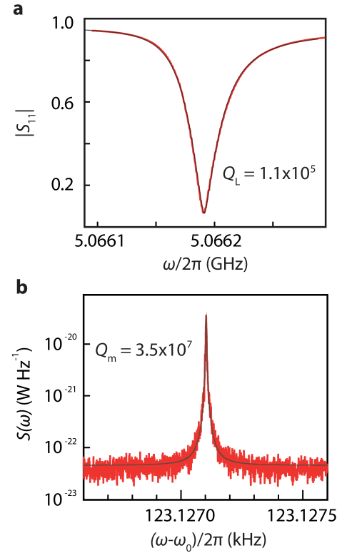
Measurements are performed in a dilution refrigerator with a base temperature of mK (see Supplementary Figure 1 and Supplementary Note 1). Fig. 2a shows a measurement of the reflection coefficient of the cavity. From a fit to the data, we find a total linewidth of kHz, corresponding to a loaded quality factor of . From power dependence, we find a maximum intracavity photon occupation before the onset of a nonlinear response. The ratio of the external decay rate and indicates that the cavity is slightly undercoupled (see Supplementary Figure 2 and Supplementary Note 2).
In Fig. 2b, we characterise the mechanical response of the membrane with the cavity using a resonant microwave tone injected at . The thermomechanical motion of the membrane generates a peak in the sideband power spectral density (PSD) of the microwave field leaving the cavity at a frequency offset from the carrier signal, shown in Fig. 2b. We find a mechanical resonance frequency of kHz, consistent with expected fundamental mode frequency of the membrane. A Lorentzian fit yields a linewidth of mHz, corresponding to an ultra-high mechanical quality factor of , significantly higher than the typical of membranes used in optomechanical and transducer experiments.
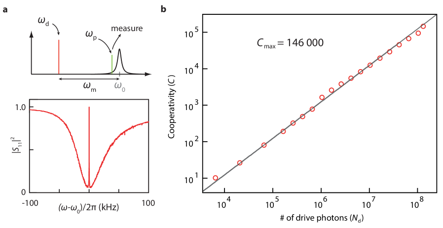
Large cooperativity. To quantify the strength of the optomechanical coupling, in Fig. 3 we measure the cooperativity between the mechanical resonator and the cavity. Together with initial phonon occupancy of the mechanical resonator , several criteria can be conveniently expressed with , such that for reaching the quantum ground state of motion, , or for reaching the radiation pressure shot noise limit, . To measure , we use optomechanically-induced transparency (OMIT) Weis10122010 ; PhysRevA.81.041803 ; Singh2014 , which allows one to directly determine the cooperativity with no free fit parameters. In OMIT, illustrated in Fig. 3a, the cavity is driven by a strong drive tone () while a second weak probe () is used to measure the cavity response. When driven on the red sideband (), a transparency window appears within the broad resonance dip of the cavity reflection coefficient Singh2014 . In the limit , the linewidth of the transparency window in is given by and the peak value by . Fig. 3b shows an example of an OMIT measurement with drive-photon number : from the broadened linewidth of the feature together with its near unity transmission, we extract . Fig. 3c shows the extracted for different drive powers: at the maximum power sustained by the cavity, we achieve .
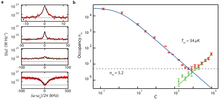
Microkelvin cooling of the membrane resonator. The large cooperativity of our optomechanical setup is, in principle, capable of cooling deep into the quantum ground state of motion if the mode is thermalised to the temperature of the fridge (). In order to demonstrate the cooling of the resonator, in Fig. 4 we use the spectral density of the thermomechanical sideband to directly observe the phonon occupation of the membrane. While driving the cavity on the red sideband, the output microwave PSD at the cavity resonance frequency is given by:
| (1) |
where is the measured microwave PSD on the spectrum analyser, is the net gain of the signal path from the output of the cavity to the input of the spectrum analyser, and is the added photon noise quanta from the amplification chain referenced to the output of the cavity. By varying the bath temperature and measuring , we obtain an absolute calibration of , , and (details provided in Supplementary Figure 3 and Supplementary Note 3, 4). At the base temperature of the refrigerator, we find that the membrane is thermalised to mK, corresponding to . From the thermal calibration, we also extract Hz, in good agreement with simulations (Supplementary Figure 4 and Supplementary Note 5).
Fig. 4a shows for different cooperativities of the cooling tone. As increases, from the thermomechanical noise peak decreases, indicating that the mode temperature of the mechanical resonator is reduced. At larger cooling powers, however, although continues to drop, the noise floor of outside the mechanical bandwidth begins to increase, and the peak in the PSD becomes a dip (bottom two panels of Fig. 4a). The increase in the noise floor is an indication of noise fluctuations of the cavity field Teufel2011 . Due to correlations between the fluctuations of the cavity and of the mechanical resonator, the spectrum shows a suppression of the total PSD at the cavity frequency PhysRevLett.99.017201 .
In order to extract the mechanical occupation factor in the presence of cavity noise, it is no longer sufficient to look only at . In particular, with sufficiently large (and in the absence of other sources of heating that would increase such as losses in the superconducting film or in the dielectric membrane or substrate), drops to the amplifier noise floor independent of the amount of cavity noise (Eq. 1). This does not, however, imply that the mechanical mode is at zero temperature: due to the hybridisation of the mechanical and optical fields, the final mechanical mode occupation in the presence of cavity noise is given by (Supplementary Note 6):
| (2) |
where is the cavity noise power measured in energy quanta. In order to find the final occupation , one must also determine . In the limit , cavity noise appears as an increase in the noise floor outside of the mechanical sideband (green dashed line in Fig. 4a) with a spectral density (see Supplementary Note 6 for the more general equation of ):
| (3) |
where . From this expression, one can extract the cavity occupation and consequently for all powers, shown in Fig. 4b. As is increased, we find that drops initially to a value of , corresponding to a mode temperature of K, beyond which the mechanical occupation begins to increase sharply due to heating from cavity noise. The temperature reported here is roughly a factor of two lower than recent experiments in the optical domain with silicon nitride membranes Regal2014 ; Harris2014 due to the very low frequency of our membrane.
Although the large cooperativity in our experiment should allow us to cool the membrane to given the initial thermal occupation, in practice we are limited to by cavity noise. In order to cool to lower occupation in future experiments, it is important to identify the source of this cavity noise. The green line in Fig. 4b shows the expected due to the carrier sideband noise of our microwave signal generator (Supplementary Note 7). The good agreement with the observed cavity noise data suggests that our final occupation is limited by the spectral purity of the microwave tone used for the sideband cooling.
Discussion
Having demonstrated the lowest temperature K reported to date for a mechanical resonator, we analyse the potential of this new implementation to reach the deep quantum coherent coupling limit. In the current experiment, the cooling is limited by the classical sideband noise of the signal generator. Removing this noise with a tunable superconducting cavity with a linewidth of 10 kHz would already provide sufficient suppression to cool to a final occupation of 0.2. A second approach would be to increase by shrinking the capacitor gap: reducing the membrane-antenna gap from 3 m to 100 nm would increase by a factor of and by . A third approach is to improve the cavity linewidth Reagor2013 , also yielding higher cooperativity at lower photon numbers. Finally, combining a smaller gap ( Hz) with a better cavity ( Hz) could yield ultra-high cooperativities . Such a fully optimised design would also achieve single-photon strong coupling () rabl2011photon ; PhysRevLett.107.063602 , enabling preparation and detection of non-classical states of motion such as Fock states or Schrödinger cat states with optomechanics.
In conclusion, we have developed a novel optomechanical system coupling the motion of a millimetre-sized membrane to a 3D microwave cavity. Exploiting the high coherence of the membrane and of the cavity, we achieve a cooperativity of and perform sideband cooling of the millimetre-size membrane to 34 K, corresponding to a thermal occupation . The scaling of this 3D optomechanical system offers the possibility to reach optomechanical couplings far beyond the state-of-the-art, potentially entering the single-photon strong coupling regime in which a new generation of quantum experiments with mechanical objects would become possible.
Acknowledgments We would like to thank S. J. Bosman, S. Yanai, S. Gröblacher, L. DiCarlo, D. Ristè and R. Hoogerheide for discussions and support. Fabrication is carried out in Kavli Nanolab and this project is supported by the Stichting voor Fundamenteel Onderzoek der Materie (FOM).
Author Contribution G. A. S. conceived the device and supervised the project. M. Y. prepared the devices. M. Y. and V. S. set up the experiment and performed the measurements. M. Y., V. S. and G. A. S. analysed the data. M. Y. and Y. M. B. performed the theoretical calculation. All authors contributed to writing of the manuscript.
Methods
Device preparation. We use commercial SiNx membranes manufactured by Norcada. The membranes have the dimensions of , and are supplied with a 5 mm 5 mm Si frame. We deposit a 20 nm thick film of Al on top of the membrane without covering the clamping edges by using a physical mask. On a separate sapphire substrate, we pattern two Al antenna pads with 80 nm of Al followed by the deposition of SiNx spacer layer. To ensure the membrane does not come into contact with the substrate, a recess of 100 nm is etched. The metallised SiNx membrane is then placed on top of the antenna pads to form a capacitor using a vacuum pick-and-place technique. A single drop of 0.1 l of 2-part epoxy is applied on the substrate to attach one corner of the membrane’s Si frame to the substrate. Using the depth of focus to locate the vertical position of the membrane and of the bottom antenna pads while looking through the membrane with an optical microscope, we estimate the gap to be approximately m. The gap is much larger than that designed in the spacer, most likely due to contamination from dust in the large contact area between the Si frame of the membrane and the substrate. The 3D microwave cavity is formed by closing two halves of a machined block made out of 6061-aluminium. The inner surface of the cavity is polished using a polishing paste, but is not chemically etched. The cavity is assembled by screwing the two halves of the cavity together with no sealing mechanism. The dimension of the whole cavity is 28 mm(x)28 mm(y)8 mm(z), with rounded corners of radius 1 mm in the y-z plane.
Measurement. The bare frequency of the cavity without the antenna substrate and membrane is 7.4 GHz. The membrane attached to the antenna is placed at the centre of the cavity, coupling to the TE110 mode. We estimate the total mass of the membrane including the Al layer to be ng, corresponding to an estimated quantum zero-point fluctuation of fm. Measurements are performed in a cryogen free dilution refrigerator. To minimise cavity instability during the measurements, the sample is mounted on a mass-spring vibration isolation stage on the mixing chamber with resonance frequency of Hz. During the cooling measurements, the pulse tube is temporarily turned off to minimise vibrations of the sample and the cables. Measurements are started 1.5 minutes after the switch-off and performed in a minute window before the temperature of the mixing chamber begins to increase.
References
- (1) Teufel, J. D., Donner, T., Castellanos-Beltran, M. A., Harlow, J. W. & Lehnert, K. W. Nanomechanical motion measured with an imprecision below that at the standard quantum limit. Nature Nanotechnology 4, 820–823 (2009).
- (2) Anetsberger, G. et al. Measuring nanomechanical motion with an imprecision below the standard quantum limit. Physical Review A 82, 061804 (2010).
- (3) Wilson, D. J. et al. Measurement and control of a mechanical oscillator at its thermal decoherence rate. Preprint at: http://arXiv.org/abs/1410.6191 (2014).
- (4) Gröblacher, S., Hammerer, K., Vanner, M. R. & Aspelmeyer, M. Observation of strong coupling between a micromechanical resonator and an optical cavity field. Nature 460, 724–727 (2009).
- (5) Teufel, J. D. et al. Circuit cavity electromechanics in the strong-coupling regime. Nature 471, 204–208 (2011).
- (6) Verhagen, E., Deléglise, S., Weis, S., Schliesser, a. & Kippenberg, T. J. Quantum-coherent coupling of a mechanical oscillator to an optical cavity mode. Nature 482, 63–67 (2012).
- (7) Teufel, J. D. et al. Sideband cooling of micromechanical motion to the quantum ground state. Nature 475, 359–363 (2011).
- (8) Chan, J. et al. Laser cooling of a nanomechanical oscillator into its quantum ground state. Nature 478, 89–92 (2011).
- (9) Massel, F. et al. Microwave amplification with nanomechanical resonators. Nature 480, 351–354 (2011).
- (10) Singh, V. et al. Optomechanical coupling between a multilayer graphene mechanical resonator and a superconducting microwave cavity. Nat. Nanotechnol. 9, 820–824 (2014).
- (11) Palomaki, T. A., Teufel, J. D., Simmonds, R. W. & Lehnert, K. W. Entangling mechanical motion with microwave fields. Science 342, 710–713 (2013).
- (12) Palomaki, T. A., Harlow, J. W., Teufel, J. D., Simmonds, R. W. & Lehnert, K. W. Coherent state transfer between itinerant microwave fields and a mechanical oscillator. Nature 495, 210–214 (2013).
- (13) Zhou, X. et al. Slowing, advancing and switching of microwave signals using circuit nanoelectromechanics. Nature Physics 9, 179–184 (2013).
- (14) Purdy, T. P., Peterson, R. W. & Regal, C. A. Observation of radiation pressure shot noise on a macroscopic object. Science 339, 801–804 (2013).
- (15) Safavi-Naeini, A. H. et al. Squeezed light from a silicon micromechanical resonator. Nature 500, 185 – 189 (2013).
- (16) Purdy, T. P., Yu, P.-L., Peterson, R. W., Kampel, N. S. & Regal, C. A. Strong optomechanical squeezing of light. Phys. Rev. X 3, 031012 (2013).
- (17) Bochmann, J., Vainsencher, A., Awschalom, D. D. & Cleland, A. N. Nanomechanical coupling between microwave and optical photons. Nature Physics 9, 712–716 (2013).
- (18) Andrews, R., Peterson, R. & Purdy, T. Bidirectional and efficient conversion between microwave and optical light. Nature Phys. 10, 321–326 (2014).
- (19) Bagci, T. et al. Optical detection of radio waves through a nanomechanical transducer. Nature 507, 81–85 (2014).
- (20) Aspelmeyer, M., Kippenberg, T. J. & Marquardt, F. Cavity optomechanics. Rev. Mod. Phys. 86, 1391–1452 (2014).
- (21) Zwickl, B. M. et al. High quality mechanical and optical properties of commercial silicon nitride membranes. Appl. Phys. Lett 92, 103125 (2008).
- (22) Thompson, J. D. et al. Strong dispersive coupling of a high-finesse cavity to a micromechanical membrane. Nature 452, 72–75 (2008).
- (23) Purdy, T. P. et al. Optomechanical raman-ratio thermometry. eprint Preprint at: http://arxiv.org/abs/1406.7247 (2014).
- (24) Lee, D. et al. Observation of quantum motion in a nanogram-scale object. eprint Preprint at: http://arxiv.org/abs/1406.7254 (2014).
- (25) Paik, H. et al. Observation of high coherence in Josephson junction qubits measured in a three-dimensional circuit QED architecture. Phys. Rev. Lett. 107, 240501 (2011).
- (26) Kirchmair, G. et al. Observation of quantum state collapse and revival due to the single-photon kerr effect. Nature 495, 205–209 (2013).
- (27) Reagor, M. et al. Reaching 10‚Äâms single photon lifetimes for superconducting aluminum cavities. Appl. Phys. Lett. 102, 192604 (2013).
- (28) Weis, S. et al. Optomechanically induced transparency. Science 330, 1520–1523 (2010).
- (29) Agarwal, G. S. & Huang, S. Electromagnetically induced transparency in mechanical effects of light. Phys. Rev. A 81, 041803 (2010).
- (30) Poggio, M., Degen, C. L., Mamin, H. J. & Rugar, D. Feedback cooling of a cantilever’s fundamental mode below 5 mk. Phys. Rev. Lett. 99, 017201 (2007).
- (31) Rabl, P. Photon blockade effect in optomechanical systems. Phys. Rev. Lett. 107, 063601 (2011).
- (32) Nunnenkamp, A., Børkje, K. & Girvin, S. M. Single-photon optomechanics. Phys. Rev. Lett. 107, 063602 (2011).