Design and experimental demonstration of optomechanical paddle nanocavities
Abstract
We present the design, fabrication and initial characterization of a paddle nanocavity consisting of a suspended sub-picogram nanomechanical resonator optomechanically coupled to a photonic crystal nanocavity. The optical and mechanical properties of the paddle nanocavity can be systematically designed and optimized, and key characteristics including mechanical frequency easily tailored. Measurements under ambient conditions of a silicon paddle nanocavity demonstrate an optical mode with quality factor 6000 near nm, and optomechanical coupling to several mechanical resonances with frequencies MHz, effective masses fg, and mechanical quality factors . Paddle nanocavities are promising for optomechanical sensing and nonlinear optomechanics experiments.
Ultrasensitive measurement and control of local dynamics on the nanoscale can be achieved with cavity optomechanical systems whose optical modes are coupled to mechanical resonances Aspelmeyer, Kippenberg, and Marquardt (2014); Favero and Marquardt (2014). The interaction between photons and phonons within these devices can be enhanced by optical nanocavities with wavelength–scale dimensions Eichenfield et al. (2009a, b), and many recent theoretical proposals and experiments have shown that it is possible to optically probe the quantum properties of mesoscopic mechanical systems. Applications of cavity optomechanics Metcalfe (2014) include ultrasensitive displacement and force detection Arcizet et al. (2006); Li, Pernice, and Tang (2009); Anetsberger et al. (2010); Krause et al. (2012); Liu et al. (2012); Wu et al. (2014), optical cooling of a mechanical mode to its quantum ground-state Chan et al. (2011), and optical squeezing Safavi-Naeini et al. (2013). Cavity optomechanical coupling can be both dispersive and dissipative Wu et al. (2014), and in some systems, including ‘membrane in the middle’ systems Sankey et al. (2010); Flowers-Jacobs et al. (2012); Karuza et al. (2013), whispering gallery mode devices Doolin et al. (2014); Brawley et al. (2014) and photonic crystal optomechanical cavities Paraïso et al. (2015) can have nonlinear contributions. Nonlinear optomechanical coupling is predicted to enable observation of quantum non-demolition (QND) measurements of phonon number Thompson et al. (2008); Gangat, Stace, and Milburn (2011), measurement of phonon shot noise Clerk, Marquardt, and Harris (2010), and mechanical cooling and squeezing Bhattacharya, Uys, and Meystre (2008); Nunnenkamp et al. (2010); Biancofiore et al. (2011). Optomechanical paddle nanocavities are predicted to have large nonlinear optomechanical coupling Kaviani et al. (2015); Paraïso et al. (2015) owing to their fg-scale effective masses , relatively low [MHz] mechanical frequencies , and correspondingly large zero point fluctuation amplitudes . Here we present a procedure for the optical and mechanical design of an optomechanical paddle nanocavity and experimentally demonstrate its optomechanical coupling.
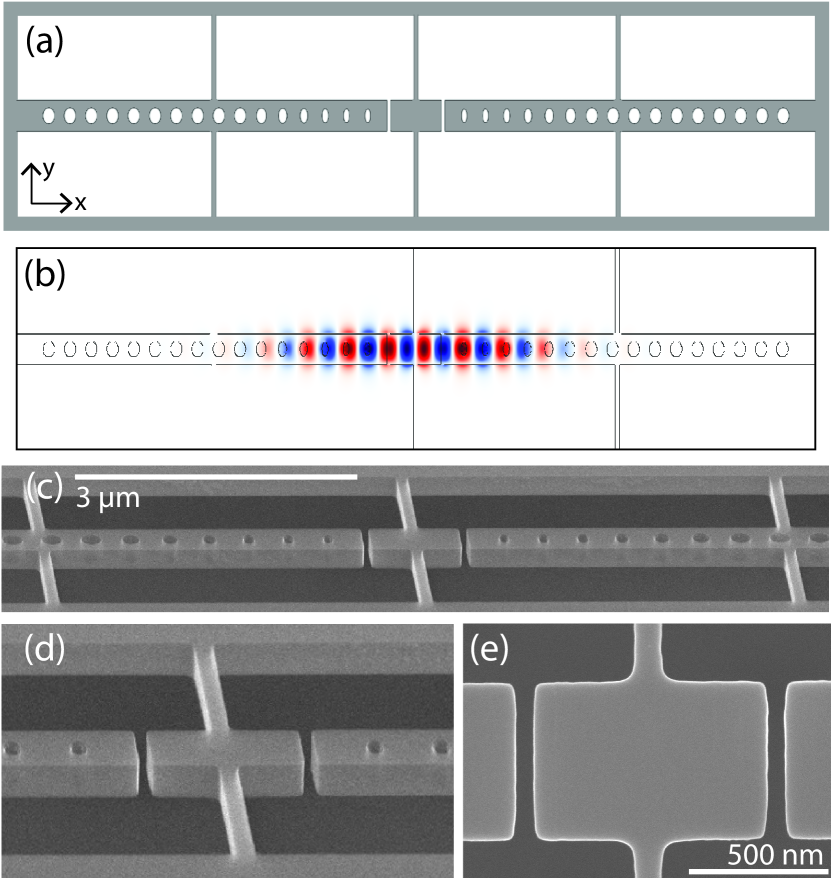
The paddle nanocavity device demonstrated in this letter, shown schematically and after fabrication in Figure 1, consists of photonic crystal Bragg mirrors patterned in opposing nanocantilevers, with a low-frequency and small effective-mass paddle mechanical oscillator suspended between them. When the nanobeam Bragg mirrors are patterned appropriately, the device forms a high quality factor () optical cavity whose optical modes overlap with the mechanical resonances of the paddle. Below we show how the device can be systematically designed and optimized to support high- modes despite the large perturbation to the photonic crystal lattice created by the paddle. We then experimentally demonstrate optomechanical coupling between a high- optical mode and both paddle and nanobeam mechanical resonances of a fabricated device.
The paddle nanocavities presented here use the split-beam photonic crystal nanocavity Hryciw and Barclay (2013); Wu et al. (2014), developed by Hryciw et al., as a basis. This geometry is shown schematically in Fig. 2(a), and will be described before analyzing the paddle nanocavity. Split-beam structures can be deterministically designedQuan, Deotare, and Loncar (2010); Quan and Loncar (2011) to support a high- even air-mode Hryciw and Barclay (2013) and the structure as discussed here is intended to be fabricated from silicon-on-insulator (SOI) chips, with nanobeam width = 600 nm and thickness = 220 nm, lattice constant = 400 nm, and hole semi-minor and semi-major axes that taper quadratically. The tapering smoothly increases (decreases) the air filling fraction away from the nanocavity centre for an air mode (dielectric mode) whose optical intensity overlaps with the low-index air (high-index dielectric) regions of the structure. Before introducing a gap in the nanocavity center, the design procedure determines central hole dimensions that match the unit-cell band-edge with the target nanocavity resonance frequency , and the outer ’mirror’ hole dimensions to maximize the mirror strength , where is the lower (upper) band edge frequency of the mirror region, and is the mid-gap frequency. Starting from an elliptical central hole with radii (, ) = (28.8, 275) nm, we quadratically taper these dimensions over cavity holes with for integer to external mirror hole dimensions (, ) = (100, 140) nm. Figure 2(b) shows the hole dimensions and the corresponding for each hole in this design. A gap is introduced with width , determined by comparing the band structure of the gap and central hole unit cells Hryciw and Barclay (2013). As previously found by HryciwHryciw and Barclay (2013), a smoothly varying optical potential is achieved by matching the gap unit cell air-mode band-edge with the ideal central hole dielectric mode band-edge. The resulting split-beam nanocavity is predicted by finite difference time domain (FDTD) simulationsHryciw and Barclay (2013); Oskooi et al. (2010) to support an optical mode with = 3.3 at a wavelength = 1583 nm ( THz). This high- is in part due to the highly elliptical shape of the cavity holes which resemble the gap.
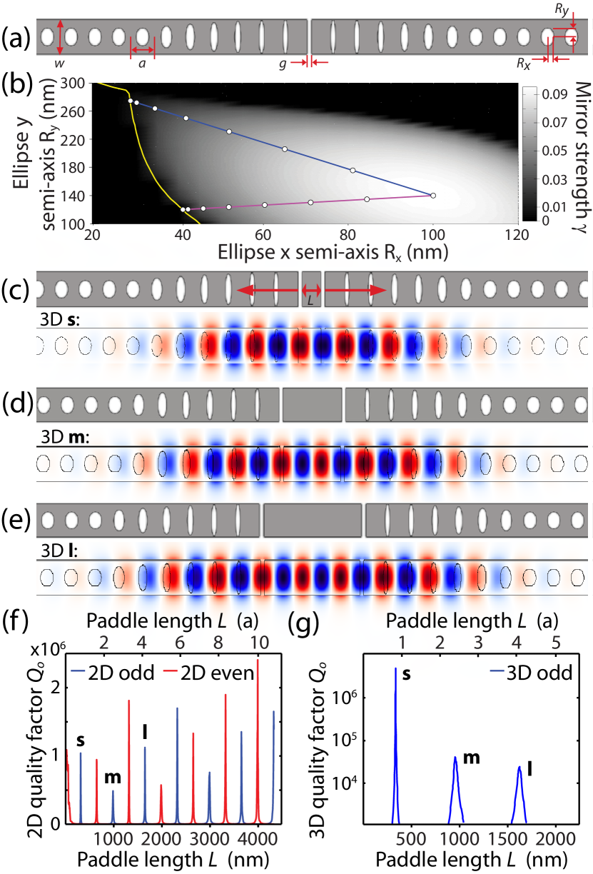
To create a paddle nanocavity, the split-beam cantilevers are separated and an unpatterned dielectric block of length with the nominal waveguide cross-section is inserted between them, as shown in Fig. 2(c). As three-dimensional (3D) optical simulations can be time consuming Quan, Deotare, and Loncar (2010), parameter searches in two-dimensions (2D) are first used to target optical modes with high- within a chosen frequency range, followed by 3D simulations to optimize parameters. We take advantage of the three-fold symmetry of the structure to reduce the computation time, as we are interested in the lowest-frequency TE-like (-odd, -even) optical mode eigenfrequencies. To compensate for the lack of vertical confinement in the 2D simulations, a reduced effective index is used for silicon such that the eigenfrequencies of 2D simulations roughly match 3D results. Figure 2(f) shows the results of 2D simulations of the even and odd symmetry modes for paddle length varying with high resolution ( points). is found to oscillate as a function of , with high- values spaced in by integer wavelengths for a given symmetry. This is consistent with the result of Quan et al.Quan, Deotare, and Loncar (2010) for an unpatterned waveguide capped by photonic crystal mirrors.
In a realistic device, the paddle needs to be suspended by supports connected to the surrounding chip. To minimize radiation loss introduced by the supports, they should be connected to the paddle at a node of the nanocavity field. Hence, we only consider the odd optical modes of devices with supports connected to the paddle center. As many quantum optical and optomechanical figures of merit scale with , where is the optical cavity mode volume defined by the peak field strength, we focus on the three smallest values of supporting high- modes: = 334 nm, 1006 nm, and 1670 nm, which we label as small (), medium () and large () paddle lengths respectively. Figure 2(g) shows the predicted interpolated from approximately fifty 3D FDTD simulations in the neighbourhood of each targeted , for a paddle nanocavity without supports. We find high- peaks at values in close agreement with predictions from the 2D simulations in Fig. 2(f). For the , and paddle nanocavities, as shown in Fig. 2(c),(d) and (e), we find 3D simulated 3.53, 3.43, and 1.72 for paddle lengths 334 nm, 964 nm, and 1604 nm respectively, all at 1584 nm. The corresponding electric field profiles for these nanocavities are plotted in Fig. 2(c-e), and show that the optical modes are tightly confined within the tapered hole region and overlap with the paddle.
The smallest nominal hole semi-minor axes of nm in the design used above are challenging to fabricate. Using the fabrication process discussed below, we can consistently realize holes with (, ) (40, 100) nm. To design a ‘fabricable’ device within this constraint, we designed a paddle nanocavity tapering from central hole dimensions of (41.2, 120) nm, with the resulting hole dimensions and shown in Fig. 2(b). As before, we replace the central hole with a paddle of length from the optimized design above, separated from the cantilevers by 50 nm gaps. The resulting structure is shown schematically in Fig. 1(a). Without supports and before optimization, the simulated quality factor of this design is . To realize a suspended paddle, we add 100 nm wide, 1.5 m long centre supports. The resulting increases to . This indicates that for this design, scattering from the supports does not limit , and that from the ideal design is not optimal for the supported fabricable structure. After re-optimizing , we find to be within simulation uncertainty of of the optimized device without supports. The simulated electric field profile of this device is shown in Fig. 1(b).
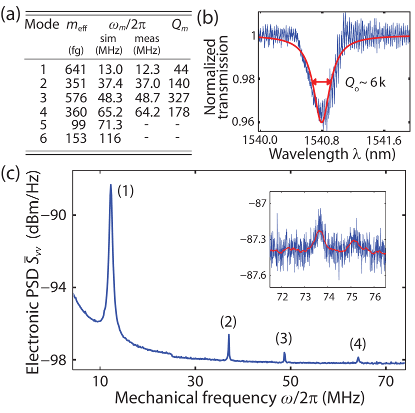
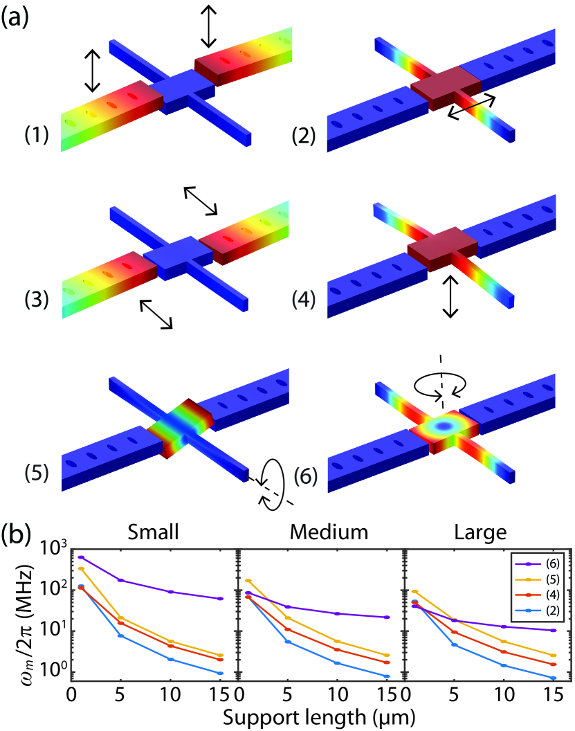
The mechanical properties of the device, in particular , are also affected by the paddle and support design. Figure 3(a) shows six mechanical resonance displacement profiles, labeled (1)-(6), calculated using a finite element simulation (COMSOL) of the fabricable device. Resonances (1) and (3) are characterized by the cantilevers moving up and down, and side-to-side, respectively. Resonances (2), (4), (5) and (6) involve the paddle moving in-plane along the device axis, up-and-down, torsionally, and rotationally, respectively. We liken the axial motion of resonance (2) to the membrane-in-the-middle scheme, and note that the torsional resonance could be useful for sensing applications, for example in torque magnetometry Losby et al. (2012). The resonance frequencies as a function of support length (100 nm support width) for the paddle modes are shown in Fig. 3(b), indicating that can be tuned by several orders of magnitude. Figure 4(a) tabulates for each mode. As a result of the wavelength-scale dimensions of the paddle, are sub-pg, with the torsional mode exhibiting the smallest .
To experimentally study paddle nanocavities, we fabricated devices from 220 nm thick silicon-on-oxide (SOI). SOI chips were coated with ZEP-520A resist, the design pattern was exposed with a 30 keV Raith 150-Two electron beam lithography system, and was transferred to the Si-layer with a C4F8/SF6 reactive ion etch. The sacrificial 3 m thick silicon oxide layer was selectively removed using hydrofluoric acid, creating suspended devices. Figure 1(c-e) shows SEM images of a typical device (type ). Note the measured gap width and paddle length in Fig. 1(e) are approximately 55 nm and 898 nm respectively, which are within 10% of the nominally designed values.
A dimpled, near-field fiber taper probe was used to test the paddle nanocavities Hryciw et al. (2015). Light from a tunable diode laser (New Focus Velocity) at 1541 nm was input to the fiber taper evanescently coupled to the device. The fiber was positioned using 50 nm resolution stepper motor stages either hovering above the paddle, or contacting one of the cantilevers. All measurements were performed under ambient conditions. The transmitted light was split using a 10:90 fiber coupler, with the outputs detected using low- (Newport 1623) and high-bandwidth (Newport 1811) detectors. Detector signals were monitored with a data acquisition card and a real-time spectrum analyzer (Tektronix RSA 5106A) for investigating the optical mode and mechanical resonances, respectively. The spectrum in Fig. 4(b) shows the fiber taper transmission as a function of wavelength when the dimpled fiber is contacting a paddle nanocavity cantilever. A dip in transmission characteristic of evanescent coupling to the nanocavity optical mode is observed, with a linewidth corresponding to . The electronic power spectral density (PSD) measured by the RSA when the laser wavelength is fixed within this linewidth is shown in Fig. 4(c). Four peaks resulting from optomechanical transduction of the thermally-driven paddle resonances were clearly observed, with frequencies closely matching the simulated of the fabricated structure, as tabulated in Fig. 4(a). Also tabulated are the measured mechanical quality factors, , of these resonances. For the measurements shown here, the low- are a result of viscous damping from the ambient environment. Two other low signal-to-noise mechanical resonances were also observed near 74 MHz, shown in the inset to Fig. 4(c). One peak is expected to be the torsional resonance (5), and the other a nonlinear harmonic of the axial sliding resonance (2) Kaviani et al. (2015); Doolin et al. (2014). Although paddle nanocavities are completely symmetric in design and in theory have no intrinsic linear optomechanical coupling Johnson et al. (2002); Kaviani et al. (2015), fabrication imperfections and fiber-induced dissipative and dispersive optomechanical coupling Hryciw et al. (2015) enable the observed optomechanical transduction. The nature of this coupling requires further measurements of the wavelength and fiber position dependence of the observed signal Wu et al. (2014).
Enhancements to the optomechanical measurement sensitivity could be realized by operating under vacuum conditions to increase by several orders of magnitude Svitelskiy et al. (2012). Combined with adjusting the support dimensions to lower to increase the thermal amplitude of the resonances, these improvements will allow higher signal-to-noise measurements, and may allow unambiguous discrimination of the torsional mode. These changes would also benefit characterization of nonlinear optomechanical coupling, whose signal strength scales with . This is of particular interest since analysis by Kaviani et. al Kaviani et al. (2015) of devices predict a quadratic optomechanical coupling coefficient MHz/nm2, and a single photon to two phonon optomechanical coupling rate Hz, well above the rates observed in similar systems Lee et al. (2014); Doolin et al. (2014). We have also predicted that the and designs have of 100 and 550 MHz/nm2, respectively. Future nonlinear quantum optomechanics experiments, for example observation of phonon shot noise Clerk, Marquardt, and Harris (2010), are predicted to be possible using optimized paddle nanocavity devices Kaviani et al. (2015). In addition to improving , reducing fabrication imperfections and increasing minimum features sizes to increase are necessary to realize such experiments.
In conclusion, we have systematically designed and experimentally demonstrated a high- paddle nanocavity, and observed optomechanical transduction of thermomechanical motion of several resonances of this device with fg effective mass. These devices are promising for future applications including torque magnetometry Losby et al. (2012), nanomechanical sensing Aspelmeyer, Kippenberg, and Marquardt (2014), and nonlinear optomechanics.
We thank the staff of the nanoFAB facility at the University of Alberta and at the National Institute for Nanotechnology for their technical support. This work was funded by the National Research Council Canada (NRC), Natural Science and Engineering Research Council of Canada (NSERC), the Canada Foundation for Innovation (CFI) and Alberta Innovates Technology Futures (AITF).
References
- Aspelmeyer, Kippenberg, and Marquardt (2014) M. Aspelmeyer, T. J. Kippenberg, and F. Marquardt, Rev. Mod. Phys. 86, 1391 (2014).
- Favero and Marquardt (2014) I. Favero and F. Marquardt, New Journal of Physics 16, 085006 (2014).
- Eichenfield et al. (2009a) M. Eichenfield, J. Chan, R. Camacho, K. Vahala, and O. Painter, Nature 462, 78 (2009a).
- Eichenfield et al. (2009b) M. Eichenfield, R. Camacho, J. Chan, K. J. Vahala, and O. Painter, Nature 459, 550 (2009b).
- Metcalfe (2014) M. Metcalfe, Applied Physics Reviews 1, 031105 (2014).
- Arcizet et al. (2006) O. Arcizet, P.-F. Cohadon, T. Briant, M. Pinard, A. Heidmann, J.-M. Mackowski, C. Michel, L. Pinard, O. Français, and L. Rousseau, Phys. Rev. Lett. 97, 133601 (2006).
- Li, Pernice, and Tang (2009) M. Li, W. H. P. Pernice, and H. X. Tang, Nat. Nano. 4, 377 (2009).
- Anetsberger et al. (2010) G. Anetsberger, E. Gavartin, O. Arcizet, Q. P. Unterreithmeier, E. M. Weig, M. L. Gorodetsky, J. P. Kotthaus, and T. J. Kippenberg, Phys. Rev. A 82, 061804 (2010).
- Krause et al. (2012) A. G. Krause, M. Winger, T. D. Blasius, W. Lin, and O. Painter, Nat. Photon. 6, 768 (2012).
- Liu et al. (2012) Y. Liu, H. Miao, V. Aksyuk, and K. Srinivasan, Opt. Express 20, 18268 (2012).
- Wu et al. (2014) M. Wu, A. C. Hryciw, C. Healey, D. P. Lake, H. Jayakumar, M. R. Freeman, J. P. Davis, and P. E. Barclay, Phys. Rev. X 4, 021052 (2014).
- Chan et al. (2011) J. Chan, T. P. M. Alegre, A. H. Safavi-Naeini, J. T. Hill, A. Krause, S. Groblacher, M. Aspelmeyer, and O. Painter, Nature 478, 89 (2011).
- Safavi-Naeini et al. (2013) A. H. Safavi-Naeini, S. Gröblacher, J. T. Hill, J. Chan, M. Aspelmeyer, and O. Painter, 500, 185 (2013).
- Sankey et al. (2010) J. C. Sankey, C. Yang, B. M. Zwickl, A. M. Jayich, and J. G. E. Harris, Nature Phys. 6, 707 (2010).
- Flowers-Jacobs et al. (2012) N. Flowers-Jacobs, S. Hoch, J. Sankey, A. Kashkanova, A. Jayich, C. Deutsch, J. Reichel, and J. Harris, Applied Physics Letters 101, 221109 (2012).
- Karuza et al. (2013) M. Karuza, M. Galassi, C. Biancofiore, C. Molinelli, R. Natali, P. Tombesi, G. Di Giuseppe, and D. Vitali, Journal of Optics 15, 025704 (2013).
- Doolin et al. (2014) C. Doolin, B. Hauer, P. Kim, A. MacDonald, H. Ramp, and J. Davis, Physical Review A 89, 053838 (2014).
- Brawley et al. (2014) G. Brawley, M. Vanner, P. Larsen, S. Schmid, A. Boisen, and W. Bowen, arXiv:1404.5746 (2014).
- Paraïso et al. (2015) T. K. Paraïso, M. Kalaee, L. Zang, H. Pfeifer, F. Marquardt, and O. Painter, arXiv:1505.07291 (2015).
- Thompson et al. (2008) J. D. Thompson, B. M. Zwickl, A. M. Jayich, F. Marquardt, S. M. Girvin, and J. G. E. Harris, Nature 452, 72 (2008).
- Gangat, Stace, and Milburn (2011) A. A. Gangat, T. M. Stace, and G. J. Milburn, New Journal of Physics 13, 043024 (2011).
- Clerk, Marquardt, and Harris (2010) A. A. Clerk, F. Marquardt, and J. G. E. Harris, Phys. Rev. Lett. 104, 213603 (2010).
- Bhattacharya, Uys, and Meystre (2008) M. Bhattacharya, H. Uys, and P. Meystre, Physical Review A 77, 033819 (2008).
- Nunnenkamp et al. (2010) A. Nunnenkamp, K. Børkje, J. G. E. Harris, and S. M. Girvin, Phys. Rev. A 82, 021806 (2010).
- Biancofiore et al. (2011) C. Biancofiore, M. Karuza, M. Galassi, R. Natali, P. Tombesi, G. Di Giuseppe, and D. Vitali, Physical Review A 84, 033814 (2011).
- Kaviani et al. (2015) H. Kaviani, C. Healey, M. Wu, R. Ghobadi, A. Hryciw, and P. E. Barclay, Optica 2, 271 (2015).
- Hryciw and Barclay (2013) A. C. Hryciw and P. E. Barclay, Opt. Lett. 38, 1612 (2013).
- Quan, Deotare, and Loncar (2010) Q. Quan, P. Deotare, and M. Loncar, App. Phys. Lett. 96, 203102 (2010).
- Quan and Loncar (2011) Q. Quan and M. Loncar, Opt. Express 19, 18529 (2011).
- Oskooi et al. (2010) A. F. Oskooi, D. Roundy, M. Ibanescu, P. Bermel, J. Joannopoulos, and S. G. Johnson, Comp. Phys. Comm. 181, 687 (2010).
- Losby et al. (2012) J. Losby, J. Burgess, Z. Diao, D. Fortin, W. Hiebert, and M. Freeman, J. Appl. Phys. 111, 07D305 (2012).
- Hryciw et al. (2015) A. C. Hryciw, M. Wu, B. Khanaliloo, and P. E. Barclay, Optica 2, 491 (2015).
- Johnson et al. (2002) S. G. Johnson, M. Ibanescu, M. A. Skorobogatiy, O. Weisberg, J. D. Joannopoulos, and Y. Fink, Phys. Rev. E 65, 066611 (2002).
- Svitelskiy et al. (2012) O. Svitelskiy, V. Sauer, D. Vick, K.-M. Cheng, N. Liu, M. R. Freeman, and W. K. Hiebert, Phys. Rev. E 85, 056313 (2012).
- Lee et al. (2014) D. Lee, M. Underwood, D. Mason, A. Shkarin, S. Hoch, and J. Harris, arXiv:1401.2968 (2014).