Independent Study Option report, April 2015
\ArchiveMSc in Computing (Spec. in Artificial Intelligence)
Imperial College London
\PaperTitleCentral Pattern Generators
for the control of robotic systems
\PaperTitleNoLineBreaksCentral Pattern Generators for the control of robotic systems
\AuthorsAuthor: Carlos Garcia-Saura
Supervisor: Prof. Murray Shanahan
\KeywordsBio-inspiration, Robotics, Neuron-based oscillators, Computational models, Distributed motion control
\Abstract
Bio-inspired control of motion is an active field of research with many applications in real world tasks. In the case of robotic systems that need to exhibit oscillatory behaviour (i.e. locomotion of snake-type or legged robots), Central Pattern Generators (CPGs) are among the most versatile solutions. These controllers are often based on loosely-coupled oscillators similar to those found in the neural circuits of many animal species, and can be more robust to uncertainty (i.e. external perturbations) than traditional control approaches.
This project provides an overview of the state-of-the-art in the field of CPGs, and in particular their applications within robotic systems. The project also tackles the implementation of a CPG-based controller in a small 3D-printed hexapod.
Introduction
We live in an exciting time for robotics. The computing revolution that made powerful processing technology widespread, has contributed to the rise of domestic 3D printers, and being able to manufacture customized structures at a low cost, actuate them with off-the-shelf hardware, and control them with computers, has proven to be a winning combination for robotics. New designs keep appearing each day, in many occasions taking inspiration from nature; this is the case of snake-type or legged robots, among others.
But biologically-inspired robots often have many degrees of freedom that present as a true challenge for traditional control approaches (i.e. centralized systems that compute motion patterns globally and control an articulated robot at the joint level)[1]. Whilst it is possible to solve some of those problems for controlled environments, many algorithms are simply not prepared for the real world[2, 3]. It is here where neuroscience is answering many questions, and we are starting to see real world robots that not only look like, but also interact with the environment just as living creatures do.
The mechanisms behind higher level motion planning in animals -cognition- have been a subject of research for many decades, but the exact way in which the brain operates is yet a subject of speculation. What we know is that evolution has developed efficient ways to abstract very complex locomotion patterns, and turn them into simple control signals that can be effortlessly handled by the brain[1, 2, 3]. Given the intrinsic periodicity of locomotion, it is reasonable to think that neural circuits do not need to explicitly control the position of every articulation, but rather modulate higher level parameters such as the amplitude or frequency of each gait[4, 5].
Often involved in motion control, Central Pattern Generators (CPGs) are biological neural networks that produce rhythmic output patterns without the need for sensory feedback. This means that either individual neurons or the way they are connected to each other, can lead to oscillatory dynamics that are useful for various biological functions (i.e. walking gaits, respiration, or even circadian rhythms). These oscillatory neural circuits have been studied in many animals such as stick insects and cockroaches[6], sea angels[7], fish[2, 8] and other vertebrates such as the salamander[4], cats[9] and mice[10]. In the case of vertebrates, CPG circuits involved in locomotion are often situated in the spinal cord.
These pattern-generating neural networks as observed in biology have inspired roboticists, and it has already been possible to replicate locomotion behaviours in many robot designs. Some examples are the salamander-inspired Pleurobot[4] from EPFL, quadrupeds like Lynx[9] from the same university, the worm-like Cube Revolutions[5] from Univ. Autonoma de Madrid, or the stick-insect robot Hector[11] from Bielefeld University.
1 Computational Models of CPGs
Controllers based on central pattern generators can indeed be very robust against uncertainties in the environment (i.e. autonomous stepping over an obstacle that appears in the way)[12], but whenever a robot needs to interact with the real world, delays in its response may still have dramatic consequences. Thus, real time decision-making is crucial for these sort of interactions, so detailed simulations of biologically realistic CPGs (i.e. spiking networks of Hodgkin-Huxley neurons) are frequently deemed too computationally intensive for robot control. Rather, simplified models of CPGs have been developed in order to facilitate their real-world implementation and to meet those strict timing requirements.
1.1 Biological Neural Networks
In this section we are going to focus on CPG implementations that remain close to biology by modelling the dynamics of neural networks for motion control.
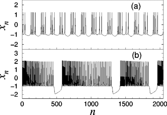
The first model that we are going to study is the Rulkov map type neuron. Whilst they are more efficient to compute than continuous time models, these neurons can still exhibit rich spiking dynamics (see Fig. 1) that allow for implementations of central pattern generators that closely resemble data from experiments with real ganglia[13].
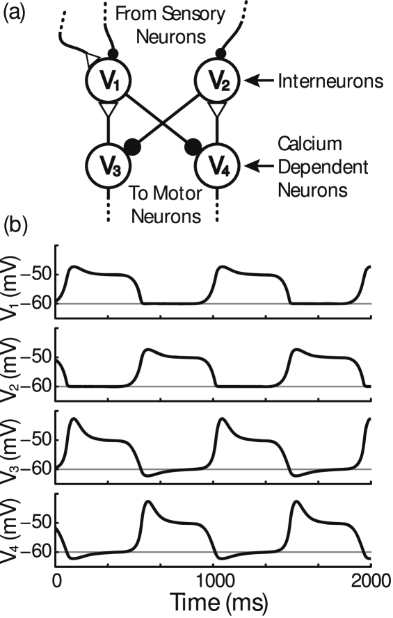
The basic unit of a biological CPG is the half-centre, which consists in two neurons (or populations) that cannot generate rhythmic activity by themselves, but may oscillate when coupled reciprocally (see Fig. 2).
A half-centre is said to work in escape mode if the off neuron turns on after escaping from inhibition, and similarly, the release mode means that the neurons turn on after being released from inhibition. Variations in the properties of each synapse can produce very different coalition results in a broad range: from the complete synchrony of firings (in counter-phase or coherent phase) to completely decoupled oscillations[1, 2, 3, 14, 15].
In legged systems, for example, flexion and extension of a joint should never occur simultaneously. We can achieve this by using pairs of CPG half-centres coupled in anti-phase to control them (see Fig. 3). As in nature, flexor and extensor muscles alternate to achieve full oscillatory patterns.
We have already seen the Rulkov map, but another neuron model that has been used in plenty of research in this field is the leaky integrator type. This non-spiking model is based on a set of differential equations that are capable of representing either individual non-spiking inter-neurons or the firing rate of a population[6, 10, 16].
1.1.1 Controlling locomotion with synaptic gating
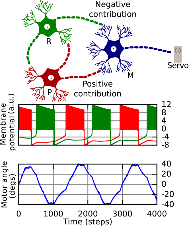
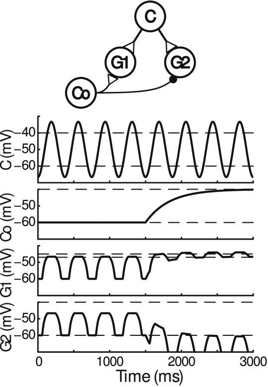
Coupling between CPGs is often achieved with the direct excitation/inhibition of neurons between each oscillatory source. Synaptic gating, however, allows for richer interactions, as it provides neurons with the ability to dynamically alter the strength of some other synapse within the network. This means that it can either facilitate or suppress the communication between two other neurons. An example implementation that demonstrates this effect is shown in Figure 4.
These methods make it possible to achieve a wide range of modulations in the locomotive patterns produced by a biological neural network[1, 2, 6]:
-
•
The frequency of oscillation can be controlled by varying the input current for neurons within a CPG half-centre.
-
•
Gating the output of the CPG allows for amplitude-controlled oscillations.
-
•
Also, an asymmetric modulation of the couplings between two half-centres can produce variations of the duty cycle.
There are many examples of real-world robots that use CPG implementations based on biological neural networks. The Rulkov map neuron model has been demonstrated for the control of snake-type robots[14, 17] as well as in robots with limited wheels that move by means of oscillations[18]. The leaky integrator neuron model has been used in robot controllers for quadrupeds[10] and insects[16].
1.2 Coupled oscillator networks
Another approach towards the implementation of central pattern generators in robots is to move away from biology, and make use of mathematical models of synchrony such as the Kuramoto oscillators. Rather than trying to explain rhythmogenesis, these models focus on the study of the effects of inter-oscillator couplings, and assume the presence of underlying oscillatory mechanisms.
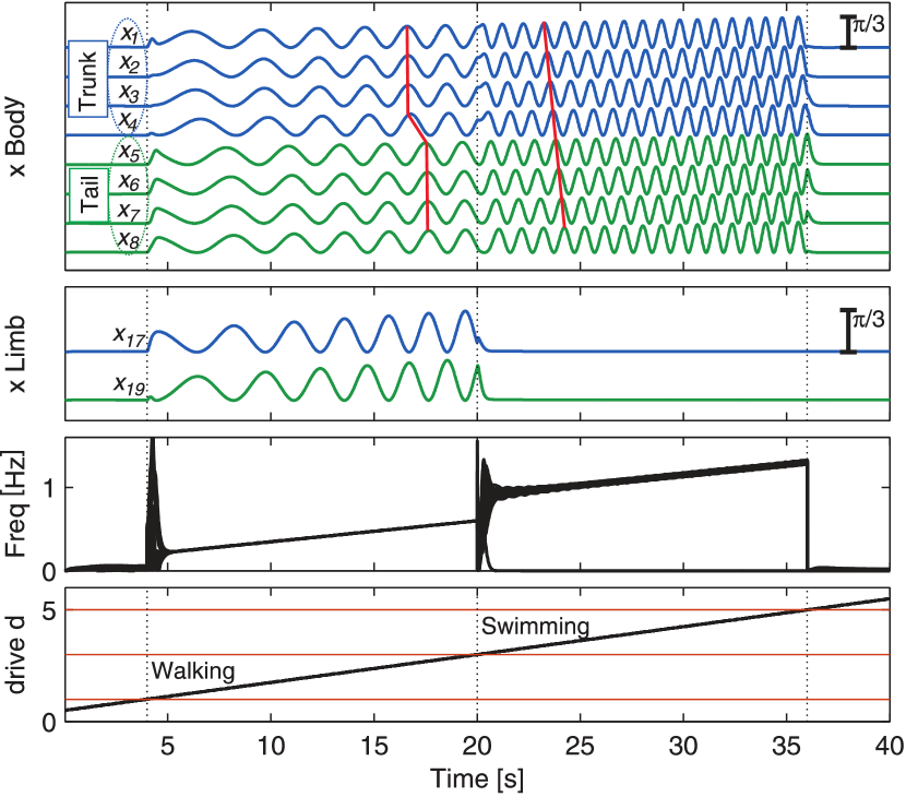
Even though the models are simple, it is still possible to replicate many of the characteristics that appear in nature. For instance, Salamandra robotica from EPFL (see Figs. 5 & 6) successfully demonstrated a smooth transition between the walking and swimming gaits[4].
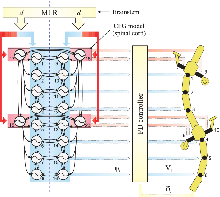
The controller of Salamandra robotica is very interesting indeed, as it was built upon four biological hypotheses:
-
1.
The salamander has a body CPG that spontaneously produces traveling waves (swimming gait) such as the one produced by the lamprey[2] when activated with a tonic drive signal.
-
2.
Limb CPGs have lower intrinsic frequencies than the segments or body oscillators.
-
3.
When the limb CPG is activated, it forces the whole system into walking mode. To achieve this, couplings are kept stronger than interconnections.
-
4.
Limb CPGs cannot oscillate at high frequencies, so they saturate at high levels of drive. The natural swimming gait can then take over control.
Altogether, the resulting controller can efficiently actuate two different gaits in a 10 DOF robot with only one input signal (see Fig. 6). The direction of locomotion can also be controlled with an additional input signal that modulates the oscillations of each side of the spinal cord.
For this study we wanted to better understand how these oscillator networks worked at a lower level, but the ten degrees of freedom of the salamander robot discouraged a re-implementation. Instead, we found another project from the same laboratory: a fish robot with three degrees of freedom (see Fig. 7).
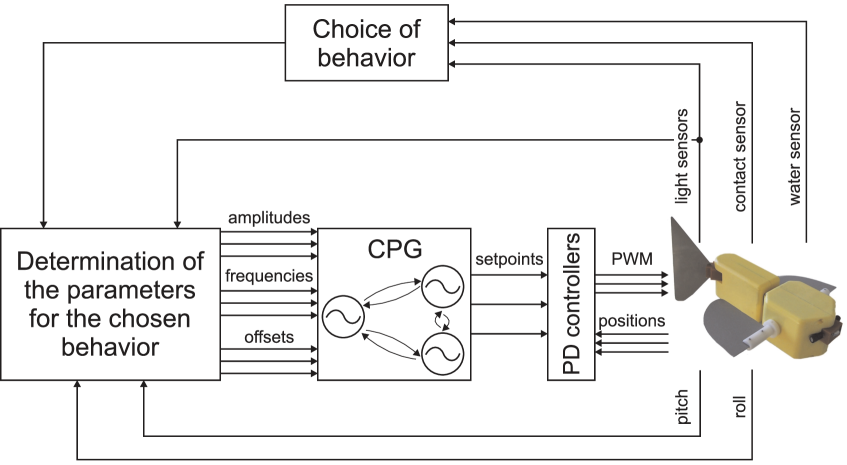
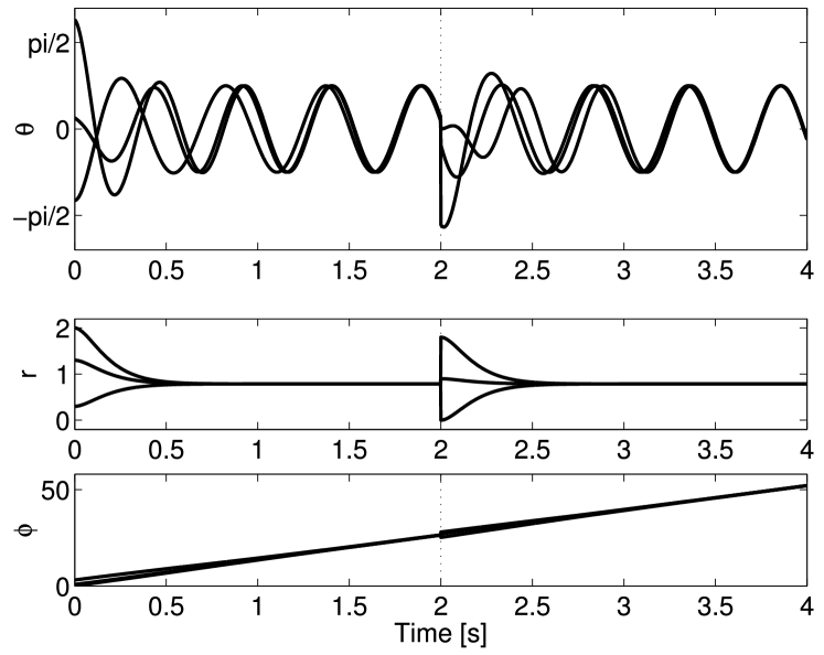
The CPG model for the fish robot is indeed much more simple than the one of the salamander, but on the other hand it can show in a more intuitive way basic concepts such as oscillation coupling and rhythm negotiations (see Fig. 8).
1.3 Incorporation of sensory feedback
In the case of the fish robot, sensory feedback was incorporated by directly modulating the parameters within the CPG according to predefined gaits. For instance, the fish robot has two light intensity sensors, one on each side, that were used to achieve a photo-taxis behaviour with a Braitenberg vehicle approach[8] (the oscillation of each pectoral fin is modulated by the light intensity perceived in the opposite side; this has the effect of the robot turning towards light sources in the environment).
Whilst such an approach can work well for simple neural networks, a more interesting and biologically realistic method would incorporate sensory information by encoding system-wide behavioural reflexes into the network itself.
For instance, lets recall that both the salamander and fish robot rely on PD controllers that ensure that each motor joint reaches a target angle, calculated by the pattern-generating network. Those PD controllers are indeed using information from rotation encoders at the joint level, so why not directly incorporate that information into the CPG instead? In nature, this simple form of sensory feedback is at the muscular level, where strech or edge cells can sense muscle contractions, and feed them back into the network. In humans, these cells play a very important role in the spatial perception of the body (proprioception). This approach is also much more robust against uncertainty in external perturbations than open loop CPG controllers.
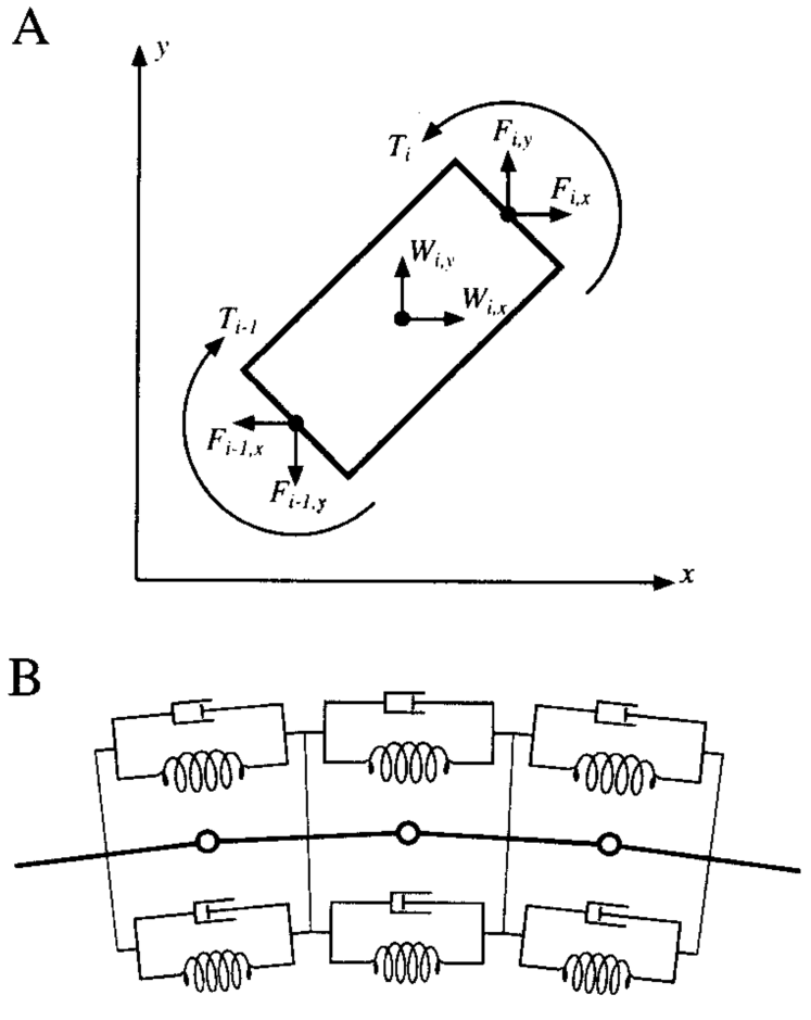
However, until very recently this feedback concept could not be exploited in real robots due to the elevated cost of high precision rotatory encoders. Instead, virtual stretch cell models (such as the linear Hill muscle model) were developed in order to achieve realistic neuro-mechanical simulations. This concept is discussed in Figure 9.
Other simple forms of sensory feedback are foot contact sensors. Recent studies have shown that hair fibres present in the feet of rats (carpal vibrissae) behave as contact sensors that influence the kinematics of locomotion[20]. Whilst the incorporation of such feedback into CPG networks is far from trivial, these kind of sensors have the advantage of greater simplicity and lower implementation cost than rotatory encoders.
The last sensory input related to locomotion that deserves a mention is the vestibular system. Placed in the inner ear of most mammals, it plays an essential role in balance. One of the best examples is bipedal walking, where equilibrium perception is seamlessly incorporated into the neural mechanisms responsible for motion control. CPG-based robot controllers can also benefit from this form of input by using off-the-shelf accelerometers.
As a final remark for this section, we must say that CPGs often have many parameters that need to be finely adjusted in order to achieve an efficient locomotion. The automatic entrainment of these models is still a subject of research[21, 22, 23].
Though there is plenty of software available for the simulation of robots, only few combine environment physics with neuron dynamics. The free version of AnimatLab111http://animatlab.com/ provides a nice toolbox for basic experimentation, but more powerful open-source tools such as neuroConstruct222http://www.neuroconstruct.org/ and geppetto333http://www.geppetto.org/ are being developed thanks to the efforts of the OpenWorm444http://www.openworm.org/ project.
2 Experiments with a 3 DOF hexapod
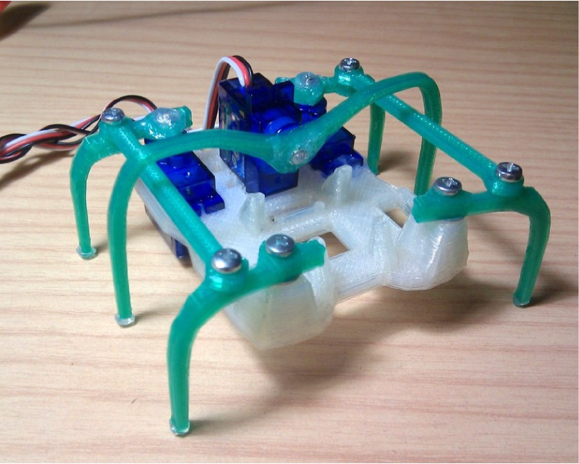
For the experimental part of this study, we decided to implement a CPG controller for a small 3D-printed hexapod robot555Originally designed by Ijon Tichy:
http://www.thingiverse.com/thing:5156/ (see Fig. 10).
Since it has three degrees of freedom, it was the perfect candidate for a re-implementation of the controller presented in “Controlling swimming and crawling in a fish robot using a central pattern generator” by A. Crespi et al.[8]
Our motivation for using the fish model as a reference implementation was that its oscillatory network model is very similar to the one employed in Salamandra robotica[4] from EPFL. With three degrees of freedom instead of ten, the fish robot seemed like a better choice as a didactic exercise.
The CPG is built upon amplitude-controlled phase oscillators derived from the Kuramoto model of synchrony. Next, we will show the set of differential equations that define the network:
| (1) |
| (2) |
| (3) |
| (4) |
Where:
-
•
is the output angle of each oscillatory centre
-
•
, and are the state variables that encode the variation in time of every phase, amplitude and offset
-
•
The control parameters for each oscillator are (natural frequency), (target amplitude) and (target offset).
- •
-
•
Finally, and are respectively the coupling weights and phase biases that determine how oscillator influences oscillator .
The only change we made to the original equations in [8] was to replace the cosine function in Eqn. (4) with a sine. That way, the reference positions of the joints in the hexapod robot -corresponding to zero offset- match with the lateral segments being perpendicular to the body, and with a flat position of the middle segment (the same posture as in Fig. 10).
Equations (2) and (3) are critically-dampened second-order differential equations with stable fix points and respectively. With them it is possible to smoothly modulate the amplitude and offset of the oscillations in real time.
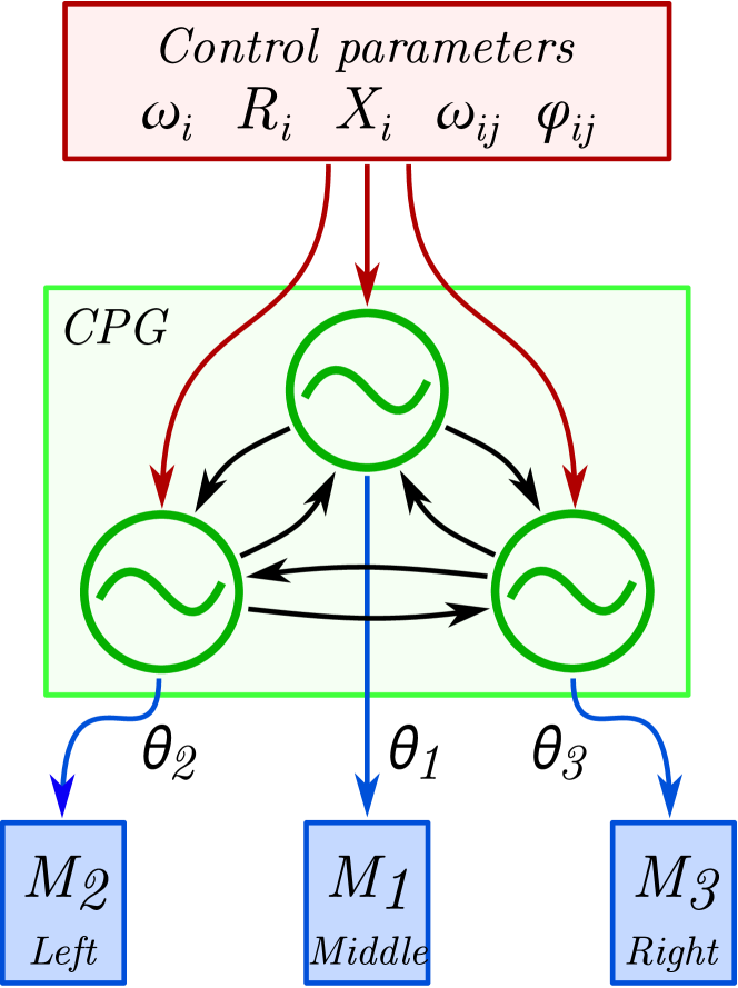
The three oscillators correspond to the middle, left and right joints of the robot respectively, for which the maximum oscillation amplitudes are , . A schematic diagram with the employed topology is shown in Figure 11.
As in Crepi’s article, each of the three oscillators were set to the same natural frequencies (). Initially, the coupling parameters were set to:
, ,
, .
In other words: the network is fully connected, but there are no self-couplings, and (originally) no phase biases. With these parameters, the system converges into a regime where the phases (state variables ) grow linearly with a common rate and zero phase difference between the oscillators.
For the robot hexapod, gait information would need to be encoded into the phase biases . Since the original paper was instead modulating the target offsets and amplitudes , our model used exclusively as a smooth transition between the static state (zero amplitude or ) and motion, and was not necessary.
With this topology it is possible to define the following walking gaits:
-
•
Forward walking is achieved by setting
, otherwise,
, ,
-
•
Backward walking simply requires a shift in the phase couplings:
, otherwise,
, ,
-
•
Clockwise rotation is achieved with
, otherwise,
, ,
-
•
Finally, counter-clockwise rotation uses
, otherwise,
, ,
2.1 Implementation of the CPG with Arduino
The robot is controlled using a a ZUM BT-328 board666http://www.bq.com/gb/placa-zum-bt/, which is based on the Arduino777http://www.arduino.cc/ platform. The ordinary differential equations of the oscillator model were implemented using the Euler method888https://en.wikipedia.org/wiki/Euler_method, with the following update rule:
Where is the time step for the Euler method. In our setup, we used a value of .
3 Results and Discussion
The hexapod implementation was a very useful test-bed for its simplicity, and we could experiment with a wide variety of parameters. For instance, we set so that the legs at both sides of the robot negotiated a counter-phase rhythm. Locomotion was then achieved by coupling one of the sides uni-directionally with the middle segment (, , ).
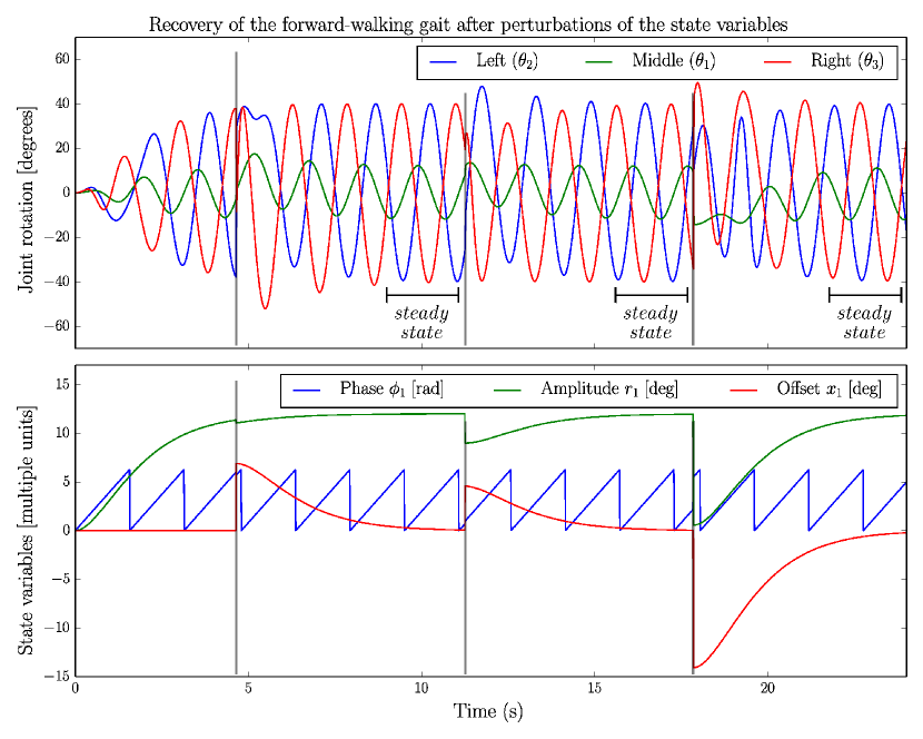
Another effect that we evaluated was the ability of the CPG to synchronize even when each oscillator had a different natural frequency. In a centralized approach with no couplings, slight variations of the intrinsic frequencies can lead to inconsistency in the gaits over time, due to phase drift. We could observe instead how the CPG corrected those slight phase differences seamlessly in real time, even after perturbations had been applied to the state variables (see Fig. 12).
3.1 Smooth transitions between gaits
We also tried to achieve a similar gait transitioning effect as the one in the salamander robot[4]. By setting different natural frequencies for each oscillator, our intention was to create multiple resonant states (gaits) that arised at different levels of drive. At low frequencies the robot would for instance rotate in place, but upon a frequency increase a new forward gait would be negotiated among oscillators. Unfortunately we were not able to make this work, so more experimentation (i.e. the incorporation of additional oscillators into the network) would be needed.
Such a topologically-based control approach would not only be more realistic in biological terms, but also more interesting in regards to sensory input management. For instance, joint-level feedback would allow to detect collisions with obstacles in the ground, eliciting obstacle-avoidance behaviour and thus producing a more efficient locomotion.
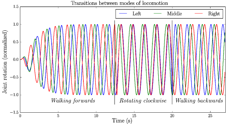
Rather than using a topological control approach, we achieved smooth transitions between each gait using the same method as in the fish robot paper[8]. It basically employs the stability properties of CPG networks to automatically negotiate oscillations after abruptly changing their coupling parameters (see Fig. 13). This is a very simple method, but it demonstrates the flexibility of CPGs for both high-level and low-level motor controller implementations.
3.2 Concluding remarks
Evolution has developed biological neural networks with pattern-generating properties (CPGs) as an abstraction that facilitates efficient locomotive behaviour in animals. Scientific research has later developed methods to employ such abstractions in real-world problems.
This project has studied the applications of artificial central pattern generators in the field of robotics. The state-of-the-art has been reviewed, and the most useful techniques have been shown, together with examples of their applications in real world robots. The project has also tackled the implementation of a CPG-based controller in an hexapod with 3 degrees-of-freedom, and successfully demonstrated its ability to smoothly transition between various walking gaits. The robustness of the CPG has also been evaluated against random perturbations in the environment (c.f. Figs. 12 & 13).
Bio-inspired controllers based on central pattern generators are already having a remarkable impact in robotics. Furthermore, given the latest advances in low-cost manufacture (a combination of 3D printing technology with of-the-shelf sensors and actuators), it will be very interesting to see what novel robot designs appear in the near future.
Acknowledgments
I would like to thank Professor Murray Shanahan for his constant enthusiasm in neuroscience and insightful advice for this project.
References
- [1] Auke Jan Ijspeert. Central pattern generators for locomotion control in animals and robots: A review. Neural Networks, 21(4):642 – 653, 2008. Robotics and Neuroscience.
- [2] Örjan Ekeberg. A combined neuronal and mechanical model of fish swimming. Biological Cybernetics, 69(5-6):363–374, 1993.
- [3] Scott L. Hooper. Central pattern generators. Current Biology, 10(5):R176 – R179, 2000.
- [4] Auke Jan Ijspeert, Alessandro Crespi, Dimitri Ryczko, and Jean-Marie Cabelguen. From swimming to walking with a salamander robot driven by a spinal cord model. Science, 315(5817):1416–1420, 2007.
- [5] F. Herrero-Carrón, F.B. Rodríguez, and P. Varona. Bio-inspired design strategies for central pattern generator control in modular robotics. Bioinspiration & Biomimetics, 6(1):016006, 2011.
- [6] MatthewA. Klein, NicholasS. Szczecinski, RoyE. Ritzmann, and RogerD. Quinn. Simulated neural dynamics produces adaptive stepping and stable transitions in a robotic leg. In Biomimetic and Biohybrid Systems, pages 166–177. 2014.
- [7] Y. I. Arshavsky, T. G. Deliagina, G. N. Orlovsky, Y. V. Panchin, L. B. Popova, and R. I. Sadreyev. Analysis of the Central Pattern Generator for Swimming in the Mollusk Clione. Annals of the New York Academy of Sciences, 860(1):51–69, November 1998.
- [8] Alessandro Crespi, Daisy Lachat, Ariane Pasquier, and AukeJan Ijspeert. Controlling swimming and crawling in a fish robot using a central pattern generator. Autonomous Robots, 25(1-2):3–13, 2008.
- [9] Peter Eckert, Alexander Spröwitz, Hartmut Witte, and Auke Ijspeert. Comparing the effect of different spine and leg designs for a small, bounding quadruped robot. 2014. Dynamic walking 2014, Zürich, June 10, 2014 – June 13, 2014.
- [10] Alexander Hunt, Manuela Schmidt, Martin Fischer, and RogerD. Quinn. Neuromechanical simulation of an inter-leg controller for tetrapod coordination. In Biomimetic and Biohybrid Systems, pages 142–153. 2014.
- [11] Axel Schneider, Jan Paskarbeit, Mattias Schaeffersmann, and Josef Schmitz. Hector, a new hexapod robot platform with increased mobility - control approach, design and communication. In Advances in Autonomous Mini Robots, pages 249–264. Springer Berlin Heidelberg, 2012.
- [12] Fernando Herrero-Carrón, Francisco B. Rodríguez, and Pablo Varona. Studying robustness against noise in oscillators for robot control. In International conference on automation, robotics and control systems, pages 58–63, July 2010.
- [13] Nikolai F. Rulkov. Modeling of spiking-bursting neural behavior using two-dimensional map. Physical Review E, 65(4):041922+, April 2002.
- [14] Fernando Herrero Carrón. Novel central pattern generator elements for autonomous modular robots. PhD thesis, Universidad Autónoma de Madrid, 2011.
- [15] Fernando Herrero-Carrón, Francisco de Borja Rodríguez Ortiz, and Pablo Varona. Dynamical invariants for cpg control in autonomous robots. In ICINCO (2), pages 441–445. INSTICC Press, 2010.
- [16] NicholasS. Szczecinski, JoshuaP. Martin, RoyE. Ritzmann, and RogerD. Quinn. Neuromechanical mantis model replicates animal postures via biological neural models. In Biomimetic and Biohybrid Systems, pages 296–307. 2014.
- [17] Joseph Ayers, Nikolai Rulkov, Dan Knudsen, Yong-Bin Kim, Alexander Volkovskii, and Allen Selverston. Controlling underwater robots with electronic nervous systems. APPLIED BIONICS AND BIOMECHANICS, 7(1):57–67, 2010.
- [18] I Urziceanu, F Herrero-Carrón, J Gonzalez-Gomez, M Nitulescu, F B Rodríguez, and P Varona. Central pattern generator control of a differential wheeled robot. In Int. Conference on System Theory, Control, and Computing (ICSTCC), pages 1–6, 2011.
- [19] Andre Rosendo, Xiangxiao Liu, Shogo Nakatsu, Masahiro Shimizu, and Koh Hosoda. A combined cpg-stretch reflex study on a musculoskeletal pneumatic quadruped. In Biomimetic and Biohybrid Systems, pages 417–419. 2014.
- [20] Thomas Helbig, Danja Voges, Sandra Niederschuh, Manuela Schmidt, and Hartmut Witte. Characterizing the substrate contact of carpal vibrissae of rats during locomotion. In Biomimetic and Biohybrid Systems, pages 399–401. 2014.
- [21] DavidJohan Christensen, Alexander Spröwitz, and AukeJan Ijspeert. Distributed online learning of central pattern generators in modular robots. In From Animals to Animats 11, pages 402–412. 2010.
- [22] Fernando Herrero-Carrón, FranciscoB. Rodríguez, and Pablo Varona. Flexible entrainment in a bio-inspired modular oscillator for modular robot locomotion. In Advances in Computational Intelligence, volume 6692 of Lecture Notes in Computer Science, pages 532–539. Springer Berlin Heidelberg, 2011.
- [23] Chengju Liu, Qijun Chen, and Danwei Wang. CPG-inspired workspace trajectory generation and adaptive locomotion control for quadruped robots. IEEE Trans Syst Man Cybern B Cybern, 41(3):867–880, June 2011.