Construction of a medium-sized Schwarzschild-Couder telescope as a candidate for the Cherenkov Telescope Array: development of the optical alignment system
Abstract:
The Cherenkov Telescope Array (CTA) is an international project for a next-generation ground-based gamma-ray observatory. CTA, conceived as an array of tens of imaging atmospheric Cherenkov telescopes, comprising small, medium and large-size telescopes, is aiming to improve on the sensitivity of current-generation experiments by an order of magnitude and provide energy coverage from 20 GeV to more than 300 TeV. The Schwarzschild-Couder (SC) medium-size candidate telescope model features a novel aplanatic two-mirror optical design capable of a wide field-of-view with significantly improved imaging resolution as compared to the traditional Davis-Cotton optics design. Achieving this imaging resolution imposes strict alignment requirements to be accomplished by a dedicated alignment system. In this contribution we present the status of the development of the SC optical alignment system, soon to be materialized in a full-scale prototype SC medium-size telescope at the Fred Lawrence Whipple Observatory in southern Arizona.
1 Introduction
The Schwarzschild-Couder medium-sized telescope (SC-MST) is a candidate telescope for the Cherenkov Telescope Array (CTA222www.cta-observatory.org, [1]), an international endeavor towards the construction of the next-generation of imaging atmospheric Cherenkov telescopes (IACTs). The SC-MST’s novel optics design offers a significantly better angular resolution over a wider field of view (FoV) than conventional single-mirror IACTs [2]. The SC-MST’s realization implies new technological challenges, like satisfying substantially more stringent optics alignment tolerances. This paper reports on the current development status of the SC-MST alignment system, soon to be materialized in a full telescope prototype unit (pSCT) which is now under construction at the Fred Lawrence Whipple Observatory in southern Arizona.
A more detailed description of the pSCT optical and mechanical systems as well as its gamma-ray camera, along with a study on the SC-MST potential contribution to the overall CTA performance can be found elsewhere in these proceedings [3, 4, 5, 6].
This contribution is structured as follows: in Section 2 we give a brief overview of the alignment system; in Section 3 we describe the development status of the global alignment system; the panel-to-panel alignment system is dealt with in Section 4; a short description of the alignment system software control is given in Section 5.
2 Overview of the pSCT alignment system
Primary mirror Secondary mirror Global alignment Value Value Translation to optical axis 10 mm 10 mm Translation to optical axis 17 mm 5 mm Tilt 15 mrad 0.15 mrad Panel-to-panel alignment Standard deviation Standard deviation Translation to optical axis 2.2 mm 1.1 mm Translation to optical axis 17mm 4 mm Rotation around tangent axis 0.1 mrad 0.2 mrad Rotation around radial axis 0.1 mrad 0.3 mrad Rotation around normal axis 16.2 mrad 118 mrad
The two-mirror SC optical system is designed to fully correct spherical and comatic aberrations while providing a large field of view and a fine plate-scale, allowing for finely pixelized focal plane instrumentation. To optimize production costs, the 9.7 m diameter primary mirror (M1) and the 5.4 m diameter secondary mirror (M2) are segmented into 48 and 24 mirror panels respectively. Extensive ray-tracing simulations of the SC-MST optical system indicated the need for sub-millimeter and sub-milliradian precision for both global and panel-to-panel alignments in order to achieve a point spread function (PSF) compatible with the pixel size of a high-resolution gamma-ray camera (see Table 1). In addition, the accuracy of source localization requires 5 arcsec mirror tilt control. These tolerances are roughly equivalent to a sub-mm radio telescope operating in the range 100 - 20 m and three to four orders of magnitude above the usual diffraction limit of optical telescopes. Nevertheless, these tolerances are far more demanding than those of current IACT optical systems and require automated mechanical alignment of the segmented mirror surfaces.
The global alignment system is designed to continuously measure relative positions of the main optical elements of the telescope, M1, M2 and the camera focal plane, as well as to detect large-scale spatial perturbations of the M1 and M2 figures. The panel-to-panel alignment system is designed to effectively detect and correct for misalignment between neighboring panels as well as to continuously monitor the alignment of the optical surfaces’ figures. The integration of both systems will ensure the aforementioned sub-millimeter and sub-milliradian precision in the alignment and positioning of the pSCT’s main optical elements.
3 Global alignment system
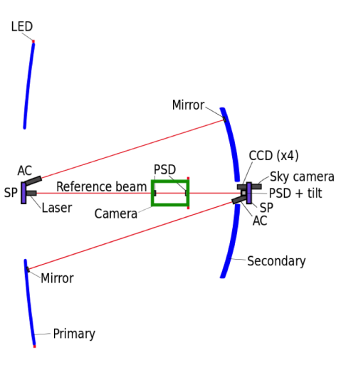
The global alignment system for the pSCT consists of CCD cameras imaging LEDs to measure the relative translations between M1, M2, and the gamma-ray camera, and autocollimators to measure the tilts of M1 and M2 (see Fig. 1, left panel, for a schematic view). Prototypes of all of the components have been built and tested.
The performance of the translation measurement system was tested as follows. A set of six LEDs were arranged on a panel in a configuration similar to what will be used on the pSCT. The LEDs were imaged with a CCD camera, roughly 8 meters away, which was moved along the line between the LED panel and the camera. An image was acquired at each position and the position of the LED panel was reconstructed from the known relative positions of the LEDs and their positions as measured on the image. The reconstruction uses a forward folding technique to iteratively derive the translation and rotation that provide the best fit to the LED positions measured on the image. We note that the focal length of the camera’s lens is a critical parameter in the reconstruction. The Fujinon lenses used have a manufacturing tolerance of 5%, so we measured the lens focal length. A temperature sensor will be mounted on each camera to allow correction of any temperature dependence of the focal length.
The scatter in the known versus reconstructed positions gives an indication of the accuracy of the system. After a linear fit to the data, residuals ranging from 0.6 mm to 1.3 mm (rms) were found. This is well within the accuracy required for the measurement of the mirror panel positions along the optical axis of the telescope. The residuals for the orthogonal translations were 0.11 mm, again, well within the required accuracy. This system also allows measurement of the tilt of the mirror panels to an accuracy of about 1.1 mrad. This in insufficient to reach the CTA requirements on accuracy of source locations and we employ autocollimators to measure the mirror panel tilts.
Due to cost constraints, we chose to build autocollimators instead of buying commercial units. Instead of the standard autocollimator design that uses a laser sensed by a position-sensitive photodiode, we developed a design in which light from an LED is projected through an achromatic doublet onto a mirror and then the returning light is imaged with a CCD camera. This system can tolerate larger mirror misalignment than commercially available autocollimators.
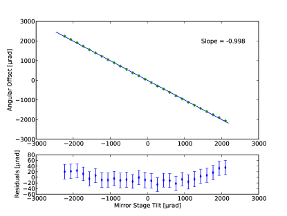
We performed tests with the autocollimator placed 8 m from a 5 cm circular mirror mounted on a tilt stage. We tilted the mirror over a range of rad and reconstructed the tilt from the reflected image of the LEDs obtained with the camera. The right panel on Fig. 1 summarizes the results from these tests, where we found an rms deviation from a linear fit of 16 rad. This is within the design goals.
4 Panel-to-panel alignment system
The positioning of each individual mirror panel is achieved by six linear actuators arranged in a Stewart platform (or hexapod) designed to situate the mirror panel with an accuracy better than the required 100 m. The relative positions of adjacent mirror panels are determined by a collection of mirror panel edge sensors (MPESs). The control of the SP and the MPESs is performed by a dedicated mirror panel controller board (MPCB) mounted onto an aluminum triangle that interfaces the entire setup with the optical support structure (OSS). We define a panel module (PM) as the full setup composed of a mirror panel, and its accompanying SP, MPES, MPCB and mounting triangle. Power and Ethernet are served to each of the 48 PMs in M1 and 24 PMs in M2 by two power and Ethernet distribution boxes (PEDBs), one per mirror. In turn, all the 72 PMs are controlled by a central computer in charge of the pSCT alignment.
4.1 Mirror Panel Edge Sensors
The MPESs are required to provide a positional resolution better than 10 m over an operational area of 1 cm2. The MPES measurements will be used to initially align the pSCT optical surfaces, providing input to compute the necessary adjustments of the SPs on individual mirror panels to compensate potential deformations of the OSS. These potential deformations may be caused by seasonal thermal expansion and/or changing loads in the pSCT structure as it moves. Although adjustments of the PMs are expected to be infrequent, MPESs will be performing measurements continuously to accumulate data for pointing calibration and PSF estimation.
Each MPES unit consists of two mechanically independent subunits: the sensor subunit and the light source subunit, as shown in Fig. 2. Each subunit consists of a weatherproof enclosure, containing the optical and electronic components. The light source subunits features a low-power diode laser whose beam is further collimated by a 300 m diameter pin hole located at the exit of the enclosure. The sensor subunit features a 0.3 Mpx webcam focused onto an opal glass that works as a diffusive target for the perpendicularly incident laser beam. Both subunits are connected and powered by the same USB line that is used to communicate with the webcam. A removable opaque UV-resistant thermoplastic elastomer conduit connects both subunits forming a single MPES unit, in such a way that the laser beam is light-tight and weatherproof. The whole MPES design has been proven to be weatherproof and has successfully passed total water submersion tests. It has been demonstrated through extensive laboratory tests that a ¡ 5 m positional resolution with a plate scale of 44m/px can be achieved with the current MPES design.
Each MPES presents a single optical axis defined by its laser beam. There is a single MPES configuration where the optical axis orientation forms an angle of 45∘ with the local mirror panel surface. Rotations of this basic configuration allows for triads of MPES with orthogonal optical axes. Adjacent mirror panels within the same ring segment will be interfaced with a triad of MPESs, consequently optimizing the measurement of the displacements in the allowed 6 dimensional space. Adjacent mirror panels belonging to different ring segments share a pair of MPES, thus allowing for inter-segment displacement measurements and for redundancy. The total number of MPESs per pSCT provides a 20% redundancy that should not cause malfunctioning of the alignment system in the event of malfunctioning of a small group of units. The installation of a limited number of MPESs interfacing the optical surfaces with the OSS is under consideration.
The production, alignment and calibration of circa 400 MPES units is currently ongoing. All units will be manufactured on time for the integration into the pSCT PMs.
4.2 Stewart Platforms
The actuators configuring the SP are capable of stepping in increments of 3 m within a range of 63 mm, while their position is measured by a magnetic encoder capable of detecting a single step. Both stepping motor and encoder are enclosed in a watertight aluminum cylinder.
The actuators are connected on both sides of the SP to six universal joints which are designed to minimize hysteresis using precisely machined aluminum and a crossed-axis configuration. The addition of the joints and actuators provide six degrees of freedom to move the mirror panels in any position within the range of the stepping motor (63 mm). The resulting SP occupies a space of approximately mm3. A stepping motor alone is capable to move a maximum weight of 65 kg at 500 steps/s. After assembly, the SP is able to move at least 50 kg in addition to its own weight ( 15 kg), more than enough to hold and align a single mirror panel ( 25 kg).
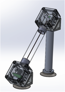
The 3 m steps of the actuators should provide a tip-tilt angular resolution of 1 arcsec for the mirror panels, but the actual alignment precision of the SP is mainly limited by the remaining hysteresis of the joints. This effect has been measured in the laboratory using prototype versions of the actuators and MPES, which were used to monitor the position of the SP (Fig. 3, central panel). The stability of this setup, which was measured using the MPES while the SP remains immobile, is better than 10 m (see Fig. 3, central panel, red dots). The effect of hysteresis was measured by moving the SP to a new position using a specific sequence of the actuators motion and moving back to the initial position through a different sequence. As shown in Fig. 3 (central panel, blue dots) the SP does not reach the exact same initial position, and the spread of these positions quantifies the amount of hysteresis remaining in the system. The measured standard deviations of these distributions are smaller than 26 m, depending on the load on the platform and its intermediate positions.
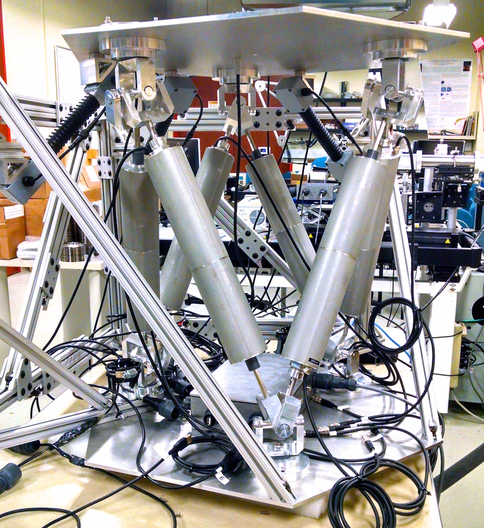
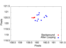
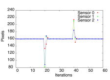
It is possible to mitigate some of the effects of hysteresis on the SP by re-adjusting several times its position around a desired value using a feedback loop with the MPES. Fig. 3 (right) shows some of the results obtained in laboratory where the actuators are constantly adjusted to reach a given position after inserting artificial perturbations. After perturbation, the SP was able to converge to the desired position within three iterations and to maintain it within 15 m. To achieve this result the response matrix of the actuators has been measured with the MPES using a linear approximation. This matrix was then inverted and applied several times to the actuators to reach a specific position on the MPES.
These results were obtained using a late prototype of the SP shown in Fig. 3 (left), which was used to produce the 72 platforms needed for the pSCT. All the parts of these platforms have been procured and are currently being assembled to be installed on the OSS around Fall 2015.
4.3 Mirror Panel Controller Board
Each PM will hold a controller box behind it. This MPCB is responsible for driving the actuators and the collection of the signal coming form the MPES, magnetic encoders and temperature sensors. The signal processing, communication and control will be handled by a Gumstix Overo® EarthSTORM on-board micro computer with Ethernet connectivity.
The production of 80 controller boxes is complete, and they are awaiting final testing and calibration, followed by installation of the production software.
4.4 Power and Ethernet Distribution Box
The PEDB system has two main functions: distribute Ethernet and 24 VDC power to all the telescope’s PMs. Additionally, the boxes supply power (12 VDC and 24 VDC) and Ethernet to several other systems including the global alignment system, and the gamma-ray camera LED flashing calibration system. Both M1 and M2 will be equipped with one PEDB each that will be installed on the OSS. Both PEDB units are housed in NEMA 3R outdoor-rated enclosures with ported forced-air cooling and temperature control. Ethernet connectivity is provided by two commercial-grade switches. Housekeeping and power supply control is provided by an Arduino Mega 2560 with Arduino© Ethernet shield. Additional analog input lines are provided by custom boards containing 12 bit ADCs which communicate via serial peripheral interface to the Arduino©. All power supply output voltages are monitored, as well as the currents to all Stewart platforms.
The two PEDBs for installation on the pSCT are currently undergoing final electrical testing and final installation of remaining connectors. Both boxes have been run for extensive periods in the laboratory and have not exhibited any abnormal behavior.
4.5 Integration and environmental tests
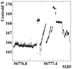

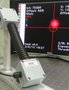
A panel module prototype (pPM) consisting of a full SP, a MPCB, an orthogonal triad of MPESs and a dummy aluminum-made mirror panel, along with a PEDB prototype, were assembled at the Fred Lawrence Whipple Observatory and installed on one of the VERITAS telescopes as a first hardware integration test. The setup, which ran continuously for 4.5 months starting in early 2014, demonstrated that the MPESs’ positioning measurements and the SP motion control were both within specifications, as well as positively verified the weatherproofness of all the participating hardware.
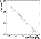
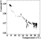
The MPESs measured relative true motion of the dummy aluminum plate correlated with changes in the gravitational loading of the assembly as the telescope slewed, as well as the relative true motion correlated with ambient temperature changes that is attributed to the thermal expansion of the pPM. Some examples of data recorded by an individual MPES can be found in Fig. 4 along with a picture of the pPM.
5 Alignment control software
The software controls of the panel-to-panel alignment system are implemented through the OPC-UA communication protocol. The implementation follows the server-client paradigm, with MPCBs on each panel acting as servers of MPES data; PEDBs on each mirror being servers of the system environment data; a central computer fulfilling the roles of client to the aforementioned servers and server of the processed data; and a database collector, a client to the central computer that handles archival data requests between the central computer and a database. The global alignment system control software will be similarly implemented, such that the entire pSCT alignment control software easily integrates with the higher-level Array Control system of the CTA.
6 Summary and outlook
We have presented an overview of the design and development status of the alignment system for a Schwarzschild-Couder medium-sized telescope candidate for the Cherenkov Telescope Array. The performance of all hardware components for the global and panel-to-panel alignment systems has been verified to work within specifications and the mass production of the same has been initiated and is compliant with the pSCT construction schedule.
For the final SC-MST design, the alignment system will be optimized for mass-scale production based on the knowledge acquired from the pSCT experience.
7 Acknowledgments
We gratefully acknowledge support from the agencies and organizations listed under Funding Agencies at this website: http://www.cta-observatory.org/. The development of the prototype SCT has been made possible by funding provided through the NSF-MRI program. We acknowledge the excellent work of the technical support staff at the Fred Lawrence Whipple Observatory.
References
- [1] B. Acharya et al., Introducing the CTA concept, Astroparticle Physics 43 (2013), no. 0 3 – 18.
- [2] V. V. Vassiliev, S. Fegan, and P. Brousseau, Wide field aplanatic two-mirror telescopes for ground-based -ray astronomy, Astroparticle Physics 28 (Sept., 2007) 10–27, [astro-ph/0612718].
- [3] J. Rousselle et al., Construction of a Schwarzschild-Couder telescope as a candidate for the Cherenkov Telescope Array: Implementation of the optical system, Proceedings of the 33rd International Cosmic Ray Conference (2013) [arXiv:1307.4072].
- [4] N. Otte et al., Development of a SiPM camera for a Schwarzschild-Couder Cherenkov telescope, 34th International Cosmic Ray Conference (2015).
- [5] K. Byrum et al., A medium sized Schwarzschild-Couder Cherenkov telescope design proposed for the Cherenkov Telescope Array, Proceedings of the 34th International Cosmic Ray Conference (2015).
- [6] T. Hassan et al., Layout design studies for medium-size telescopes within the Cherenkov Telescope Array, Proceedings of the 34th International Cosmic Ray Conference (2015) [arXiv:1508.06076].