Development of a Precise Polarization Modulator for UV Spectropolarimetry
Abstract
We developed a polarization modulation unit (PMU) to rotate a waveplate continuously in order to observe solar magnetic fields by spectropolarimetry. The non-uniformity of the PMU rotation may cause errors in the measurement of the degree of linear polarization (scale error) and its angle (crosstalk between Stokes- and -), although it does not cause an artificial linear polarization signal (spurious polarization). We rotated a waveplate with the PMU to obtain a polarization modulation curve and estimated the scale error and crosstalk caused by the rotation non-uniformity. The estimated scale error and crosstalk were 0.01 % for both. This PMU will be used as a waveplate motor for the Chromospheric Lyman-Alpha SpectroPolarimeter (CLASP) rocket experiment. We confirmed that the PMU has the sufficient performance and function for CLASP.
keywords:
Magnetic fields, Polarization1 Introduction
To understand the energy-release processes occurring in the Sun, it is important to measure the magnetic field, especially that in the upper layers of the solar atmosphere. The Zeeman effect is a powerful tool for revealing magnetic fields on the photosphere. However, it is difficult to apply the Zeeman effect for magnetic-field measurements in the upper chromosphere and above owing to weaker magnetic fields and larger thermal broadening in those layers. The use of high-precision spectropolarimetry to detect the Hanle effect enables us to overcome this difficulty and infer the vector magnetic field (Hanle, 1924; Trujillo Bueno et al., 2002; Trujillo Bueno, Štěpán, and Casini, 2011; Belluzzi and Trujillo Bueno, 2012; Ishikawa et al., 2014a).
Spectropolarimetry to observe solar magnetic fields are performed both with ground-based telescopes – such as the Tenerife Infrared Polarimeter (Mártinez Pillet et al., 1999), which is attached to the German Vacuum Tower Telescope in Tenerife, and the Advanced Stokes Polarimeter (Elmore et al., 1992) – and with space telescopes such as the Solar Optical Telescope (Tsuneta et al., 2008; Lites et al., 2013) onboard the Hinode spacecraft (Kosugi et al., 2007). The Stokes parameters can be obtained by measuring the polarization modulations. Although there are several ways to modulate the intensity, one of the widely used methods combines a continuously rotating waveplate and a polarization analyzer (Lites, 1987). The continuously rotating waveplate offers advantages such as a simple control system and no dead time caused by the waveplate rotation. In this case, the non-uniformity of the continuous waveplate rotation causes errors in the polarization measurement.
Errors in a polarization measurement can be classified into spurious polarization, scale error, and crosstalk among the Stokes parameters , , and (Ichimoto et al., 2008). The rotation non-uniformity of the waveplate rotator does not cause spurious polarization but may cause scale error or crosstalk. The scale error is the error in magnitude of each Stokes parameter: , , and . It can be evaluated as , where is the degree of polarization of the incident light, and is its measured value.
The SOLAR-C working group of the Institute of Space and Astronautical Science (ISAS), together with the Mitsubishi Precision Company, has been developing a motor to rotate a waveplate continuously for the Solar UV-Vis-IR Telescope (SUVIT: Katsukawa et al. 2013) onboard the next solar spacecraft SOLAR-C (Shimizu et al., 2014). We plan to use a development model of the motor for a rocket experiment named the Chromospheric Lyman-Alpha SpectroPolarimeter (CLASP) to observe the linear polarization profile of the Lyman- line (vacuum ultraviolet, 121.6 nm) from the Sun in order to perform magnetic-field measurements in the upper chromosphere and transition region (Kano et al., 2012; Kobayashi et al., 2012). In the CLASP instrument, the motor will continuously rotate a half-waveplate (Ishikawa et al., 2013), and is required to have rotation uniformity for the linear polarization to be measured precisely.
The total tolerance of the scale error is 10 % for CLASP (Ishikawa et al., 2014b). There are several sources of the scale error, and some of them contribute significantly (i.e. the camera readout nonlinearity and scattered light contribute a few percent). Therefore, it is required that the scale error due to the waveplate rotator is on the order of 1 % or lower.
The tolerance of the error in the polarization-angle measurement is 2∘ for CLASP (Ishikawa et al., 2014b). For the Stokes parameters with and , the polarization-angle deviation of 2∘ causes deviations of the Stokes parameters and as and , respectively. Therefore if and , the crosstalk can be written as , and its tolerance is 7 %. Because the circular polarization is expected to be negligible in the case of the solar Lyman- observation (Ishikawa et al., 2014b), we consider only the crosstalk between and here.
We developed a polarization modulation unit (PMU), i.e. a system to rotate the half-waveplate (Ishikawa et al., 2013) continuously, comprising a rotating motor (PMU-ROT) and its driver electronics (PMU-DRV). The PMU-ROT used for CLASP is the second-generation model developed for SOLAR-C. Its control circuit in the PMU-DRV is newly developed for the precise rotation. The PMU is designed to be robust for not only a rocket experiment but also space applications. The CLASP experiment is an opportunity to demonstrate that the motor configuration and control technique can be used in space for SOLAR-C. The long-term performance is an important factor for spacecraft applications, and it is tested separately (Shimizu et al., 2014). In this article, we describe the specifications and control technique for the PMU and report the experimental results of the effect on the polarization measurement.
2 Design of PMU
The PMU-ROT is a three-phase brushless direct-current motor and the PMU-DRV is designed to rotate the waveplate with a period of 4.8 seconds for CLASP (Kano et al., 2012). The PMU maintains the rotation rate of 4.8 seconds per rotation by measuring the rotation angle using an optical encoder and the time by counting clock-signal pulses from the central processor unit (CPU). The feedback gain and other parameters are optimized according to the rotation speed and moment of inertia of the flight configuration. Low-pass filters are used in the feedback loop to reduce the influence of momentary disturbances.
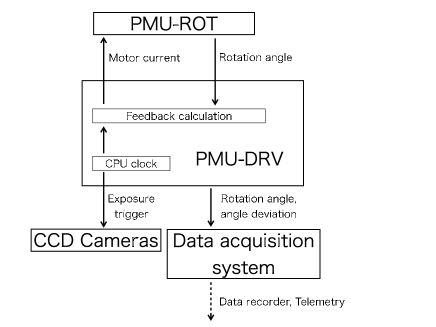
The timing of the exposure of the images should be synchronized with the rotation angle of the waveplate. If the exposure signal is generated by the angle measured using the encoder, the exposure duration may fluctuate because of the non-uniform rotation. Therefore, the PMU regularly calculates the target angle to maintain the uniform rotation based on the CPU clock in the PMU-DRV, and also generates an exposure synchronization signal regularly every 0.3 seconds by the same CPU clock, independently from the measured angle. Frame-transfer type charge coupled device (CCD) cameras receive the exposure synchronization signal. They then finish the ongoing exposures, transfer the frames, and start the next exposures. The PMU also outputs the measured rotation angle and angle deviation from the target angle to check the non-uniformity in the rotation. Those values are downlinked to the ground station by the telemetry during the flight. The signal diagram is shown in Figure \ireffig:signaldiagram.
Materials with a low outgassing rate are selected for the PMU (Imada et al., 2011). This is especially important for vacuum-ultraviolet observations. For CLASP, we baked out the PMU-ROT and confirmed using a thermoelectric quartz-crystal microbalance that it exhibited no significant continued outgassing.
3 Measurements of Rotation Uniformity and Influence on Polarization Measurement
We performed polarization modulation measurements to estimate the scale error and crosstalk for the flight instruments PMU-ROT and PMU-DRV. The uniform rotation of the PMU can be disturbed by momentary torque disturbances in the lubricant, the machining accuracy of the optical encoder, and the PMU-ROT structure itself. The PMU-ROT has 11 magnets (Shimizu et al., 2014) which may cause periodic deviation of the rotation. Therefore, it is important to evaluate the scale error and crosstalk due to the PMU to confirm its performance.
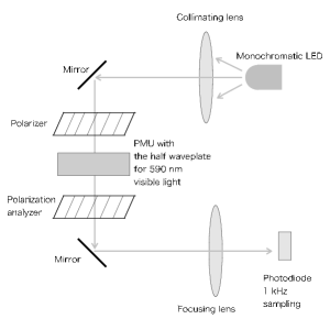
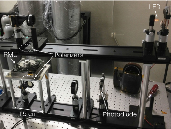
The optical system of the experiment is shown in Figure \ireffig:rottest. A light-emitting diode (LED, EK Japan LK-5YE) emitting monochromatic light at a wavelength of 590 nm, with a wavelength width less than 10 nm, is used as a light source. The variations of the luminosity are measured to be less than 0.1 % during the time scale of 1 minute. The LED light is collimated by a collimating lens and linearly polarized by a stack of two polarizers, and it is used as the incident beam for the rotating waveplate. The collimated linearly polarized light illuminates the rotating half-waveplate mounted on the PMU, which changes the direction of the linear polarization continuously. The waveplate used in this experiment is not for the Lyman- line; rather, it is a commercial waveplate for visible light with a wavelength of 590 nm (Sigma Corporation WPQ-5900-2M). After passing the waveplate, the light passes through a stack of two polarization analyzers – which are identical to the polarizers located upstream of the waveplate – and is focused on a photodiode. The polarizers before the waveplate and the polarization analyzers after the waveplate are aligned in the same direction, vertical to the incident and reflected lights. The intensity modulation is measured by a silicon photodiode (Hamamatsu Photonics S1337) at a sampling frequency of 1 kHz. The wavelength width of the light source and the wavelength dependence of the retardation of the waveplate cause a constant offset in the intensity modulation. The monochromatic LED light source is selected to minimize this offset. The experimental setup is covered by a blackout curtain, and the influence of stray light can be ignored. Although the observation duration for the sounding rocket is limited to five minutes, to evaluate the scale error and crosstalk, we measure the polarization modulation for one hour, corresponding to 737 rotations.
The intensity modulation measured using the LED is described by the following equation:
| (1) |
where is the constant amplitude, is the rotation angle, is time, and is the constant offset caused by the wavelength width of the light source and wavelength dependence of the retardation of the waveplate. The ideal intensity intensity with uniform waveplate rotation at the rate is given as
| (2) |
where is the initial angle and is the angular velocity. In our experiment, we confirmed that the background intensity is sufficiently smaller than , and its time dependence is negligible. Therefore, the residual caused by the rotation non-uniformity can be written as
| (3) |
Assuming that the angular deviation is sufficiently small, the relation between and can be described as
| (4) |
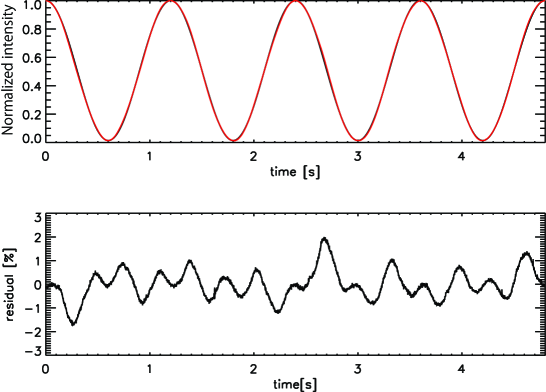
Figure \ireffig:modulation shows an example of the measured intensity modulation during a single rotation, according to the data measured continuously for one hour. As shown in the upper panel, the measured modulation and the fitted sinusoidal curve (black and red lines respectively) almost overlap each other. The fitting is performed for each single rotation using the function given by Equation (\irefeq:ideal), where the free parameters are , , and . We use the fixed value of from the specification of the PMU. As shown in the lower panel, the residual between the measured and fitted curves is less than 2 % during the rotation, which corresponds roughly to an angular deviation of 1 ∘, according to Equation (\irefeq:angledev).
In the residual, we observe 15 peaks during one rotation and seven groups of them, each comprising two or three continuous peaks. This pattern is observed at any time in the one-hour data, and is well explained by the structure of the PMU-ROT.
Because the PMU-ROT has 11 magnets, as previously mentioned, it is expected that the angular deviation has a periodicity of 11 times per rotation. Accordingly, , where is the initial phase of the magnets. Therefore, the product of and yields beats with periodicities of and .
To simulate the CCD camera operation during the flight, we integrated the intensity every 0.3 second (16 exposures per rotation) and then calculated the Stokes and using the demodulation formula for the actual flight data (see Equation (1) of Ishikawa et al. 2014b). Similarly, we also calculated Stokes- and - for the ideal rotation – and respectively – using the fitted modulation curve. Because we extracted the data for each rotation from the local maximum in the intensity modulation, the data indicate that and . Neither nor is exactly zero, as the sampling timings and peaks of the intensity modulation are not synchronized. In this situation, we can evaluate the scale error and crosstalk in the linear polarization as and , respectively. The scale error and crosstalk for every single rotation in the one-hour operation are plotted in Figure \ireffig:scaleerror. They were always less than 0.03 %.
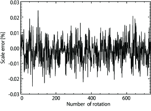
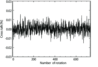
The average and standard deviation of the scale error in the data for the 737 rotations in the one-hour measurement are presented in Table \ireftable.
| Component | Average [%] | Scale error [%] |
|---|---|---|
| Scale error | 0.002 | 0.008 |
| Cross talk | 0.001 | 0.005 |
The average corresponds to the non-uniformity synchronized to the rotation period (as shown in the bottom panel of Figure \ireffig:modulation), and the standard deviation mainly corresponds to the random fluctuation in the rotation, such as variations in the condition of the lubricant. The 1 error of the scale error is less than , and the 3 error is less than , which is small compared with the other error origins (Ishikawa et al., 2014b). Because the temporal variation of the scale error appears almost random around its average, the scale error can be reduced by integrating more rotations to calculate the Stokes-.
The average and standard deviation of the crosstalk in the same data set are also shown in Table \ireftable. As before, the 1 error of the scale error is less than , and the 3 error is less than , which is also small. The crosstalk can also be reduced by integrating more rotations.
4 Conclusions
We developed a polarization modulation unit to rotate a waveplate continuously for precise spectropolarimetry. In measuring the linear polarization, we evaluated the scale error and crosstalk, finding that both are % or less (1 errors). This result shows that the scale error caused by the rotation non-uniformity has a far smaller influence than the other effects (Ishikawa et al., 2014b). Both the scale error and the crosstalk satisfy the requirements for CLASP.
Acknowledgements
We would like to thank H. Hara at the National Astronomical Obsevatory of Japan, S. Obara and K. Watanabe at JAXA, and S. Imada at Nagoya University for the development of the PMU-ROT. We also thank S. Hirata, M. Matsumoto and A. Urayama at the Mitsubishi Precision Co.,Ltd for the development of both of the PMU-ROT and PMU-DRV, and the Techno-Craft Co. for the development of the PMU-DRV. The PMU-ROT is developed with supports by the JAXA strategic research and development grant to the JAXA SOLAR-C working group. The CLASP sounding rocket experiment is founded by NASA, CNES, JAXA, and the Japan Society for the Promotion of Science (JSPS) through a Grant-in-Aid for Scientific Research (S) (Grant Number 25220703, PI: S. Tsuneta). The development of CLASP in Japan was also supported by the basic research program of the Institute of Space and Astronomical Science (ISAS), internal research funding of the National Astronomical Observatory of Japan (NAOJ), and JSPS KAKENHI Grant Numbers 24340040, 23340052, and 24740134. The authors also acknowledge N. Okada at the Advanced Technology Center of NAOJ for his support in preparation of the experimental jigs.
Disclosure of Potential Conflicts of Interest
The authors declare that they have no conflicts of interest.
References
- Belluzzi and Trujillo Bueno (2012) Belluzzi, L., Trujillo Bueno, J.: 2012, The Polarization of the Solar Mg II h and k Lines. ApJ 750, L11. DOI. ADS.
- Elmore et al. (1992) Elmore, D.F., Lites, B.W., Tomczyk, S., Skumanich, A.P., Dunn, R.B., Schuenke, J.A., Streander, K.V., Leach, T.W., Chambellan, C.W., Hull, H.K.: 1992, The Advanced Stokes Polarimeter - A new instrument for solar magnetic field research. In: Goldstein, D.H., Chipman, R.A. (eds.) Polarization Analysis and Measurement, Soc. Photo-Opt. Instrument. Eng. (SPIE), CS-1746, 22. ADS.
- Hanle (1924) Hanle, W.: 1924, Über magnetische Beeinflussung der Polarisation der Resonanzfluoreszenz. Zeit. fur Phys. 30, 93. DOI. ADS.
- Ichimoto et al. (2008) Ichimoto, K., Lites, B., Elmore, D., Suematsu, Y., Tsuneta, S., Katsukawa, Y., Shimizu, T., Shine, R., Tarbell, T., Title, A., Kiyohara, J., Shinoda, K., Card, G., Lecinski, A., Streander, K., Nakagiri, M., Miyashita, M., Noguchi, M., Hoffmann, C., Cruz, T.: 2008, Polarization Calibration of the Solar Optical Telescope onboard Hinode. Sol. Phys. 249, 233. DOI. ADS.
- Imada et al. (2011) Imada, S., Shimizu, T., Watanabe, K., Bando, T., Tsuneta, S., Hara, H.: 2011, Contamination Evaluation of High Duty Cycle, Space-Qualified Wheel Mechanisms for Onboard Telescopes. JAXA reseach and development report JAXA-RR-10-012, JAXA, Tokyo, 1.
- Ishikawa et al. (2013) Ishikawa, R., Kano, R., Bando, T., Suematsu, Y., Ishikawa, S.-n., Kubo, M., Narukage, N., Hara, H., Tsuneta, S., Watanabe, H., Ichimoto, K., Aoki, K., Miyagawa, K.: 2013, Birefringence of magnesium fluoride in the vacuum ultraviolet and application to a half-waveplate. Appl. Opt. 52, 8205. DOI. ADS.
- Ishikawa et al. (2014a) Ishikawa, R., Asensio Ramos, A., Belluzzi, L., Manso Sainz, R., Štěpán, J., Trujillo Bueno, J., Goto, M., Tsuneta, S.: 2014a, On the Inversion of the Scattering Polarization and the Hanle Effect Signals in the Hydrogen Ly Line. ApJ 787, 159. DOI. ADS.
- Ishikawa et al. (2014b) Ishikawa, R., Narukage, N., Kubo, M., Ishikawa, S., Kano, R., Tsuneta, S.: 2014b, Strategy for Realizing High-Precision VUV Spectro-Polarimeter. Sol. Phys. 289, 4727. DOI. ADS.
- Kano et al. (2012) Kano, R., Bando, T., Narukage, N., Ishikawa, R., Tsuneta, S., Katsukawa, Y., Kubo, M., Ishikawa, S.-n., Hara, H., Shimizu, T., Suematsu, Y., Ichimoto, K., Sakao, T., Goto, M., Kato, Y., Imada, S., Kobayashi, K., Holloway, T., Winebarger, A., Cirtain, J., De Pontieu, B., Casini, R., Trujillo Bueno, J., Štepán, J., Manso Sainz, R., Belluzzi, L., Asensio Ramos, A., Auchère, F., Carlsson, M.: 2012, Chromospheric Lyman-alpha spectro-polarimeter (CLASP). Soc. Photo-Opt. Instrument. Eng. (SPIE), CS-8443, 4. DOI. ADS.
- Katsukawa et al. (2013) Katsukawa, Y., Ichimoto, K., Suematsu, Y., Hara, H., Kano, R., Shimizu, T., Matsuzaki, K.: 2013, Design progress of the solar UV-Vis-IR telescope (SUVIT) aboard SOLAR-C. Soc. Photo-Opt. Instrument. Eng. (SPIE), CS-8862, 0. DOI. ADS.
- Kobayashi et al. (2012) Kobayashi, K., Kano, R., Trujillo-Bueno, J., Asensio Ramos, A., Bando, T., Belluzzi, L., Carlsson, M., De Pontieu, R.C.B., Hara, H., Ichimoto, K., Ishikawa, R., Katsukawa, Y., Kubo, M., Manso Sainz, R., Narukage, N., Sakao, T., Stepan, J., Suematsu, Y., Tsuneta, S., Watanabe, H., Winebarger, A.: 2012, The Chromospheric Lyman-Alpha SpectroPolarimeter: CLASP. In: Golub, L., De Moortel, I., Shimizu, T. (eds.) Fifth Hinode Science Meeting, CS-456, Astron. Soc. Pacific, San Francisco, 233. ADS.
- Kosugi et al. (2007) Kosugi, T., Matsuzaki, K., Sakao, T., Shimizu, T., Sone, Y., Tachikawa, S., Hashimoto, T., Minesugi, K., Ohnishi, A., Yamada, T., Tsuneta, S., Hara, H., Ichimoto, K., Suematsu, Y., Shimojo, M., Watanabe, T., Shimada, S., Davis, J.M., Hill, L.D., Owens, J.K., Title, A.M., Culhane, J.L., Harra, L.K., Doschek, G.A., Golub, L.: 2007, The Hinode (Solar-B) Mission: An Overview. Sol. Phys. 243, 3. DOI. ADS.
- Lites (1987) Lites, B.W.: 1987, Rotating waveplates as polarization modulators for Stokes polarimetry of the sun - Evaluation of seeing-induced crosstalk errors. Appl. Opt. 26, 3838. DOI. ADS.
- Lites et al. (2013) Lites, B.W., Akin, D.L., Card, G., Cruz, T., Duncan, D.W., Edwards, C.G., Elmore, D.F., Hoffmann, C., Katsukawa, Y., Katz, N., Kubo, M., Ichimoto, K., Shimizu, T., Shine, R.A., Streander, K.V., Suematsu, A., Tarbell, T.D., Title, A.M., Tsuneta, S.: 2013, The Hinode Spectro-Polarimeter. Sol. Phys. 283, 579. DOI. ADS.
- Mártinez Pillet et al. (1999) Mártinez Pillet, V., Collados, M., Sánchez Almeida, J., González, V., Cruz-Lopez, A., Manescau, A., Joven, E., Paez, E., Diaz, J., Feeney, O., Sánchez, V., Scharmer, G., Soltau, D.: 1999, LPSP TIP: Full Stokes Polarimeters for the Canary Islands Observatories. In: Rimmele, T.R., Balasubramaniam, K.S., Radick, R.R. (eds.) High Resolution Solar Physics: Theory, Observations, and Techniques, CS-183, Astron. Soc. Pacific, San Francisco, 264. ADS.
- Shimizu et al. (2014) Shimizu, T., Watanabe, K., Nakayama, S., Tajima, T., Obara, S., Imada, S., Nishizuka, N., Ishikawa, S.-n., Hara, H.: 2014, New developments in rotating and linear motion mechanisms used in contamination sensitive space telescopes. Soc. Photo-Opt. Instrument. Eng. (SPIE), CS-9151, 38. DOI. ADS.
- Trujillo Bueno, Štěpán, and Casini (2011) Trujillo Bueno, J., Štěpán, J., Casini, R.: 2011, The Hanle Effect of the Hydrogen Ly Line for Probing the Magnetism of the Solar Transition Region. ApJ 738, L11. DOI. ADS.
- Trujillo Bueno et al. (2002) Trujillo Bueno, J., Landi Degl’Innocenti, E., Collados, M., Merenda, L., Manso Sainz, R.: 2002, Selective absorption processes as the origin of puzzling spectral line polarization from the Sun. Nature 415, 403. ADS.
- Tsuneta et al. (2008) Tsuneta, S., Ichimoto, K., Katsukawa, Y., Nagata, S., Otsubo, M., Shimizu, T., Suematsu, Y., Nakagiri, M., Noguchi, M., Tarbell, T., Title, A., Shine, R., Rosenberg, W., Hoffmann, C., Jurcevich, B., Kushner, G., Levay, M., Lites, B., Elmore, D., Matsushita, T., Kawaguchi, N., Saito, H., Mikami, I., Hill, L.D., Owens, J.K.: 2008, The Solar Optical Telescope for the Hinode Mission: An Overview. Sol. Phys. 249, 167. DOI. ADS.