Metallic nanolines ruled by grain boundaries in graphene: an ab initio study
Abstract
We have performed an ab initio investigation of the energetic stability, and the electronic properties of transition metals (TMs = Mn, Fe, Co, and Ru) adsorbed on graphene upon the presence of grain boundaries (GBs). Our results reveal an energetic preference for the TMs lying along the GB sites (TM/GB). Such an energetic preference has been strengthened by increasing the concentration of the TM adatoms; giving rise to TM nanolines on graphene ruled by GBs. Further diffusion barrier calculations for Fe adatoms support the formation of those TM nanolines. We find that the energy barriers parallel to the GBs are sligthly lower in comparision with those obtained for the defect free graphene; whereas, perpendicularly to the GBs the Fe adatoms face higher energy barriers. Fe and Co (Mn) nanolines are ferromagnetic (ferrimagnetic), in contrast the magnetic state of Ru nanolines is sensitive to the Ru/GB adsorption geometry. The electronic properties of those TM nanolines were characterized through extensive electronic band structure calculations. The formation of metallic nanolines is mediated by a strong hybridization between the TM and the graphene () orbitals along the GB sites. Due to the net magnetization of the TM nanolines, our band structure results indicate an anisotropic (spin-polarized) electronic current for some TM/GB systems.
pacs:
Valid PACS appear hereI Introduction
Topological defects in two dimensional systems has been the subject of several studies addressing not only their intrinsic properties, but also the use of those structural defects to perform nanoengineering on 2D platforms. Currently, graphene has been the most studied 2D platform; where we may have localized topological defects like Stone-Wales Choi et al. (2000); Meyer et al. (2008) and self-interstitials Lusk and Carr (2008); Lehtinen et al. (2015), or extended defects like grain boundaries Simonis et al. (2002); Yazyev and Louie (2010a); Huang et al. (2011).
Grain boundaries (GBs) may change the electronic transport properties in graphene Yazyev and Louie (2010b); Botello-Mendéz et al. (2011). Very recently, extended defects have been synthesized in a controlled way, giving rise to (i) metallic channels embedded in graphene Lahiri et al. (2010). Meanwhile, (ii) ferromagnetic properties have been predicted along the GB sites in graphene, upon external tensile strain Kou et al. (2011) or n-type doping Alexandre et al. (2012). Further theoretical studies indicate that (iii) through a suitable incorporation of nitrogen atoms along the GB sites, we may have an electronic confinement effects, giving rise to semiconductor channels in graphene Brito et al. (2014). Those properties [(i)–(iii)] depend on the atomic geometry along the GBs.
The presence of reconstructed defects enhances the chemical reactivity of the GB sites Cretu et al. (2010). Indeed, GBs in graphene have been identified by deposition of foreign elements, like silver Kebailia et al. (2009) or gold Yu et al. (2014a). Such an enhanced reactivity can be used to mediate (self) assembly processes on graphene, giving rise to nanoline (NL) strutures ruled by GBs. Those NLs may provide a set of new/useful electronic and chemical properties. In a recent experimental work Kim et al. (2014), the authors verified that the performance of hydrogen gas sensors was improved, upon the formation of linear structure of Pt adatoms along the GB sites. Further theoretical studies indicate that NLs of Fe and Mn adatoms lying along the GBs, composed by a pair of pentagons and an octagon Lahiri et al. (2010), give rise to half-metallic nature for the electronic transport along the Fe or Mn decorated GB sites Zhu et al. (2014); Obodo et al. (2015). Indeed, somewhat similar spin-polarized current, dictated by the presence of foreign atoms, has been predicted along the edge sites of graphene nanoribbons Martins et al. (2007); Rigo et al. (2009).
In this work we have performed an ab initio study, based on the density functional theory (DFT), of the energetic stability and the electronic properties of transition metals (TMs = Mn, Fe, Co, and Ru) adsorbed on graphene upon the presence of grain boundaries. Here we have considered a number of plausible TM–GB configurations for two different GB geometries. We find an energetic preference for the TMs lying along the GB sites (TM/GB), giving rise to TM nanolines (TM-NLs) ruled by GBs. Due to the metal–metal (chemical) interactions, the energetic stability of the TM/GB structures has been strengthened by increasing the concentration of TM adatoms along the GB sites. Those results provide further support to the recent experimental findings of linear structures of TMs on graphene, patterned by GBs Kebailia et al. (2009); Yu et al. (2014a); Kim et al. (2014). In addition, due to the net magnetic moment of the TM adatoms, we find that the Fe- and Co-NLs are ferromagnetic, while Mn-NLs are ferrimagnetic. In contrast, the magnetic state (ferromagnetic/nonmagnetic) of Ru-NLs is sensitive to the (local) adsorption geometry. Our electronic band structure calculations reveal that the (most of) TM/GB systems are metallic, and indicate a spin-anisotropy for the electronic current along the TM-NLs.
II Method
The calculations were performed based on the DFT approach, as implemented in the VASP code Kresse and Furthmller (1996). The exchange correlation term was described by using the spin-polarized GGA approach, in the form proposed by Perdew, Burke and Ernzerhof Perdew et al. (1996). The Kohn-Sham orbitals are expanded in a plane wave basis set with an energy cutoff of 400 eV. The 2D Brillouin Zone (BZ) is sampled according to the Monkhorst-Pack method Monkhorst and Pack (1976) (MP), using a 881 mesh for GB(5-8) and 661 mesh for GB(5-7). We made additional convergence tests with respect to the energy cutoff (up 450 eV) and BZ sampling (MP mesh of up to 20201). The electron-ion interactions are taken into account using the Projector Augmented Wave (PAW) method Kresse and Joubert (1999). All geometries have been relaxed until atomic forces were lower than 0.025 eV/Å. The molecule/graphene system is simulated using the slab method, by considering a vacuum region in the direction perpendicular to graphene sheet of at least 8 Å.
III Results
III.1 TM/Graphene and Pristine GBs
Initially we examine the energetic stability and the electronic properties of the TMs (TMs = Mn, Fe, Co, and Ru) adsorbed on the pristine graphene layer. The adsorption energy can be written as,
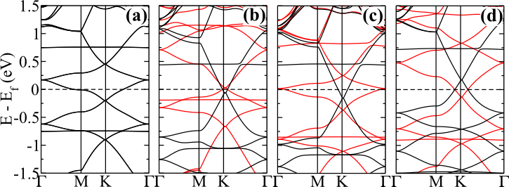
where and are the total energies of the separated components, graphene sheet and TM atom, and is the total energy of the final system, namely graphene sheet adsorbed by TM, TM/graphene. In Table I we present our results of , net magnetic moment (m), and the nearest neighbor (NN) TM–C equilibrium distances for the TMs adsorbed on the (energetically more stable) hollow sites of graphene. Here, we find a good agreement with the previous theoretical studies, viz.: = 0.17 eV/Mn-atom Sevinçli et al. (2008), = 1.02, 0.85, and 0.65 eV/Fe-atom Sevinçli et al. (2008); Chan et al. (2008); Wang et al. (2009), = 1.27 eV/Co-atom Sevinçli et al. (2008), and = 2.64 eV/Ru-atom Mera Acosta et al. (2014). The electronic band structures of TM/graphene are presented in Fig. 1. The linear energy dispersion at the K and K’ points have been preserved, however, for Fe/, Co/, and Ru/graphene systems the Dirac cones exhibit a spin-split due to the exchange-field induced by the adatoms.
| TM | TM–C | m | |
|---|---|---|---|
| Mn | 0.19 | 2.08 | 0.00 |
| Fe | 0.73 | 2.11 | 2.01 |
| Co | 1.14 | 2.11 | 1.16 |
| Ru | 2.41 | 2.25 | 1.46 |
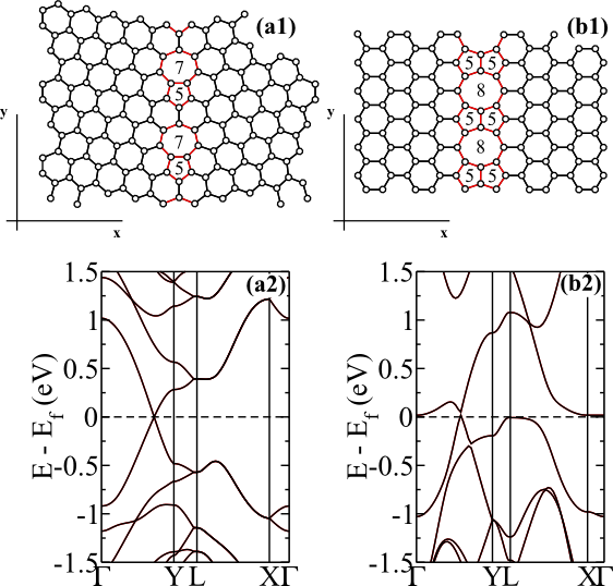
In Fig. 2 we present the structural models of GBs in graphene, and their electronic band structures. In GB(5-7) we have a defect line composed by carbon pentagons and heptagons embedded in the graphene sheet [Fig. 2(a1)], whereas GB(5-8) is composed by two pentagons and an octagon along the graphene zigzag direction [Fig. 2(b1)]. The electronic band structures are characterized by a linear energy dispersion, near the Dirac Point (DP), for wave vectors parallel to the defect lines, Figs. 2(a2) and 2(b2). Scanning tunelling microscopy (STM) experiments show the formation of bright lines along the GBs in graphene Simonis et al. (2002); Lahiri et al. (2010); Huang et al. (2011) . Such STM picture has been supported by recent first-principles simulations Yazyev and Louie (2010a), and indicates that the electronic states near the Fermi level () are mostly localized along the GBs. The increase of the electronic density of states near suggests a more reactive character of the GB sites in comparison with the pristine region of the graphene sheet Brito et al. (2011). Indeed, our results reveal that there is an energetic preference for TMs adsorbed along the GB sites of GB(5-7) and GB(5-8).
| TM/GB(5-8) | m | |||
|---|---|---|---|---|
| P | O | P | O | |
| Mn | 1.31 | 1.16 | 4.30 | 4.27 |
| Fe | 1.62 | 1.61 | 2.76 | 3.12 |
| Co | 2.00 | 1.64 | 0.93 | 1.89 |
| Ru | 3.63 | 2.81 | 0.00 | 1.70 |
| TM/GB(5-7) | m | |||
| P | H | P | H | |
| Mn | 0.87 | 0.79 | 4.48 | 4.21 |
| Fe | 1.06 | 1.36 | 2.54 | 2.13 |
| Co | 1.52 | 1.53 | 1.03 | 1.05 |
| Ru | 3.05 | 2.78 | 0.00 | 1.71 |
III.2 One TM per GB unit cell
We have considered a number of plausible configurations of TMs adsorbed along the GB sites (TM/GB); where we confirm the energetic preference of TM/GB, when compared with the TMs adsorbed on the pristine graphene. For instance, we find that the Fe adatoms lying on the pentagonal (P) rings of GB(5-8), Fe[P]/GB(5-8), are more strongly attached to the graphene sheet by around 0.9 eV/atom, eV/atom. The same increase on the adsorption energy was verified for Co[P]/GB(5-8). For Mn[P]/ and Ru[P]/GB(5-8) the adsorption energy increases by about 1.2 eV/atom. TMs adsorbed on the octagonal (TM[O]) ring is the second most stable configuration for Mn, Co and Ru, while Fe[P]/ and Fe[O]/GB(5-8) present almost the same adsorption energies. Our results of adsorption energies and the net magnetic moments are summarized in Table II. The energetic preference for Fe[P]/, and Co[P]/GB(5-8) are in agreement with the previous theoretical studies Zhu et al. (2014); Yu et al. (2014b); Obodo et al. (2015), however, the same does not occur for the Mn adatom. We find an energetic preference for the pentagonal sites, Mn[P]/GB(5-8) Yu et al. (2014b), instead of Mn[O]/GB(5-8) Zhu et al. (2014); Obodo et al. (2015). In order to verify the accuracy of our results, we have performed additional calculations including up Mn-3s as valence orbitals for the Mn pseudopotential, (i) within the PAW approach Blchl (1994); Kresse and Joubert (1999), and (ii) using ultrasoft Vanderbilt pseudopotentials Vanderbilt (1990). In (i) we have used the VASP code, as described in Section II (increasing the energy cutoff to 450 eV), and in (ii) we have used the Quantum-ESPRESSO code Giannozzi et al. (2009); MnG . In both cases [(i) and (ii)], the energetic preference for the P sites was confirmed, being the Mn[P]/GB(5-8) more stable than Mn[O]/GB(5-8) by 0.16 and 0.15 eV, respectively.
The energetic preference for the GB sites has been also verified in TM/GB(5-7); however, compared with the TM/GB(5-8) systems, the adsorption energies are lower by 0.3–0.5 eV/atom for the most stable configurations. The adsorption energy results are also summarized in Table II; where we find that (i) the energetic preference for the pentagonal rings for Mn and Ru adatoms has been maintained, while (ii) Fe adatoms are more stable by 0.3 eV on the heptagonal (H) ring, and (iii) for Co adatoms, the P and H rings present almost the same adsorption energies.
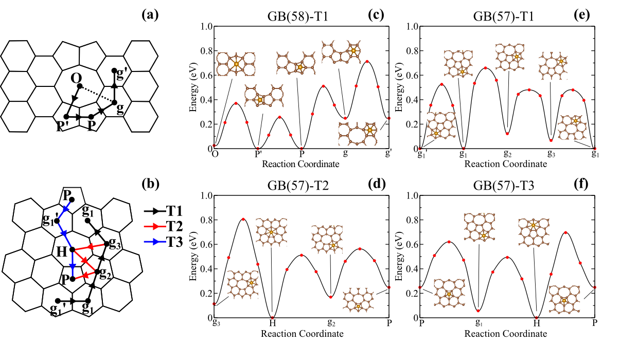
In particular, for the Fe/GB systems, we examined the Fe diffusion on the GB(5-8) and GB(5-7) defect lines. The energy barriers were estimated by using the CI-NEB approach Henkelman et al. (2000). For the Fe/GB(5-8) system, we have considered the diffusion path T1, depicted in Fig. 3(a). We find that (i) the energy barrier ( eV) for Fe diffusion along the GB sites passing through the C–C bridge site, Fe[O]Fe[P’]Fe[O] or Fe[O]Fe[P’]Fe[P]Fe[O] in Fig. 3(c), is lower than the one passing through hexagonal sites, Fe[g’] ( eV); and (ii) the Fe adatom will face energy barrier of about 0.5 eV to move out from the GB(5-8) defect line, Fe[P]Fe[g]. In Fe/GB(5-7), (iii) the Fe energy barriers along the hexagonal sites neighboring the GB, diffusion path T1 in Figs. 3(b) and 3(e), are slightly larger ( between 0.5–0.6 eV) compared with the one in GB(5-8); and (iv) the energy barriers from the hexagonal site g2 to the H and P sites along T2 [Fig. 3(d)], and from the hexagonal site g’1 to the H site along T3 [Fig. 3(f)] are slightly lower when compared with the energy barrier along T1, Fig. 3(e). In contrast, (v) for the diffusion path Fe[H]Fe[P] (T3) we find of 0.70 eV, and thus suggesting that the Fe diffusion along the GB(5-7) will take place passing through the neighboring hexagonal (g sites), for instance Fe[H]Fe[g2]Fe[P] along T2. Those results suggest that the there is an energetic preference for the Fe diffusion along the GB sites of GB(5-8) [(i) and (ii)], and GB(5-7) [(iv) and (v)]. Similar picture is expected for the other TM/GB systems.
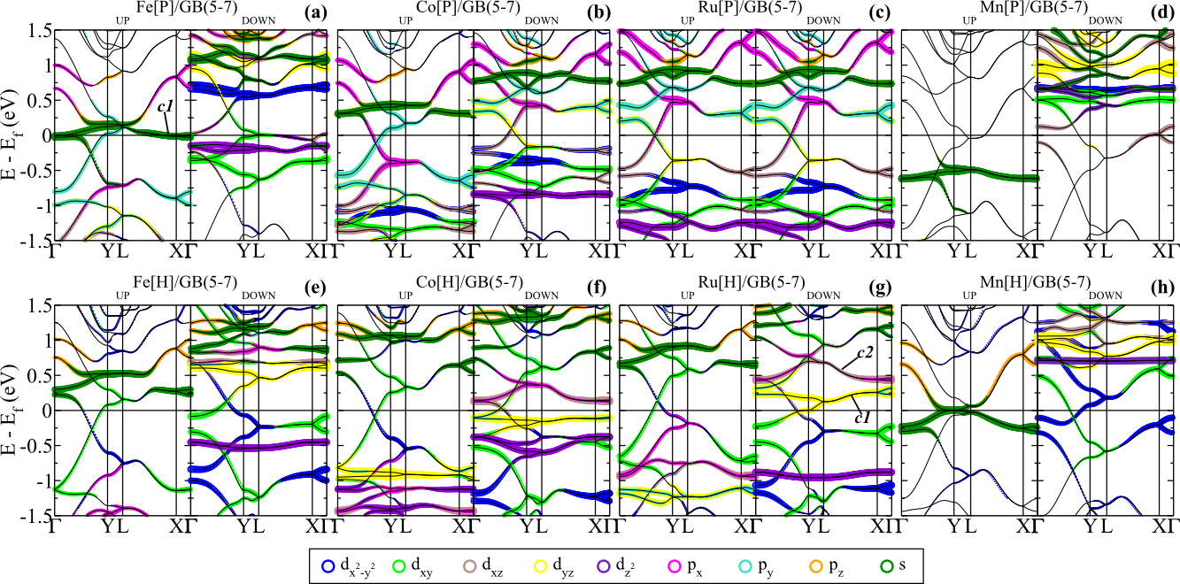
In GB(5-8) and GB(5-7), the electronic states near the Fermi level are mostly localized along the GB sites Simonis et al. (2002); Lahiri et al. (2010); Yazyev and Louie (2010a); Huang et al. (2011). Upon the TM adsorption, as shown in Figs. 4 and 5, the electronic states of graphene hybridize with the ones of the TMs. For instance, in Fe[P]/GB(5-8) the spin-up channel of Fe-4s hybridizes with the host orbitals of graphene, giving rise to metallic states within eV, indicated as in Fig. 4(a). For the same spin-up channel, we find an occupied band () just below , with an energy dispersion of 0.5 eV, mostly composed by Fe-3px and graphene- orbitals. In contrast, for the spin-down channel, the Fe-3d and -3d orbitals give rise to dispersionless (flat) bands lying at the Fermi level. In general, the electronic band structure of GB(5-8), near , has been somewhat preserved for the spin-up channel of Fe[P]/GB(5-8), but not for the spin-down channel. Half-metal behavior has been proposed for Fe/ and Mn/GB(5-8) Zhu et al. (2014); Obodo et al. (2015); Yu et al. (2014b). Here we show that the half-metal behavior in Fe[P]/GB(5-8) is ruled by a hybridization between the Fe-4s and the host orbitals [ in Fig. 4(a)]. Fe[P] and Co[P]/GB(5-8) systems present similar electronic band pictures near the Fermi level, however, the latter one does not present half-metallic band structure. In Co[P]/GB(5-8) the energy dispersion of [Fig. 4(b)] is practically the same as compared with the Fe[P]/GB(5-8) system, however, it is empty lying at eV. Meanwhile, the spin-up and -down energy bands are degenerated for Ru[P]/GB(5-8), Fig. 4(c), where Ru-4dxy, -4dyz, and hybridizes with the host graphene- orbitals at the Dirac cone. We find that there is no such a half-metal character for Fe adatoms adsorbed on the P sites of GB(5-7), Fig. 5(a). The charge density overlap between the neighboring Fe adatoms is reduced in Fe[P]/GB(5-7). Compared with Fe[P]/GB(5-8), in Fe[P]/GB(5-7) there is an increase of the Fe[P]–Fe[P] distance between the pentagonal sites, 6.63 Å. In GB(5-8) the Fe[P]–Fe[P] distance is equal to 4.92 Å. The spin-down channel presents a set of flat bands, near the Fermi level, mostly composed by Fe-3d and -3d orbitals. As depicted in Figs. 5(b) and 5(c), (i) the Dirac cone has been preserved, near the Fermi level, for both spin channels of Co[P]/ and Ru[P]/GB(5-7), and (ii) the spin-up and -down bands are degenerated in Ru[P]/GB(5-7), as we obtained for Ru[P]/GB(5-8). Those results show that, although for both GBs the TMs are adsorbed on the P sites, we find quite different electronic pictures; indicating that the the topology of the GB (host) sites plays a important role on the electronic properties of the TM/GB systems.
The half-metallic character of Fe[P]/GB(5-8) has been suppressed for Fe adatoms on the O sites, Fe[O]/GB(5-8) [Fig. 4(e)]; we have metallic bands (composed by Fe-4s and -4dxy orbitals) for both spin-channels. In Fe[O]/ and Co[O]/GB(5-8) [Fig. 4(f)], the Dirac cone structure has been preserved for the spin-up channels, lying at eV. Meanwhile, the spin-down channels are characterized by, (i) electronic contribution of TM-3d states, hybridized with the host graphene- orbitals, to the formation of metallic bands for wave vectors parallel to the GBs (Y and LX directions), and (ii) localized TM-d orbitals at about eV. We find that Ru[O] adatoms become spin-polarized. Ru[O]/GB(5-8) presents a net magnetic moment of 1.70 (mainly) due to the unoccupied spin-down 4dxy and 4dxz orbitals at eV, Fig. 4(g).
The electronic structures of Fe[H], Co[H]/ and Ru[H]/GB(5-7), depicted in Figs. 5(e)–5(g), reveal that (i) the TM-dxy and -d states hybridizes with the graphene- orbitals, preserving the Dirac cone structure for the spin-up channels, within an energy window of eV; whereas (ii) the spin-down channels are characterized by the presence of dispersionless TM-d orbitals near the Fermi level. Such an electronic structure gives rise to a spin-anisotropy in the electronic current along the GB sites of TM[H]/GB(5-7), for TM = Fe, Co and Ru. Ruled by (i) and (ii), the spin-up current will be larger than that of spin-down; since the presence of localized states near the Fermi level, for the spin-down channel, may act as electron/hole scattering centers.
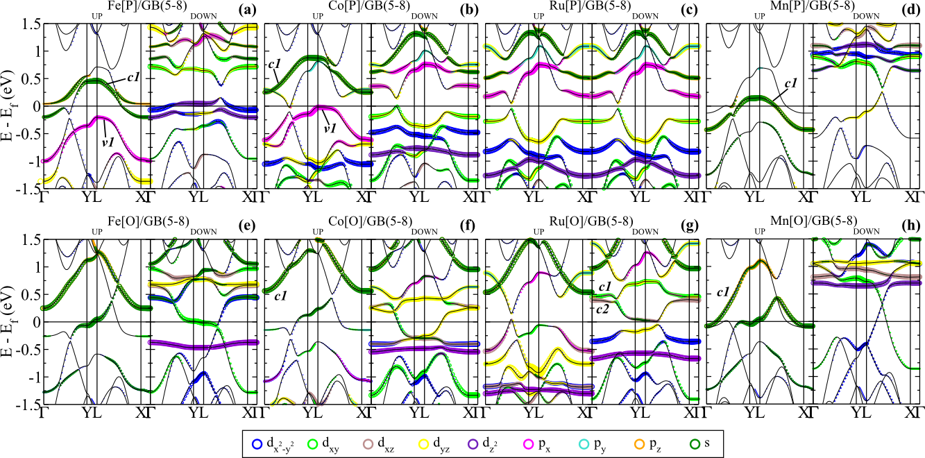
The electronic band structure along the Y direction of Mn[P]/ and Mn[O]/GB(5-8) [Figs. 4(d) and 4(h), respectively] suggest a half-metal character, in agreement with the previous theoretical studies Zhu et al. (2014); Obodo et al. (2015). However, along the LX direction of the spin-down channels, we find metallic states composed by Mn-3d states hybridized with the graphene- orbitals, giving rise to a Dirac-type cone at about eV. The formation such metallic bands, and the presence of a Dirac-type cone structure along the LX direction, are in agreement with our previous studies of nitrogen (n-type) doped GB(5-8) Brito et al. (2014). Indeed, by comparing the electronic band structure of pristine GB(5-8) [Fig. 2(d)], and Mn/GB(5-8), we verify a downshift of the DP, indicating a n-type doping of GB(5-8) upon the adsorption of both Mn[P] and Mn[O]. Thus, the presence of those metallic states rules out the half metallic properties of Mn/GB(5-8). We believe that further investigations are necessary to clarify this point.
III.3 Two TMs per GB unit cell
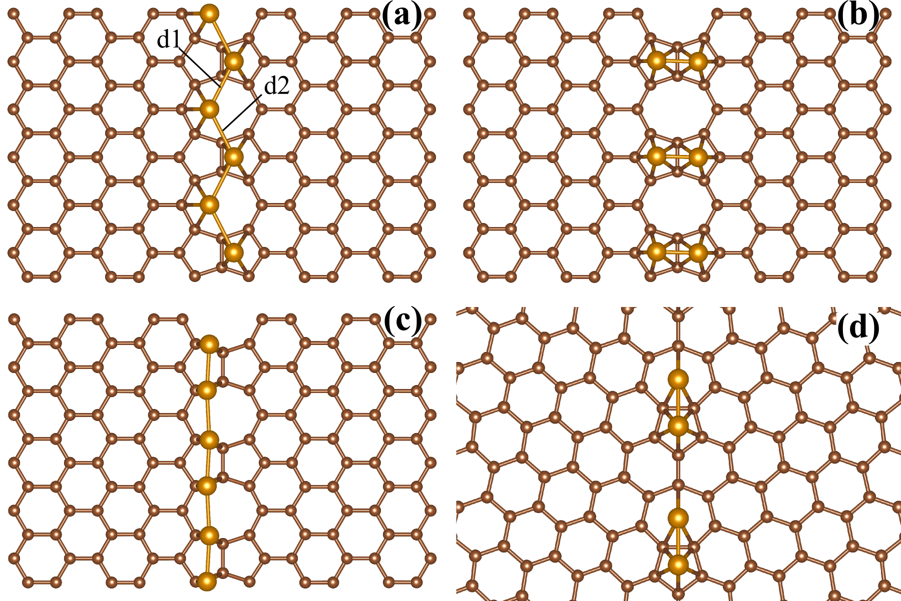
We next examine the energetic stability of TM/GB by increasing the concentration of TMs along the GB sites. For TM/GB(5-8), we have considered two different geometries, viz.: one TM adsorbed on the pentagonal ring and another on the octagonal ring (TM[PO]), and the two TMs adsorbed on the two pentagonal rings of GB(5-8) (TM[PP]). In Figs. 6(a) and 6(b) we present the calculated equilibrium geometries of TM[PO]/GB(5-8) and TM[PP]/GB(5-8), for TM = Mn and Fe. As shown in Table III, we find that the energetic stability of TM/GB(5-8) has been strengthened by increasing the concentration of the TMs along the GB sites; being the TM[PO] configuration more stable than TM[PP]. That is, the formation of TM-NLs has been favored upon the increase of the TM concentration along the GBs. For instance, Mn[PO]/ and Fe[PO]/GB(5-8) are more stable by 1.2 eV/atom than their counterparts Mn[P]/ and Fe[P]/GB(5-8). At the equilibrium geometry, we find that Mn[PO] and Fe[PO] form a zigzag structure [Fig. 6(a)].
| TM/GB(5-8) | m | |||
|---|---|---|---|---|
| PO | PP | PO | PP | |
| Mn | 2.51 | 2.14 | 0.10 | 0.00 |
| Fe | 2.93 | 2.86 | 3.14 | 3.17 |
| Co | 3.07 | 2.57 | 1.46 | 2.14 |
| Ru | 5.32 | 4.02 | 0.00 | 1.29 |
The energetic preference to the formation of TM-NLs along the GBs was also verified in TM/GB(5-7), Fig. 6(d). Here, we have considered one TM on the pentagonal site, and another on the heptagonal site, TM[PH]/GB(5-7). As shown in Table IV, the TM adsorption energies increase by 1 eV/atom when compared with their counterparts TM[P]/ and TM[H]/GB(5-7) systems. Those results for TM/GB(5-8) and TM/GB(5-7) provide further support to the recent experimental findings, related to the formation of linear structures of TMs on graphene ruled by GBs Kebailia et al. (2009); Kim et al. (2014); Yu et al. (2014a).
| TM/GB(5-7) | m | |
|---|---|---|
| Mn | 1.82 | 0.17 |
| Fe | 2.32 | 3.04 |
| Co | 2.45 | 1.37 |
| Ru | 3.92 | 1.61 |
The magnetic properties of those TM-NLs are mediated by the TM–TM and TM–GB interactions. We calculate the total energy difference between the AFM and FM states, for Mn[PO]/GB(5-8). We find that the AFM configuration is more stable by eV/atom. It is worth noting that the TMs adatoms siting on the P and O sites present different hybridizations with the (graphene) host, and thus we have different net magnetic moment for TM[P] and TM[O]. In this case, instead of AFM coupling, Mn[PO]/GB(5-8) presents a ferrimagnetic configuration, with a net magnetic moment of m = 0.1 . In Fig. 7(a) we present the spin-density for the ferrimagnetic Mn[PO]/GB(5-8). At the equilibrium geometry, we find Mn–Mn bond length of 2.76 Å [d1 = d2 = 2.76 Å in Fig. 6(a)].
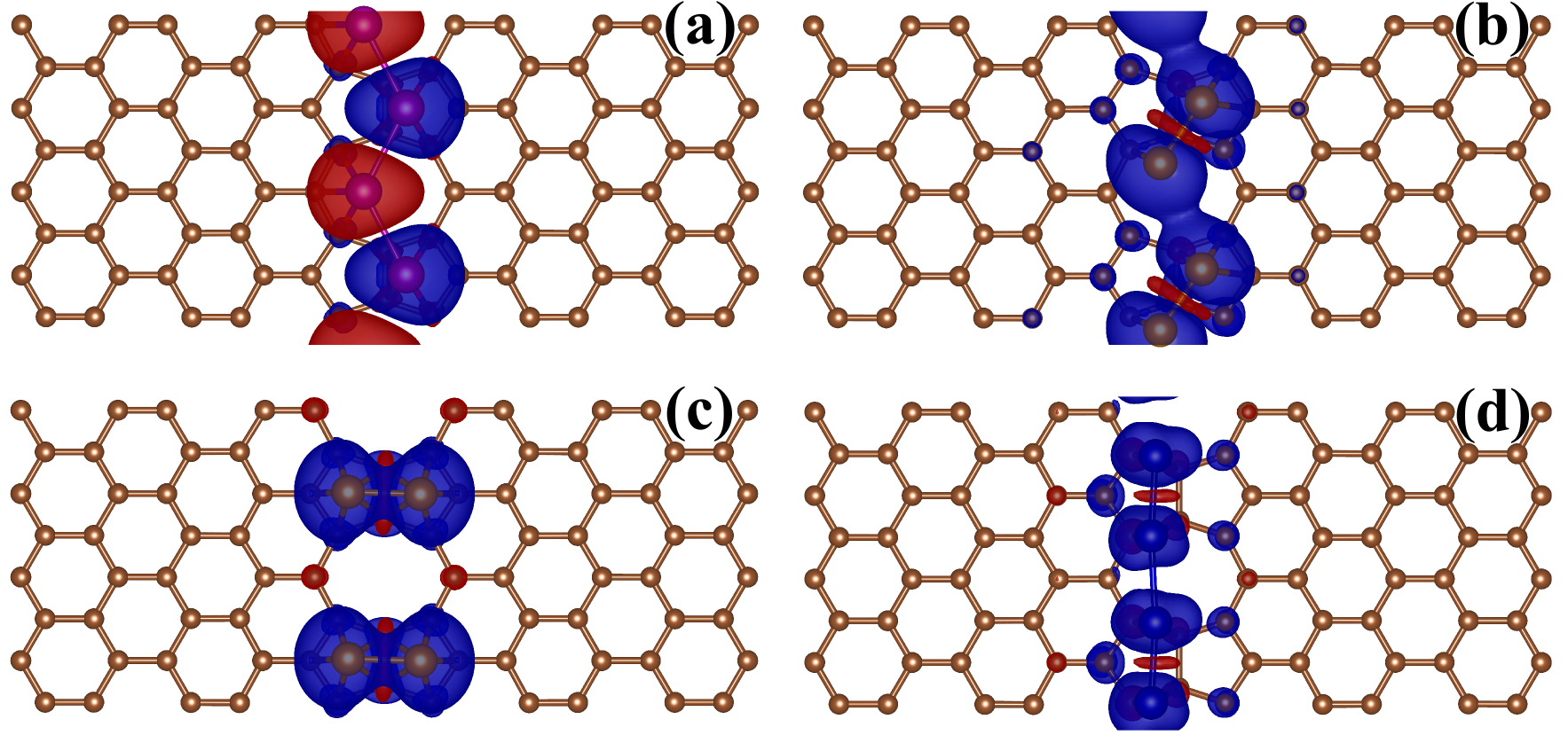
In contrast, both Fe[PO]/ and Fe[PP]/GB(5-8) are FM, with of 0.14 and 0.21 eV/atom, and m = 3.14 and 3.17 /Fe-atom, respectively. Figures 7(b) and 7(c) present the spin-density of the FM Fe[PO]/ and Fe[PP]/GB(5-8). At the equilibrium geometry (in the FM state), the Fe adatoms form a dimer-like structure, with a dimer bond length of 2.17 Å and dimer separation of 3.36 Å, d1 and d2 in Fig. 6(a). It is worth noting that the spin polarization are localized on the Fe adatoms, with almost negligible contribution from the host (neighboring) C atoms. Fe[PO]/GB(5-8) and Fe[PP]/GB(5-8) are very close in energy, Table III. The Fe-dimers of Fe[PP]/GB(5-8) present a dimer bond length of 2.37 and 2.13 Å for the FM and AFM states, Fig. 6(b). By considering isolated Fe-dimers, we find an equilibrium Fe–Fe distance of 1.99 and 2.24 Å for the FM and AFM states, where the FM configuration (m = 2.8 /Fe-atom) is more stable by 1.35 eV than the AFM state, which is in agreement with previous theoretical study Lebon et al. (2008). Further comparisons with isolated Fe-dimers suggest that the increase of the Fe-dimer bond length, when adsorbed along the GB sites, contributes to the increase of the net magnetic moment of Fe adatoms in Fe[PO]/ and Fe[PP]/GB(5-8), with respect to the isolated Fe-dimers (2.8 3.2 ) Mokrousov et al. (2007).
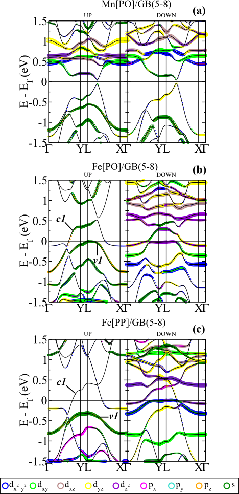
The energy bands of spin-up and -down channels of the ferrimagnetic Mn[PO]/GB(5-8) system are almost the same, Fig. 8(a). The differences are due to the different adsorption sites of Mn adatoms, namely Mn[P] and Mn[O]. Here, for both spin channels, we find a Dirac-like structure along the L-X direction, as we obtained for the spin-down channels of Mn[P]/ and Mn[O]/GB(5-8), Fig. 4(d) and 4(h). Those Dirac-like states are mostly ruled by the graphene- orbitals, with small contributions from the Mn-4s and -3d states. The magnetic moment of each Mn adatom, m=4.08 and 4.18 for Mn[P] and Mn[O], respectively, are mostly due to the unpaired Mn-3d electrons; where the occupied (unoccupied) Mn-3d orbitals lie at about eV ( eV).
In Figs. 8(b) and 8(c) we present the electronic band structure of the FM Fe[PO]/ and Fe[PP]/GB(5-8) systems. Near the Fermi level, the electronic band structure of the pristine GB(5-8) has been somewhat preserved for the spin-up channel of both systems. In Fe[PO]/GB(5-8), the electronic states near the edge of the Brillouin zone are characterized by Fe-4s orbital hybridized with the orbitals of the graphene layer, energy band in Fig. 8(b). Whereas the electronic contribution of the Fe adatoms in is negligible for Fe[PP]/GB(5-8), Fig. 8(c); indicating that the (spin-up) electronic transport in Fe[PP]/GB(5-8) will be mediated by the orbitals of graphene. For both systems, the DP lies below the Fermi level, suggesting a net electronic charge transfer to the graphene sheet (n-type doping). In contrast, the spin-down channels are characterized by nearly dispersionless energy bands predominantly composed by Fe-3d orbitals, and the Dirac cone feature has been washed out. Thus, similarly to the previous Fe[P]/ and Fe[O]/GB(5-8) structures, we may expect a spin-anisotropy on the electronic transport along the FM Fe/GB(5-8) system. On the other hand, such a spin-anisotropy has been suppressed in AFM Fe[PO]/ and Fe[PP]/GB(5-8), where we find semiconductor systems (not shown). Indeed, spin-depend electronic current, perpendicular to the GB sites, has been proposed for other TM geometries on Gb(5-8) Yu et al. (2014b).
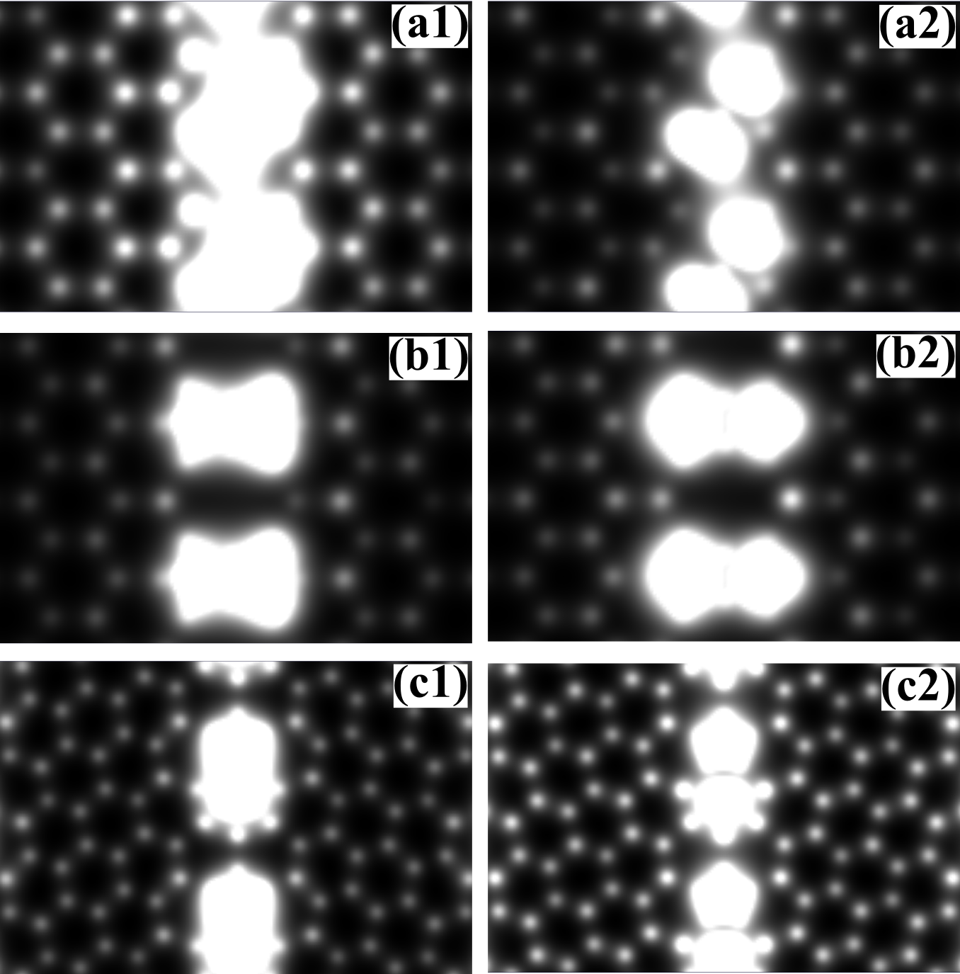
In Fig. 9(a) and 9(b) we present the simulated STM images of Fe[PO]/ and Fe[PP]/GB(5-8) within an energy interval of 1 eV with respect to the Fermi level. In Fe[PO]/GB(5-8), the occupied states ( eV) are characterized by the formation of a bright line along the Fe adsorbed GB sites [Fig. 9(a1)], whereas for the empty states ( eV) we find bright spots lying on the Fe adatoms, Fig. 9(a2). The STM pictures for the occupied and empty states [Figs. 9(b1) and 9(b2)] are quite similar for Fe[PP]/GB(5-8); characterized by the bright Fe dimers perpendicularly to the GB line, which is in agreement with the localized feature of the Fe orbitals in Fe[PP]/GB(5-8). The formation of bright Fe dimers has been also verified in Fe/GB(5-7), Figs. 9(c1) and 9(c2). Somewhat similar STM pictures are expected to the other TM/GB systems. Here, the formation of bright lines along the GB sites, adsorbed by TMs, is in accordance with the recent experimental STM images Kebailia et al. (2009); Yu et al. (2014a); Kim et al. (2014).
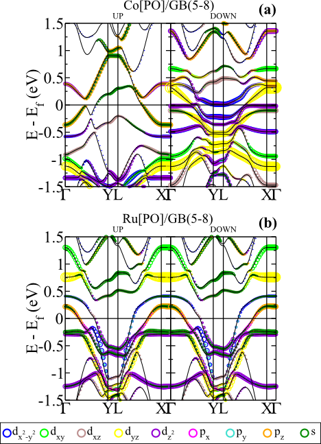
The equilibrium geometries of Co[PO] and Ru[PO]/GB(5-8) are different than those obtained for Mn[PO] and Fe[PO]/GB(5-8). As shown in Fig. 6(c), (i) the Co (Ru) adatoms form a nearly linear Co-NL (Ru-NL) with d1 = 2.36 Å and d2 = 2.55 Å (d1 = 2.44 Å and d2 = 2.48 Å), and (ii) the Co and Ru adatoms lie on the C–C bridge sites along the GB. Co[PO]/GB(5-8) present a FM state; where the spin-density is mainly localized on the Co adatoms, Fig. 7(d). Similarly to the other Fe/GB systems, the electronic band structure of Co[PO]/GB(5-8) [Fig. 10(a)] suggests a spin dependent electronic current. The electronic transport along the Co-NLs will be ruled by the spin-up channels, since the the spin-down electrons will face scattering processes due to the Co-3d localized states near the Fermi level. As shown in Fig. 10(a), (i) the energy bands on the spin-up channel (near the Fermi level) are characterized by a strong hybridization between the 3pz and 4s orbitals of the Co adatoms with the bands of the graphene host. Whereas, (ii) for the spin-down channels, we find a set of flat bands, mostly composed by localized Co-3d and -3d states. It is worth noting that (i) and (ii) were already verified in Co/GB systems composed by a single Co adatoms per grain boundary unit cell, Figs. 4 and 5. Here, we find that the formation of those dispersionless energy bands near the Fermi level [(ii)] has been strengthened, by increasing the concentration of Co adatoms along the GB sites. Meanwhile, the Dirac cone structure has been suppressed for both spin-channels in Ru[PO]/GB(5-8), Fig. 10(b). The electronic band structure of Ru[PO]/GB(5-8) can be characterized by the formation of metallic bands along the -Y and L-X direction, composed by Ru-4d and graphene orbitals.

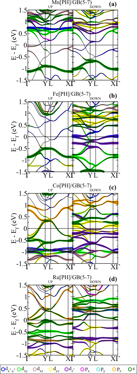
The Mn[PH]/GB(5-7) system presents a ferrimagnetic state as the lowest energy configuration. As shown in Fig. 11(a), the spin densities on the Mn[P] and Mn[H] adatoms are slightly different, giving rise to a net magnetic moment of 0.16 . The magnetic moment of each Mn adatom, m=4.30 and 4.25 for Mn[P] and Mn[O], are mostly due to the unpaired Mn-3d electrons; with the occupied (unoccupied) Mn-3d orbitals lying at about eV ( eV). In Fig. 12(a) we present the electronic band structure of Mn[PO]/GB(5-7). We find, for both spin channels, metallic bands for wave vectors along the -Y direction, composed by Mn-3d and -3dxz states hybridized with the host orbitals.
In contrast, the other TM[PH]/GB(5-7) systems (TM = Fe, Co and Ru) are more stable at the FM state. In Fig. 11(b)–11(d) we present the (ground state) spin-densities of Fe[PH]/, Co[PH]/,and Ru[PH]/GB(5-7); where we find the formation of dimer-like structures along the GB sites. However, the electronic structure of those TM[PH]/GB(5-7) systems are quite different. In Fe[PO]/GB(5-7) [Fig. 12(b)], the electronic contribution of Fe adatoms for the spin-up metallic states is negligible, whereas for the spin-down channel, the Fe-3d orbitals give rise to dispersionless energy bands near the Fermi level. In contrast, in Co[PH]/GB(5-7), the Co-4s and -3dyz orbitals contribute to the formation of (spin-up) metallic bands along the -Y and L-X directions [Fig. 12(c)]; indicating a charge density overlap, of Co-4s and -3dyz orbitals, between the nearest neighbor Co-dimers along the GB sites. Whereas, for the spin-down energy bands, we find a set of dispersionless energy bands ruled by the Co-3d orbitals. Such a charge density overlap is somewhat reduced for the Ru-dimers in Ru[PH]/GB(5-7). As shown in Fig. 12(d), there are no metallic bands for both spin channels of FM Ru[PO]/GB(5-7). The electronic bands near the Fermi level present an energy dispersion of 0.3 eV, and are mostly composed by Ru-5s and -4 orbitals.
In summary, our results show that the formation of TM-NLs ruled by GBs in graphene is a energetically favorable process; where the electronic struture of those TM-NLs is constrained by (i) the equilibrium geometry of the TM adatoms (for instance, Fe[PP]/ and Fe[PO]/GB(5-8)]), well as (ii) the atomic geometry of the GB sites like in Fe[P]/GB(5-8) and Fe[P]/GB(5-7).
IV Conclusions
Based on the ab initio DFT calculations, we find energetically stable TM nanolines in graphene ruled by GBs (TM = Mn, Fe, Co, and Ru). The stability of those TM nanolines is strengthened upon TM–TM chemical interactions. Our total energy results provide further support to the recent experimental findings of TM nanolines in graphene patterned by GBs. At the equilibrium geometry, we find ferromagnetic (ferrimagnetic) Fe and Co (Mn) nanolines, while the magnetic state of the Ru nanolines depends on the (local) adsorption geometry. Through extensive electronic band structure calculations, we verify that the most of TM nanolines are (i) metallic, and (ii) spin-polarized with quite different spin-up and spin-down electronic band structures. In (ii) we can infer a spin-anisotropy for the electronic current along those TM nanolines.
Acknowledgements.
The authors acknowledge financial support from the Brazilian agencies CNPq/INCT and FAPEMIG, and the computational support from CENAPAD/SP.References
- Choi et al. (2000) H. J. Choi, J. Ihm, S. G. Loiue, and M. L. Cohen, Phys. Rev. Lett. 84, 2917 (2000).
- Meyer et al. (2008) J. C. Meyer, C. Kisielowski, R. Erni, M. D. Rossell, M. F. Crommie, and A. Zettl, Nano Letters 8, 3582 (2008).
- Lusk and Carr (2008) M. T. Lusk and L. D. Carr, Phys. Rev. Lett. 100, 175503 (2008).
- Lehtinen et al. (2015) O. Lehtinen, N. Vats, G. Algara-Siller, P. Knyrim, and U. Kaiser, Nano Letters 15, 235 (2015).
- Simonis et al. (2002) P. Simonis, G. Goffaux, P. A. Thiry, L. P. Biro, P. Lambin, and V. Meunier, Surf. Sci. 511, 319 (2002).
- Yazyev and Louie (2010a) O. V. Yazyev and S. G. Louie, Phys. Rev. B 81, 195420 (2010a).
- Huang et al. (2011) P. Y. Huang, C. S. Ruiz-Vargas, A. M. van der Zande, W. S. Whitney, M. P. Levendorf, J. W. Kevek, S. Garg, J. S. Alden, C. J. Hustedt, Y. Zhu, J. Park, P. L. McEuen, and D. A. Muller, Nature 469, 389 (2011).
- Yazyev and Louie (2010b) O. V. Yazyev and S. G. Louie, Nature Materials 9, 806 (2010b).
- Botello-Mendéz et al. (2011) A. R. Botello-Mendéz, X. Declerck, M. Terrones, H. Terrones, and J. Charlier, Nanoscale 3, 2868 (2011).
- Lahiri et al. (2010) J. Lahiri, Y. Lin, P. Bozkurt, I. I. Oleynik, and M. Batzill, Nature Nanotechnology 5, 326 (2010).
- Kou et al. (2011) L. Kou, C. Tang, W. Guo, and C. Chen, ACS Nano 5, 1012 (2011).
- Alexandre et al. (2012) S. S. Alexandre, A. D. Lúcio, A. H. C. Neto, and R. W. Nunes, Nano Lett. 12, 5097 (2012).
- Brito et al. (2014) W. H. Brito, H. Chacham, R. Kagimura, and R. H. Miwa, Nanotechnology 25, 245706 (2014).
- Cretu et al. (2010) O. Cretu, A. V. Krasheninnikov, J. A. Rodríguez-Manzo, L. Sun, R. M. Nieminen, , and F. Banhart, Phys. Rev. Lett. 105, 196102 (2010).
- Kebailia et al. (2009) N. Kebailia, S. Benrezzak, P. Cahuzac, A. Masson, and C. Brechignac, European Physical Journal D 52, 115 (2009).
- Yu et al. (2014a) S. U. Yu, B. Park, Y. Cho, S. Hyun, J. K. Kim, and K. S. Kim, ACS Nano 8, 8662 (2014a).
- Kim et al. (2014) K. Kim, H.-B.-R. Lee, R. W. Johnson, J. T. Tanskanen, N. Liu, M.-G. Kim, C. Pang, C. Ahn, S. F. Bent, and Z. Bao, Nature Communications 5, 4781 (2014).
- Zhu et al. (2014) Z. Zhu, W. Chen, Q. Sun, and Y. Jia, J. Phys. D: Appl. Phys. 47, 055303 (2014).
- Obodo et al. (2015) J. T. Obodo, M. Upadhyay Kahaly, and U. Schwingenschlg, Phys. Rev. B 91, 014413 (2015).
- Martins et al. (2007) T. B. Martins, R. H. Miwa, A. J. R. da Silva, and A. Fazzio, Phys. Rev. Lett. 98, 196803 (2007).
- Rigo et al. (2009) V. A. Rigo, T. B. Martins, A. J. R. da Silva, A. Fazzio, and R. H. Miwa, Phys. Rev. B 79, 075435 (2009).
- Kresse and Furthmller (1996) G. Kresse and J. Furthmller, Comput. Mater. Sci. 6, 15 (1996).
- Perdew et al. (1996) J. P. Perdew, K. Burke, and M. Ernzerhof, Phys. Rev. Lett. 77, 3865 (1996).
- Monkhorst and Pack (1976) H. J. Monkhorst and J. D. Pack, Phys. Rev. B 13, 5188 (1976).
- Kresse and Joubert (1999) G. Kresse and D. Joubert, Phys. Rev. B 59, 1759 (1999).
- Sevinçli et al. (2008) H. Sevinçli, T. Topsakal, E. Durgun, and S. Ciraci, Phys. Rev. B 77, 195434 (2008).
- Chan et al. (2008) K. T. Chan, J. B. Neaton, and M. L. Cohen, Phys. Rev. B 77, 235430 (2008).
- Wang et al. (2009) Q. E. Wang, F. H. Wang, J. X. Shang, and Y. S. Zhou, J. Phys. Condens. Matter 21, 485506 (2009).
- Mera Acosta et al. (2014) C. Mera Acosta, Matheus P. Lima, R. H. Miwa, Antônio J. R. da Silva, and A. Fazzio, Phys. Rev. B 89, 155438 (2014).
- Brito et al. (2011) W. H. Brito, R. Kagimura, and R. H. Miwa, Appl. Phys. Lett. 98, 213107 (2011).
- Yu et al. (2014b) G. Yu, M. Zhu, and Y. Zheng, J. mater. Chem.C 2, 9767 (2014b).
- Blchl (1994) P. E. Blchl, Phys. Rev. B 50, 17953 (1994).
- Vanderbilt (1990) D. Vanderbilt, Phys. Rev. B 41, 7892 (1990).
- Giannozzi et al. (2009) P. Giannozzi et al., J. Phys.: Condens. Matter 21, 395502 (2009).
- (35) We have used a energy cutoff of 35 Ry for the plane wave basis set, and 280 Ry to describe the total charge density. The Brillouin zone was sampled by using a grid of 1101.
- Henkelman et al. (2000) G. Henkelman, B. P. Uberuaga, and H. Jónsson, J. Chem. Phys. 113, 9901 (2000).
- Lebon et al. (2008) A. Lebon, A. Mokrani, and A. Vega, Phys. Rev. B 78, 184401 (2008).
- Mokrousov et al. (2007) Y. Mokrousov, G. Bihlmayer, S. Blgel, and S. Heinze, Phys. Rev. B 75, 104413 (2007).