Multiple-Input Multiple-Output OFDM with Index Modulation

Ertuğrul Başar E. Başar is with Istanbul Technical University, Faculty of Electrical and Electronics Engineering, 34469, Istanbul, Turkey. e-mail: basarer@itu.edu.tr. This work was supported by the Scientific Research Projects Foundation, Istanbul Technical University.©2015 IEEE. Personal use of this material is permitted. Permission from IEEE must be obtained for all other uses, in any current or future media, including reprinting/republishing this material for advertising or promotional purposes, creating new collective works, for resale or redistribution to servers or lists, or reuse of any copyrighted component of this work in other works.Digital Object Identifier 10.1109/LSP.2015.2475361
Abstract

Orthogonal frequency division multiplexing with index modulation (OFDM-IM) is a novel multicarrier transmission technique which has been proposed as an alternative to classical OFDM. The main idea of OFDM-IM is the use of the indices of the active subcarriers in an OFDM system as an additional source of information. In this work, we propose multiple-input multiple-output OFDM-IM (MIMO-OFDM-IM) scheme by combining OFDM-IM and MIMO transmission techniques. The low complexity transceiver structure of the MIMO-OFDM-IM scheme is developed and it is shown via computer simulations that the proposed MIMO-OFDM-IM scheme achieves significantly better error performance than classical MIMO-OFDM for several different system configurations.

Index Terms:
OFDM, index modulation, MIMO systems, MMSE detection, V-BLAST, 5G wireless networks.

I Introduction

Orthogonal frequency division multiplexing (OFDM) has become the most popular multicarrier signaling format for high-speed wireless communications and has been included in many standards such as Long Term Evolution (LTE), IEEE 802.11 wireless local area network (WLAN) and digital video broadcasting (DVB). Due to its efficient implementation and robustness to the frequency selectivity, OFDM and its combination with multiple-input multiple-output (MIMO) systems unsurprisingly appears as a strong alternative for 5G networks [1].

OFDM with index modulation (OFDM-IM) is a recently proposed novel scheme which transmits information not only by M𝑀M-ary constellation symbols, but also by the indices of the active subcarriers which are activated according to the incoming information bits [2]. Subcarrier index modulation techniques for OFDM [2, 3, 4] have attracted considerable attention from researchers and have been investigated in some recent studies due to interesting trade-offs they offer in error performance and spectral efficiency compared to classical OFDM systems [5, 6, 7, 8, 9, 10, 11]. The bit error probability of OFDM-IM is analytically derived in [5]. The spectral efficiency of OFDM-IM is improved by selecting the active subcarriers in a more flexible way in [6], where index modulation is applied for both in-phase and quadrature components of the subcarriers. In [7] and [8], the authors deal with the problem of selecting the optimal number of active subcarriers in OFDM-IM. More recently, OFDM-IM is combined with coordinate interleaving to achieve additional diversity gains in [9]. However, the combination of OFDM-IM and MIMO transmission techniques remains an open and interesting research problem.

In this study, we propose MIMO-OFDM with index modulation (MIMO-OFDM-IM) as an efficient alternative multicarrier transmission scheme for 5G networks by combining MIMO and OFDM-IM transmission techniques. In the proposed scheme, each transmit antenna transmits its own OFDM-IM frame as in Vertical Bell Labs layered space-time (V-BLAST) scheme [12], and at the receiver side, these OFDM-IM frames are separated and demodulated using a novel and low complexity minimum mean square error (MMSE) detection and log-likelihood ratio (LLR) calculation based detector. It is shown via computer simulations that the MIMO-OFDM-IM scheme achieves significantly better bit error rate (BER) performance than classical V-BLAST type MIMO-OFDM for several MIMO configurations.

The rest of the letter is organized as follows. In Section II, the system model of MIMO-OFDM-IM is presented. In Section III, receiver structure of the MIMO-OFDM-IM scheme is given. Simulation results are provided in Section IV. Finally, Section V concludes the letter.***Notation: Bold, lowercase and capital letters are used for column vectors and matrices, respectively. (𝐀)tsubscript𝐀𝑡(\mathbf{A})_{t} and (𝐀)t,tsubscript𝐀𝑡𝑡(\mathbf{A})_{t,t} denote the t𝑡tth column and the t𝑡tth main diagonal element of 𝐀𝐀\mathbf{A}, respectively. ()Tsuperscript𝑇{{\left(\cdot\right)}^{T}} and ()Hsuperscript𝐻{{\left(\cdot\right)}^{H}} denote transposition and Hermitian transposition, respectively. 𝐈Nsubscript𝐈𝑁\mathbf{I}_{N} is the identity matrix with dimensions N×N𝑁𝑁N\times N and diag()diag\mbox{diag}\left(\cdot\right) denotes a diagonal matrix. \left\|\cdot\right\| stands for the Euclidean norm. The probability of an event is denoted by P()𝑃{{P}}\left(\cdot\right) and E{}𝐸E\left\{\cdot\right\} stands for expectation. X𝒞𝒩(0,σX2)similar-to𝑋𝒞𝒩0superscriptsubscript𝜎𝑋2X\sim\mathcal{CN}\left(0,\sigma_{X}^{2}\right) represents the distribution of a circularly symmetric complex Gaussian r.v. X𝑋X with variance σX2superscriptsubscript𝜎𝑋2\sigma_{X}^{2}. C(N,K)𝐶𝑁𝐾C\left(N,K\right) stands for the binomial coefficient and \lfloor\cdot\rfloor is the floor function. 𝒮𝒮\mathcal{S} denotes M𝑀M-ary signal constellation. \mathbb{C} denotes the ring of complex numbers.

II System Model of MIMO-OFDM-IM

Refer to caption
Figure 1: Transceiver Structure of the MIMO-OFDM-IM Scheme for a T×R𝑇𝑅T\times R MIMO System

The block diagram of the MIMO-OFDM-IM transceiver is shown in Fig. 1. We consider a MIMO system employing T𝑇T transmit and R𝑅R receive antennas. As seen from Fig. 1, for the transmission of each frame, a total of mT𝑚𝑇mT information bits enter the MIMO-OFDM-IM transmitter. These mT𝑚𝑇mT bits are first split into T𝑇T groups and the corresponding m𝑚m bits are processed in each branch of the transmitter by the OFDM index modulators. The incoming m𝑚m information bits are used to form the NF×1subscript𝑁𝐹1N_{F}\times 1 OFDM-IM block 𝐱t=[xt(1)xt(2)xt(NF)]T,t=1,2,,Tformulae-sequencesubscript𝐱𝑡superscriptmatrixsubscript𝑥𝑡1subscript𝑥𝑡2subscript𝑥𝑡subscript𝑁𝐹𝑇𝑡12𝑇\mathbf{x}_{t}=\begin{bmatrix}x_{t}(1)&x_{t}(2)&\cdots&x_{t}(N_{F})\end{bmatrix}^{T},t=1,2,\ldots,T in each branch of the transmitter, where NFsubscript𝑁𝐹N_{F} is the size of the fast Fourier transform (FFT) and xt(nf){0,𝒮},nf=1,2,,NFformulae-sequencesubscript𝑥𝑡subscript𝑛𝑓0𝒮subscript𝑛𝑓12subscript𝑁𝐹x_{t}(n_{f})\in\left\{0,\mathcal{S}\right\},n_{f}=1,2,\ldots,N_{F}. According to the OFDM-IM principle [2], these m𝑚m bits are split into G𝐺G groups each containing p=p1+p2𝑝subscript𝑝1subscript𝑝2p=p_{1}+p_{2} bits, which are used to form OFDM-IM subblocks 𝐱tg=[xtg(1)xtg(2)xtg(N)]T,g=1,2,,Gformulae-sequencesuperscriptsubscript𝐱𝑡𝑔superscriptmatrixsuperscriptsubscript𝑥𝑡𝑔1superscriptsubscript𝑥𝑡𝑔2superscriptsubscript𝑥𝑡𝑔𝑁𝑇𝑔12𝐺\mathbf{x}_{t}^{g}=\begin{bmatrix}x_{t}^{g}(1)&x_{t}^{g}(2)&\cdots&x_{t}^{g}(N)\end{bmatrix}^{T},g=1,2,\ldots,G of length N=NF/G𝑁subscript𝑁𝐹𝐺N=N_{F}/G, where xtg(n){0,𝒮},n=1,2,,Nformulae-sequencesuperscriptsubscript𝑥𝑡𝑔𝑛0𝒮𝑛12𝑁x_{t}^{g}(n)\in\left\{0,\mathcal{S}\right\},n=1,2,\ldots,N. According to the corresponding p1=log2(C(N,K))subscript𝑝1subscript2𝐶𝑁𝐾p_{1}=\lfloor\log_{2}\left(C\left(N,K\right)\right)\rfloor bits, only K𝐾K out of N𝑁N available subcarriers are selected as active by the index selector at each subblock g𝑔g, while the remaining NK𝑁𝐾N-K subcarriers are inactive and set to zero. On the other hand, the remaining p2=Klog2(M)subscript𝑝2𝐾subscript2𝑀p_{2}=K\log_{2}(M) bits are mapped onto the considered M𝑀M-ary signal constellation. Therefore, unlike classical MIMO-OFDM, 𝐱t,t=1,2,,Tformulae-sequencesubscript𝐱𝑡𝑡12𝑇\mathbf{x}_{t},t=1,2,\ldots,T contains some zero terms whose positions carry information for MIMO-OFDM-IM.

In this study, active subcarrier index selection is performed by the reference look-up tables at OFDM index modulators of the transmitter. The considered reference look-up tables for N=4,K=2formulae-sequence𝑁4𝐾2N=4,K=2 and N=4,K=3formulae-sequence𝑁4𝐾3N=4,K=3 are given in Tables I and II, respectively, where sk𝒮subscript𝑠𝑘𝒮s_{k}\in\mathcal{S} for k=1,2,K𝑘12𝐾k=1,2,\ldots K. As seen from Table I, for N=4𝑁4N=4 and K=2𝐾2K=2, the incoming p1=2subscript𝑝12p_{1}=2 bits can be used to select the indices of the two active subcarriers out of four available subcarriers according to the reference look-up table of size C=2p1=4𝐶superscript2subscript𝑝14C=2^{p_{1}}=4.

TABLE I: Reference Look-up Table for N=4,K=2formulae-sequence𝑁4𝐾2N=4,K=2 and p1=2subscript𝑝12p_{1}=2
Bits Indices OFDM-IM subblocks (𝐱tg)Tsuperscriptsuperscriptsubscript𝐱𝑡𝑔𝑇(\mathbf{x}_{t}^{g})^{T}
[0   0]delimited-[]00[0\,\,\,0] {1,3}13\left\{1,3\right\} [s10s20]matrixsubscript𝑠10subscript𝑠20\begin{bmatrix}s_{1}&0&s_{2}&0\end{bmatrix}
[0   1]delimited-[]01[0\,\,\,1] {2,4}24\left\{2,4\right\} [0s10s2]matrix0subscript𝑠10subscript𝑠2\begin{bmatrix}0&s_{1}&0&s_{2}\end{bmatrix}
[1   0]delimited-[]10[1\,\,\,0] {1,4}14\left\{1,4\right\} [s100s2]matrixsubscript𝑠100subscript𝑠2\begin{bmatrix}s_{1}&0&0&s_{2}\end{bmatrix}
[1   1]delimited-[]11[1\,\,\,1] {2,3}23\left\{2,3\right\} [0s1s20]matrix0subscript𝑠1subscript𝑠20\begin{bmatrix}0&s_{1}&s_{2}&0\end{bmatrix}
TABLE II: Reference Look-up Table for N=4,K=3formulae-sequence𝑁4𝐾3N=4,K=3 and p1=2subscript𝑝12p_{1}=2
Bits Indices OFDM-IM subblocks (𝐱tg)Tsuperscriptsuperscriptsubscript𝐱𝑡𝑔𝑇(\mathbf{x}_{t}^{g})^{T}
[0   0]delimited-[]00[0\,\,\,0] {1,2,3}123\left\{1,2,3\right\} [s1s2s30]matrixsubscript𝑠1subscript𝑠2subscript𝑠30\begin{bmatrix}s_{1}&s_{2}&s_{3}&0\end{bmatrix}
[0   1]delimited-[]01[0\,\,\,1] {1,2,4}124\left\{1,2,4\right\} [s1s20s3]matrixsubscript𝑠1subscript𝑠20subscript𝑠3\begin{bmatrix}s_{1}&s_{2}&0&s_{3}\end{bmatrix}
[1   0]delimited-[]10[1\,\,\,0] {1,3,4}134\left\{1,3,4\right\} [s10s2s3]matrixsubscript𝑠10subscript𝑠2subscript𝑠3\begin{bmatrix}s_{1}&0&s_{2}&s_{3}\end{bmatrix}
[1   1]delimited-[]11[1\,\,\,1] {2,3,4}234\left\{2,3,4\right\} [0s1s2s3]matrix0subscript𝑠1subscript𝑠2subscript𝑠3\begin{bmatrix}0&s_{1}&s_{2}&s_{3}\end{bmatrix}

The OFDM index modulators in each branch of the transmitter obtain the OFDM-IM subblocks first and then concatenate these G𝐺G subblocks to form the main OFDM blocks 𝐱t,t=1,2,,Tformulae-sequencesubscript𝐱𝑡𝑡12𝑇\mathbf{x}_{t},t=1,2,\ldots,T. In order to transmit the elements of the subblocks from uncorrelated channels, G×N𝐺𝑁G\times N block interleavers (Π)Π(\Pi) are employed at the transmitter. The block interleaved OFDM-IM frames 𝐱~t,t=1,2,,Tformulae-sequencesubscript~𝐱𝑡𝑡12𝑇\mathbf{\tilde{x}}_{t},t=1,2,\ldots,T are processed by the inverse FFT (IFFT) operators to obtain 𝐪~t,t=1,2,,Tformulae-sequencesubscript~𝐪𝑡𝑡12𝑇\mathbf{\tilde{q}}_{t},t=1,2,\ldots,T. We assume that the time-domain OFDM symbols are normalized to have unit energy, i.e., E{𝐪~tH𝐪~t}=NF𝐸superscriptsubscript~𝐪𝑡𝐻subscript~𝐪𝑡subscript𝑁𝐹E\left\{\mathbf{\tilde{q}}_{t}^{H}\mathbf{\tilde{q}}_{t}\right\}=N_{F} for all t𝑡t. After the addition of cyclic prefix of Cpsubscript𝐶𝑝C_{p} samples, parallel-to-serial and digital-to-analog conversions, the resulting signals sent simultaneously from T𝑇T transmit antennas over a frequency selective Rayleigh fading MIMO channel, where 𝐠r,tL×1subscript𝐠𝑟𝑡superscript𝐿1\mathbf{g}_{r,t}\in\mathbb{C}^{L\times 1} represents the L𝐿L-tap wireless channel between the transmit antenna t𝑡t and the receive antenna r𝑟r, whose elements are independent and identically distributed with 𝒞𝒩(0,1L)𝒞𝒩01𝐿\mathcal{CN}(0,\frac{1}{L}). Assuming the wireless channels remain constant during the transmission of a MIMO-OFDM-IM frame and Cp>Lsubscript𝐶𝑝𝐿C_{p}>L, after removal of the cyclic prefix and performing FFT operations in each branch of the receiver, the input-output relationship of the MIMO-OFDM-IM scheme in the frequency domain is obtained as

𝐲~r=t=1Tdiag(𝐱~t)𝐡r,t+𝐰rsubscript~𝐲𝑟superscriptsubscript𝑡1𝑇diagsubscript~𝐱𝑡subscript𝐡𝑟𝑡subscript𝐰𝑟\mathbf{\tilde{y}}_{r}=\sum\nolimits_{t=1}^{T}\mbox{diag}\left(\mathbf{\tilde{x}}_{t}\right)\mathbf{h}_{r,t}+\mathbf{w}_{r} (1)

for r=1,2,,R𝑟12𝑅r=1,2,\ldots,R, where 𝐲~r=[y~r(1)y~r(2)y~r(NF)]Tsubscript~𝐲𝑟superscriptmatrixsubscript~𝑦𝑟1subscript~𝑦𝑟2subscript~𝑦𝑟subscript𝑁𝐹𝑇\mathbf{\tilde{y}}_{r}=\begin{bmatrix}\tilde{y}_{r}(1)&\tilde{y}_{r}(2)&\cdots&\tilde{y}_{r}(N_{F})\end{bmatrix}^{T} is the vector of the received signals for receive antenna r𝑟r, 𝐡r,tNF×1subscript𝐡𝑟𝑡superscriptsubscript𝑁𝐹1\mathbf{h}_{r,t}\in\mathbb{C}^{N_{F}\times 1} represents the frequency response of the wireless channel between the transmit antenna t𝑡t and receive antenna r𝑟r, and 𝐰rNF×1subscript𝐰𝑟superscriptsubscript𝑁𝐹1\mathbf{w}_{r}\in\mathbb{C}^{N_{F}\times 1} is the vector of noise samples. The elements of 𝐡r,tsubscript𝐡𝑟𝑡\mathbf{h}_{r,t} and 𝐰rsubscript𝐰𝑟\mathbf{w}_{r} follow 𝒞𝒩(0,1)𝒞𝒩01\mathcal{CN}\left(0,1\right) and 𝒞𝒩(0,N0,F)𝒞𝒩0subscript𝑁0𝐹\mathcal{CN}\left(0,N_{0,F}\right) distributions, respectively, where N0,Fsubscript𝑁0𝐹N_{0,F} denotes the variance of the noise samples in the frequency domain, which is related to the variance of the noise samples in the time domain as N0,T=(NF/(KG))N0,Fsubscript𝑁0𝑇subscript𝑁𝐹𝐾𝐺subscript𝑁0𝐹N_{0,T}=(N_{F}/(KG))N_{0,F}. We define the signal-to-noise ratio (SNR) as SNR=Eb/N0,TSNRsubscript𝐸𝑏subscript𝑁0𝑇\mathrm{SNR}=E_{b}/N_{0,T} where Eb=(NF+Cp)/msubscript𝐸𝑏subscript𝑁𝐹subscript𝐶𝑝𝑚E_{b}=(N_{F}+C_{p})/m [joules/bit] is the average transmitted energy per bit. The spectral efficiency of the MIMO-OFDM-IM scheme is mT/(NF+Cp)𝑚𝑇subscript𝑁𝐹subscript𝐶𝑝mT/(N_{F}+C_{p}) [bits/s/Hz], which is equal to T𝑇T times that of the OFDM-IM scheme.

III Detection of MIMO-OFDM-IM Scheme

After block deinterleaving in each branch of the receiver, the received signals are obtained for receive antenna r𝑟r as

𝐲r=t=1Tdiag(𝐱t)𝐡˘r,t+𝐰˘rsubscript𝐲𝑟superscriptsubscript𝑡1𝑇diagsubscript𝐱𝑡subscript˘𝐡𝑟𝑡subscript˘𝐰𝑟\mathbf{y}_{r}=\sum\nolimits_{t=1}^{T}\mbox{diag}\left(\mathbf{x}_{t}\right)\mathbf{\breve{h}}_{r,t}+\mathbf{\breve{w}}_{r} (2)

where 𝐡˘r,tsubscript˘𝐡𝑟𝑡\mathbf{\breve{h}}_{r,t} and 𝐰˘rsubscript˘𝐰𝑟\mathbf{\breve{w}}_{r} are deinterleaved versions of 𝐡r,tsubscript𝐡𝑟𝑡\mathbf{h}_{r,t} and 𝐰rsubscript𝐰𝑟\mathbf{w}_{r}, respectively. The detection of the MIMO-OFDM-IM scheme can be performed by the separation of the received signals in (2) for each subblock g=1,2,,G𝑔12𝐺g=1,2,\ldots,G as 𝐲r=[(𝐲r1)T(𝐲rG)T]Tsubscript𝐲𝑟superscriptmatrixsuperscriptsuperscriptsubscript𝐲𝑟1𝑇superscriptsuperscriptsubscript𝐲𝑟𝐺𝑇𝑇\mathbf{y}_{r}\!=\!\begin{bmatrix}(\mathbf{y}_{r}^{1})^{T}\!&\cdots\!&(\mathbf{y}_{r}^{G})^{T}\end{bmatrix}^{T}, 𝐱t=[(𝐱t1)T(𝐱tG)T]Tsubscript𝐱𝑡superscriptmatrixsuperscriptsuperscriptsubscript𝐱𝑡1𝑇superscriptsuperscriptsubscript𝐱𝑡𝐺𝑇𝑇\mathbf{x}_{t}=\begin{bmatrix}(\mathbf{x}_{t}^{1})^{T}\!&\cdots\!&(\mathbf{x}_{t}^{G})^{T}\end{bmatrix}^{T}, 𝐡˘r,t=[(𝐡˘r,t1)T(𝐡˘r,tG)T]Tsubscript˘𝐡𝑟𝑡superscriptmatrixsuperscriptsuperscriptsubscript˘𝐡𝑟𝑡1𝑇superscriptsuperscriptsubscript˘𝐡𝑟𝑡𝐺𝑇𝑇\mathbf{\breve{h}}_{r,t}\!\!=\!\!\begin{bmatrix}(\mathbf{\breve{h}}_{r,t}^{1})^{T}\!&\cdots\!&(\mathbf{\breve{h}}_{r,t}^{G})^{T}\end{bmatrix}^{T}, 𝐰˘r=[(𝐰˘r1)T(𝐰˘rG)T]Tsubscript˘𝐰𝑟superscriptmatrixsuperscriptsuperscriptsubscript˘𝐰𝑟1𝑇superscriptsuperscriptsubscript˘𝐰𝑟𝐺𝑇𝑇\mathbf{\breve{w}}_{r}\!=\!\begin{bmatrix}(\mathbf{\breve{w}}_{r}^{1})^{T}\!&\cdots\!&(\mathbf{\breve{w}}_{r}^{G})^{T}\end{bmatrix}^{T} for which we obtain

𝐲rgsuperscriptsubscript𝐲𝑟𝑔\displaystyle\mathbf{y}_{r}^{g} =t=1Tdiag(𝐱tg)𝐡˘r,tg+𝐰˘rgabsentsuperscriptsubscript𝑡1𝑇diagsuperscriptsubscript𝐱𝑡𝑔superscriptsubscript˘𝐡𝑟𝑡𝑔superscriptsubscript˘𝐰𝑟𝑔\displaystyle=\sum\nolimits_{t=1}^{T}\mbox{diag}\left(\mathbf{x}_{t}^{g}\right)\mathbf{\breve{h}}_{r,t}^{g}+\mathbf{\breve{w}}_{r}^{g} (3)

for r=1,2,,R𝑟12𝑅r=1,2,\ldots,R, where 𝐲rg=[yrg(1)yrg(2)yrg(N)]Tsuperscriptsubscript𝐲𝑟𝑔superscriptmatrixsuperscriptsubscript𝑦𝑟𝑔1superscriptsubscript𝑦𝑟𝑔2superscriptsubscript𝑦𝑟𝑔𝑁𝑇\mathbf{y}_{r}^{g}=\begin{bmatrix}y_{r}^{g}(1)&y_{r}^{g}(2)&\cdots&y_{r}^{g}(N)\end{bmatrix}^{T} is the vector of the received signals at receive antenna r𝑟r for subbblock g𝑔g, 𝐱tg=[xtg(1)xtg(2)xtg(N)]Tsuperscriptsubscript𝐱𝑡𝑔superscriptmatrixsuperscriptsubscript𝑥𝑡𝑔1superscriptsubscript𝑥𝑡𝑔2superscriptsubscript𝑥𝑡𝑔𝑁𝑇\mathbf{x}_{t}^{g}=\begin{bmatrix}x_{t}^{g}(1)&x_{t}^{g}(2)&\cdots&x_{t}^{g}(N)\end{bmatrix}^{T} is the OFDM-IM subblock g𝑔g for transmit antenna t𝑡t, 𝐡˘r,tg=[h˘r,tg(1)h˘r,tg(2)h˘r,tg(N)]Tsuperscriptsubscript˘𝐡𝑟𝑡𝑔superscriptdelimited-[]matrixsuperscriptsubscript˘𝑟𝑡𝑔1superscriptsubscript˘𝑟𝑡𝑔2superscriptsubscript˘𝑟𝑡𝑔𝑁𝑇\mathbf{\breve{h}}_{r,t}^{g}=\big{[}\begin{matrix}\breve{h}_{r,t}^{g}(1)&\breve{h}_{r,t}^{g}(2)&\cdots&\breve{h}_{r,t}^{g}(N)\end{matrix}\big{]}^{T} and 𝐰˘rg=[w˘rg(1)w˘rg(2)w˘rg(N)]Tsuperscriptsubscript˘𝐰𝑟𝑔superscriptmatrixsuperscriptsubscript˘𝑤𝑟𝑔1superscriptsubscript˘𝑤𝑟𝑔2superscriptsubscript˘𝑤𝑟𝑔𝑁𝑇\mathbf{\breve{w}}_{r}^{g}=\begin{bmatrix}\breve{w}_{r}^{g}(1)&\breve{w}_{r}^{g}(2)&\cdots&\breve{w}_{r}^{g}(N)\end{bmatrix}^{T}. The use of the block interleaving ensures that E{𝐡˘r,tg(𝐡˘r,tg)H}=𝐈N𝐸superscriptsubscript˘𝐡𝑟𝑡𝑔superscriptsuperscriptsubscript˘𝐡𝑟𝑡𝑔𝐻subscript𝐈𝑁E\big{\{}\mathbf{\breve{h}}_{r,t}^{g}(\mathbf{\breve{h}}_{r,t}^{g})^{H}\big{\}}=\mathbf{I}_{N}, i.e., the subcarriers in a subblock are affected from uncorrelated wireless fading channels for practical values of NFsubscript𝑁𝐹N_{F}.

A straightforward but costly solution to the detection problem of (3) is the use of maximum likelihood (ML) detector which can be realized for each subblock g𝑔g as

(𝐱^1g,,𝐱^Tg)=argmin(𝐱1g,,𝐱Tg)r=1R𝐲rgt=1Tdiag(𝐱tg)𝐡˘r,tg2.superscriptsubscript^𝐱1𝑔superscriptsubscript^𝐱𝑇𝑔subscriptsuperscriptsubscript𝐱1𝑔superscriptsubscript𝐱𝑇𝑔superscriptsubscript𝑟1𝑅superscriptnormsuperscriptsubscript𝐲𝑟𝑔superscriptsubscript𝑡1𝑇diagsuperscriptsubscript𝐱𝑡𝑔superscriptsubscript˘𝐡𝑟𝑡𝑔2\left(\mathbf{\hat{x}}_{1}^{g},\ldots,\mathbf{\hat{x}}_{T}^{g}\right)=\arg\min_{\left(\mathbf{x}_{1}^{g},...,\mathbf{x}_{T}^{g}\right)}\sum_{r=1}^{R}\bigg{\|}\mathbf{y}_{r}^{g}-\sum_{t=1}^{T}\mbox{diag}\left(\mathbf{x}_{t}^{g}\right)\mathbf{\breve{h}}_{r,t}^{g}\bigg{\|}^{2}. (4)

As seen from (4), the ML detector has to make a joint search over all transmit antennas due the interference between the subblocks of different transmit antennas. Since 𝐱tgsuperscriptsubscript𝐱𝑡𝑔\mathbf{x}_{t}^{g} has CMK𝐶superscript𝑀𝐾CM^{K} different realizations, the total decoding complexity of the ML detector in (4), in terms of complex multiplications (CMs), is 𝒪(MKT)similar-toabsent𝒪superscript𝑀𝐾𝑇\sim\mathcal{O}\left(M^{KT}\right) per subblock, which becomes impractical for higher order modulations and MIMO systems. Instead of the exponentially increasing decoding complexity of the ML detector, we propose a novel MMSE detection and LLR calculation based detector, which has a linear decoding complexity as that of classical MIMO-OFDM with MMSE detection.

For the detection of the corresponding OFDM-IM subblocks of different transmit antennas, the following MIMO signal model is obtained from (3) for subcarrier n𝑛n of subblock g𝑔g:

[y1g(n)y2g(n)yRg(n)]matrixsuperscriptsubscript𝑦1𝑔𝑛superscriptsubscript𝑦2𝑔𝑛superscriptsubscript𝑦𝑅𝑔𝑛\displaystyle\!\begin{bmatrix}y_{1}^{g}(n)\\ y_{2}^{g}(n)\\ \vdots\\ y_{R}^{g}(n)\\ \end{bmatrix}\!\!\! =[h˘1,1g(n)h˘1,2g(n)h˘1,Tg(n)h˘2,1g(n)h˘2,2g(n)h˘2,Tg(n)h˘R,1g(n)h˘R,2g(n)h˘R,Tg(n)][x1g(n)x2g(n)xTg(n)]+[w˘1g(n)w˘2g(n)w˘Rg(n)]absentmatrixsuperscriptsubscript˘11𝑔𝑛superscriptsubscript˘12𝑔𝑛superscriptsubscript˘1𝑇𝑔𝑛superscriptsubscript˘21𝑔𝑛superscriptsubscript˘22𝑔𝑛superscriptsubscript˘2𝑇𝑔𝑛superscriptsubscript˘𝑅1𝑔𝑛superscriptsubscript˘𝑅2𝑔𝑛superscriptsubscript˘𝑅𝑇𝑔𝑛matrixsuperscriptsubscript𝑥1𝑔𝑛superscriptsubscript𝑥2𝑔𝑛superscriptsubscript𝑥𝑇𝑔𝑛matrixsuperscriptsubscript˘𝑤1𝑔𝑛superscriptsubscript˘𝑤2𝑔𝑛superscriptsubscript˘𝑤𝑅𝑔𝑛\displaystyle=\!\!\!\begin{bmatrix}\breve{h}_{1,1}^{g}(n)&\breve{h}_{1,2}^{g}(n)&\cdots&\breve{h}_{1,T}^{g}(n)\\ \breve{h}_{2,1}^{g}(n)&\breve{h}_{2,2}^{g}(n)&\cdots&\breve{h}_{2,T}^{g}(n)\\ \vdots&\vdots&\ddots&\vdots\\ \breve{h}_{R,1}^{g}(n)&\breve{h}_{R,2}^{g}(n)&\cdots&\breve{h}_{R,T}^{g}(n)\end{bmatrix}\!\!\!\!\begin{bmatrix}x_{1}^{g}(n)\\ x_{2}^{g}(n)\\ \vdots\\ x_{T}^{g}(n)\\ \end{bmatrix}\!\!\!+\!\!\!\begin{bmatrix}\!\breve{w}_{1}^{g}(n)\!\\ \!\breve{w}_{2}^{g}(n)\!\\ \!\vdots\!\\ \!\breve{w}_{R}^{g}(n)\!\\ \end{bmatrix}
𝐲¯ng=𝐇ng𝐱¯ng+𝐰¯ngsuperscriptsubscript¯𝐲𝑛𝑔superscriptsubscript𝐇𝑛𝑔superscriptsubscript¯𝐱𝑛𝑔superscriptsubscript¯𝐰𝑛𝑔\displaystyle\hskip 56.9055pt\mathbf{\bar{y}}_{n}^{g}=\mathbf{H}_{n}^{g}\mathbf{\bar{x}}_{n}^{g}+\mathbf{\bar{w}}_{n}^{g} (5)

for n=1,2,,N𝑛12𝑁n=1,2,\ldots,N and g=1,2,,G𝑔12𝐺g=1,2,\ldots,G, where 𝐲¯ngsuperscriptsubscript¯𝐲𝑛𝑔\mathbf{\bar{y}}_{n}^{g} is the received signal vector, 𝐇ngsuperscriptsubscript𝐇𝑛𝑔\mathbf{H}_{n}^{g} is the corresponding channel matrix which contains the channel coefficients between transmit and receive antennas and assumed to be perfectly known at the receiver, 𝐱¯ngsuperscriptsubscript¯𝐱𝑛𝑔\mathbf{\bar{x}}_{n}^{g} is the data vector which contains the simultaneously transmitted symbols from all transmit antennas and can have zero terms due to index selection in each branch of the transmitter and 𝐰¯ngsuperscriptsubscript¯𝐰𝑛𝑔\mathbf{\bar{w}}_{n}^{g} is the noise vector. For classical MIMO-OFDM, the data symbols can be simply recovered after processing the received signal vector in (5) with the MMSE detector. On the other hand, due to the index information carried by the subblocks of the proposed scheme, it is not possible to detect the transmitted symbols by only processing 𝐲¯ngsuperscriptsubscript¯𝐲𝑛𝑔\mathbf{\bar{y}}_{n}^{g} for a given subcarrier n𝑛n in the MIMO-OFDM-IM scheme. Therefore, N𝑁N successive MMSE detections are performed for the proposed scheme using the MMSE filtering matrix [13]

𝐖ng=((𝐇ng)H𝐇ng+𝐈Tρ)1(𝐇ng)Hsuperscriptsubscript𝐖𝑛𝑔superscriptsuperscriptsuperscriptsubscript𝐇𝑛𝑔𝐻superscriptsubscript𝐇𝑛𝑔subscript𝐈𝑇𝜌1superscriptsuperscriptsubscript𝐇𝑛𝑔𝐻\mathbf{W}_{n}^{g}=\left(\left(\mathbf{H}_{n}^{g}\right)^{H}\mathbf{H}_{n}^{g}+\dfrac{\mathbf{I}_{T}}{\rho}\right)^{-1}\left(\mathbf{H}_{n}^{g}\right)^{H} (6)

for n=1,2,,N𝑛12𝑁n=1,2,\ldots,N, where ρ=σx2/N0,F𝜌superscriptsubscript𝜎𝑥2subscript𝑁0𝐹\rho=\sigma_{x}^{2}/N_{0,F}, σx2=K/Nsuperscriptsubscript𝜎𝑥2𝐾𝑁\sigma_{x}^{2}=K/N and E{𝐱¯ng(𝐱¯ng)H}=σx2𝐈T𝐸superscriptsubscript¯𝐱𝑛𝑔superscriptsuperscriptsubscript¯𝐱𝑛𝑔𝐻superscriptsubscript𝜎𝑥2subscript𝐈𝑇E\big{\{}\mathbf{\bar{x}}_{n}^{g}\left(\mathbf{\bar{x}}_{n}^{g}\right)^{H}\big{\}}=\sigma_{x}^{2}\mathbf{I}_{T} due to zero terms in 𝐱¯ngsuperscriptsubscript¯𝐱𝑛𝑔\mathbf{\bar{x}}_{n}^{g} come from the index selection. By the left multiplication of 𝐲¯ngsuperscriptsubscript¯𝐲𝑛𝑔\mathbf{\bar{y}}_{n}^{g} given in (5) with 𝐖ngsuperscriptsubscript𝐖𝑛𝑔\mathbf{W}_{n}^{g}, MMSE detection is performed as

𝐳ng=𝐖ng𝐲¯ng=𝐖ng𝐇ng𝐱¯ng+𝐖ng𝐰¯ng,superscriptsubscript𝐳𝑛𝑔superscriptsubscript𝐖𝑛𝑔superscriptsubscript¯𝐲𝑛𝑔superscriptsubscript𝐖𝑛𝑔superscriptsubscript𝐇𝑛𝑔superscriptsubscript¯𝐱𝑛𝑔superscriptsubscript𝐖𝑛𝑔superscriptsubscript¯𝐰𝑛𝑔\mathbf{z}_{n}^{g}=\mathbf{W}_{n}^{g}\mathbf{\bar{y}}_{n}^{g}=\mathbf{W}_{n}^{g}\mathbf{H}_{n}^{g}\mathbf{\bar{x}}_{n}^{g}+\mathbf{W}_{n}^{g}\mathbf{\bar{w}}_{n}^{g}, (7)

where 𝐳ng=[zng(1)zng(2)zng(T)]Tsuperscriptsubscript𝐳𝑛𝑔superscriptmatrixsuperscriptsubscript𝑧𝑛𝑔1superscriptsubscript𝑧𝑛𝑔2superscriptsubscript𝑧𝑛𝑔𝑇𝑇\mathbf{z}_{n}^{g}=\begin{bmatrix}z_{n}^{g}(1)&z_{n}^{g}(2)&\cdots&z_{n}^{g}(T)\end{bmatrix}^{T} is the MMSE estimate of 𝐱¯ngsuperscriptsubscript¯𝐱𝑛𝑔\mathbf{\bar{x}}_{n}^{g}. The MMSE estimate of MIMO-OFDM-IM subblocks 𝐱^tg=[x^tg(1)x^tg(2)x^tg(N)]Tsuperscriptsubscript^𝐱𝑡𝑔superscriptmatrixsuperscriptsubscript^𝑥𝑡𝑔1superscriptsubscript^𝑥𝑡𝑔2superscriptsubscript^𝑥𝑡𝑔𝑁𝑇\mathbf{\hat{x}}_{t}^{g}=\begin{bmatrix}\hat{x}_{t}^{g}(1)&\hat{x}_{t}^{g}(2)&\cdots&\hat{x}_{t}^{g}(N)\end{bmatrix}^{T} can be obtained by rearranging the elements of 𝐳ng,n=1,2,,Nformulae-sequencesuperscriptsubscript𝐳𝑛𝑔𝑛12𝑁\mathbf{z}_{n}^{g},n=1,2,\ldots,N as 𝐱^tg=[z1g(t)z2g(t)zNg(t)]Tsuperscriptsubscript^𝐱𝑡𝑔superscriptmatrixsuperscriptsubscript𝑧1𝑔𝑡superscriptsubscript𝑧2𝑔𝑡superscriptsubscript𝑧𝑁𝑔𝑡𝑇\mathbf{\hat{x}}_{t}^{g}=\begin{bmatrix}z_{1}^{g}(t)&z_{2}^{g}(t)&\cdots&z_{N}^{g}(t)\end{bmatrix}^{T} for t=1,2,,T𝑡12𝑇t=1,2,\ldots,T and g=1,2,,G𝑔12𝐺g=1,2,\ldots,G. As mentioned earlier, unlike classical MIMO-OFDM, 𝐱^tgsuperscriptsubscript^𝐱𝑡𝑔\mathbf{\hat{x}}_{t}^{g} contains some zero terms, whose positions carry information; therefore, independent detection of the data symbols in 𝐱^tgsuperscriptsubscript^𝐱𝑡𝑔\mathbf{\hat{x}}_{t}^{g} (with linear decoding complexity) is not a straightforward problem for the proposed scheme. As an example, rounding off individually the elements of 𝐱^tgsuperscriptsubscript^𝐱𝑡𝑔\mathbf{\hat{x}}_{t}^{g} to the closest constellation points (the elements of {0,𝒮}0𝒮\left\{0,\mathcal{S}\right\} for the proposed scheme) as in classical MIMO-OFDM may result a catastrophic active index combination that is not included in the reference look-up table, which makes the recovery of index selecting p1subscript𝑝1p_{1} bits impossible.

In order to determine the active subcarriers in 𝐱^tgsuperscriptsubscript^𝐱𝑡𝑔\mathbf{\hat{x}}_{t}^{g}, the LLR detector of the proposed scheme calculates the following ratio which provides information on the active status of the corresponding subcarrier index n𝑛n of transmit antenna t𝑡t:

λtg(n)=lnm=1MP(xtg(n)=sm|x^tg(n))P(xtg(n)=0|x^tg(n))superscriptsubscript𝜆𝑡𝑔𝑛superscriptsubscript𝑚1𝑀𝑃superscriptsubscript𝑥𝑡𝑔𝑛conditionalsubscript𝑠𝑚superscriptsubscript^𝑥𝑡𝑔𝑛𝑃superscriptsubscript𝑥𝑡𝑔𝑛conditional0superscriptsubscript^𝑥𝑡𝑔𝑛\lambda_{t}^{g}(n)=\ln\dfrac{\sum_{m=1}^{M}P\left(x_{t}^{g}(n)=s_{m}\left.\right|\hat{x}_{t}^{g}(n)\right)}{P\left(x_{t}^{g}(n)=0\left.\right|\hat{x}_{t}^{g}(n)\right)} (8)

for n=1,2,,N𝑛12𝑁n=1,2,\ldots,N, where sm𝒮subscript𝑠𝑚𝒮s_{m}\in\mathcal{S}. Using Bayes formula and dropping the constant terms in (8), we obtain

λtg(n)=lnm=1MP(x^tg(n)|xtg(n)=sm)P(x^tg(n)|xtg(n)=0)superscriptsubscript𝜆𝑡𝑔𝑛superscriptsubscript𝑚1𝑀𝑃conditionalsuperscriptsubscript^𝑥𝑡𝑔𝑛superscriptsubscript𝑥𝑡𝑔𝑛subscript𝑠𝑚𝑃conditionalsuperscriptsubscript^𝑥𝑡𝑔𝑛superscriptsubscript𝑥𝑡𝑔𝑛0\lambda_{t}^{g}(n)=\ln\dfrac{\sum_{m=1}^{M}P\left(\hat{x}_{t}^{g}(n)\left.\right|x_{t}^{g}(n)=s_{m}\right)}{P\left(\hat{x}_{t}^{g}(n)\left.\right|x_{t}^{g}(n)=0\right)} (9)

which requires the conditional statistics of x^tg(n)superscriptsubscript^𝑥𝑡𝑔𝑛\hat{x}_{t}^{g}(n) (zng(t))superscriptsubscript𝑧𝑛𝑔𝑡(z_{n}^{g}(t)). However, due to successive MMSE detection, the elements of 𝐱^tgsuperscriptsubscript^𝐱𝑡𝑔\mathbf{\hat{x}}_{t}^{g} are still Gaussian distributed but have different mean and variance values. Let us consider the mean vector and covariance matrix of 𝐳ngsuperscriptsubscript𝐳𝑛𝑔\mathbf{z}_{n}^{g} conditioned on xtg(n){0,𝒮}superscriptsubscript𝑥𝑡𝑔𝑛0𝒮x_{t}^{g}(n)\in\left\{0,\mathcal{S}\right\}, which are given as

E{𝐳ng}𝐸superscriptsubscript𝐳𝑛𝑔\displaystyle E\left\{\mathbf{z}_{n}^{g}\right\} =𝐖ng𝐇ngE{𝐱¯ng}=(𝐖ng𝐇ng)txtg(n)absentsuperscriptsubscript𝐖𝑛𝑔superscriptsubscript𝐇𝑛𝑔𝐸superscriptsubscript¯𝐱𝑛𝑔subscriptsuperscriptsubscript𝐖𝑛𝑔superscriptsubscript𝐇𝑛𝑔𝑡superscriptsubscript𝑥𝑡𝑔𝑛\displaystyle=\mathbf{W}_{n}^{g}\mathbf{H}_{n}^{g}E\left\{\mathbf{\bar{x}}_{n}^{g}\right\}=\left(\mathbf{W}_{n}^{g}\mathbf{H}_{n}^{g}\right)_{t}x_{t}^{g}(n)
cov(𝐳ng)covsuperscriptsubscript𝐳𝑛𝑔\displaystyle\mbox{cov}(\mathbf{z}_{n}^{g}) =𝐖ng𝐇ngcov(𝐱¯ng)(𝐇ng)H(𝐖ng)H+N0,F𝐖ng(𝐖ng)Habsentsuperscriptsubscript𝐖𝑛𝑔superscriptsubscript𝐇𝑛𝑔covsuperscriptsubscript¯𝐱𝑛𝑔superscriptsuperscriptsubscript𝐇𝑛𝑔𝐻superscriptsuperscriptsubscript𝐖𝑛𝑔𝐻subscript𝑁0𝐹superscriptsubscript𝐖𝑛𝑔superscriptsuperscriptsubscript𝐖𝑛𝑔𝐻\displaystyle=\mathbf{W}_{n}^{g}\mathbf{H}_{n}^{g}\mbox{cov}\left(\mathbf{\bar{x}}_{n}^{g}\right)\left(\mathbf{H}_{n}^{g}\right)^{H}\!\!\left(\mathbf{W}_{n}^{g}\right)^{H}\!\!+\!N_{0,F}\mathbf{W}_{n}^{g}\left(\mathbf{W}_{n}^{g}\right)^{H} (10)

where E{𝐱¯ng}𝐸superscriptsubscript¯𝐱𝑛𝑔E\left\{\mathbf{\bar{x}}_{n}^{g}\right\} is an all-zero vector except its t𝑡tth element is xtg(n)superscriptsubscript𝑥𝑡𝑔𝑛x_{t}^{g}(n), and

cov(𝐱¯ng)covsuperscriptsubscript¯𝐱𝑛𝑔\displaystyle\mbox{cov}\left(\mathbf{\bar{x}}_{n}^{g}\right) =E{(𝐱¯ngE{𝐱¯ng})(𝐱¯ngE{𝐱¯ng})H}absent𝐸superscriptsubscript¯𝐱𝑛𝑔𝐸superscriptsubscript¯𝐱𝑛𝑔superscriptsuperscriptsubscript¯𝐱𝑛𝑔𝐸superscriptsubscript¯𝐱𝑛𝑔𝐻\displaystyle=E\left\{\left(\mathbf{\bar{x}}_{n}^{g}-E\left\{\mathbf{\bar{x}}_{n}^{g}\right\}\right)\left(\mathbf{\bar{x}}_{n}^{g}-E\left\{\mathbf{\bar{x}}_{n}^{g}\right\}\right)^{H}\right\}
=diag([σx2σx20σx2σx2])absentdiagmatrixsuperscriptsubscript𝜎𝑥2superscriptsubscript𝜎𝑥20superscriptsubscript𝜎𝑥2superscriptsubscript𝜎𝑥2\displaystyle=\mbox{diag}\left(\begin{bmatrix}\sigma_{x}^{2}&\ldots&\sigma_{x}^{2}&0&\sigma_{x}^{2}&\ldots&\sigma_{x}^{2}\end{bmatrix}\right) (11)

is a diagonal matrix whose t𝑡tth diagonal element is zero. From (10), the conditional mean and variance of x^tg(n)superscriptsubscript^𝑥𝑡𝑔𝑛\hat{x}_{t}^{g}(n) are obtained as

E{x^tg(n)}=(𝐖ng𝐇ng)t,txtg(n)𝐸superscriptsubscript^𝑥𝑡𝑔𝑛subscriptsuperscriptsubscript𝐖𝑛𝑔superscriptsubscript𝐇𝑛𝑔𝑡𝑡superscriptsubscript𝑥𝑡𝑔𝑛\displaystyle E\left\{\hat{x}_{t}^{g}(n)\right\}=\left(\mathbf{W}_{n}^{g}\mathbf{H}_{n}^{g}\right)_{t,t}x_{t}^{g}(n)
var(x^tg(n))=(cov(𝐳ng))t,t.varsuperscriptsubscript^𝑥𝑡𝑔𝑛subscriptcovsuperscriptsubscript𝐳𝑛𝑔𝑡𝑡\displaystyle\mbox{var}\left(\hat{x}_{t}^{g}(n)\right)=\left(\mbox{cov}(\mathbf{z}_{n}^{g})\right)_{t,t}. (12)

Combining (9) and (12), the LLR for the n𝑛nth subcarrier of t𝑡tth transmitter for subblock g can be calculated as

λtg(n)=ln(m=1Mexp(|x^tg(n)(𝐖ng𝐇ng)t,tsm|2(cov(𝐳ng))t,t))+|x^tg(n)|2(cov(𝐳ng))t,tsuperscriptsubscript𝜆𝑡𝑔𝑛superscriptsubscript𝑚1𝑀superscriptsuperscriptsubscript^𝑥𝑡𝑔𝑛subscriptsuperscriptsubscript𝐖𝑛𝑔superscriptsubscript𝐇𝑛𝑔𝑡𝑡subscript𝑠𝑚2subscriptcovsuperscriptsubscript𝐳𝑛𝑔𝑡𝑡superscriptsuperscriptsubscript^𝑥𝑡𝑔𝑛2subscriptcovsuperscriptsubscript𝐳𝑛𝑔𝑡𝑡\lambda_{t}^{g}(n)\!=\!\ln\!\left(\!\sum_{m=1}^{M}\!\exp\left(-\frac{\left|\hat{x}_{t}^{g}(n)\!-\!\left(\mathbf{W}_{n}^{g}\mathbf{H}_{n}^{g}\right)_{t,t}s_{m}\right|^{2}}{\left(\mbox{cov}(\mathbf{z}_{n}^{g})\right)_{t,t}}\right)\right)\!+\frac{\left|\hat{x}_{t}^{g}(n)\right|^{2}}{\left(\mbox{cov}(\mathbf{z}_{n}^{g})\right)_{t,t}} (13)

for n=1,2,,N𝑛12𝑁n=1,2,\ldots,N, t=1,2,,T𝑡12𝑇t=1,2,\ldots,T and g=1,2,,G𝑔12𝐺g=1,2,\ldots,G. After the calculation of N𝑁N LLR values for a given subblock g𝑔g and transmit antenna t𝑡t, in order to determine the indices of the active subcarriers, the LLR detector calculates the following LLR sums for c=1,2,,C𝑐12𝐶c=1,2,\ldots,C according to the look-up table: dtg(c)=k=1Kλtg(ikc)superscriptsubscript𝑑𝑡𝑔𝑐superscriptsubscript𝑘1𝐾superscriptsubscript𝜆𝑡𝑔subscriptsuperscript𝑖𝑐𝑘d_{t}^{g}(c)=\sum\nolimits_{k=1}^{K}\lambda_{t}^{g}(i^{c}_{k}), where c={i1c,i2c,,iKc}superscript𝑐subscriptsuperscript𝑖𝑐1subscriptsuperscript𝑖𝑐2subscriptsuperscript𝑖𝑐𝐾\mathcal{I}^{c}=\left\{i^{c}_{1},i^{c}_{2},\ldots,i^{c}_{K}\right\} denotes the possible active subcarrier index combinations. As an example, for Table I, we have 1={1,3}superscript113\mathcal{I}^{1}=\left\{1,3\right\}, 2={2,4}superscript224\mathcal{I}^{2}=\left\{2,4\right\}, 3={1,4}superscript314\mathcal{I}^{3}=\left\{1,4\right\} and 4={2,3}superscript423\mathcal{I}^{4}=\left\{2,3\right\}. The LLR detector determines the active subcarriers for a given subblock g𝑔g and transmit antenna t𝑡t as c^=argmaxcdtg(c)^𝑐subscript𝑐superscriptsubscript𝑑𝑡𝑔𝑐\hat{c}=\arg\max_{c}d_{t}^{g}(c) and ^tg={i1c^,i2c^,,iKc^}superscriptsubscript^𝑡𝑔subscriptsuperscript𝑖^𝑐1subscriptsuperscript𝑖^𝑐2subscriptsuperscript𝑖^𝑐𝐾\mathcal{\hat{I}}_{t}^{g}=\left\{i^{\hat{c}}_{1},i^{\hat{c}}_{2},\ldots,i^{\hat{c}}_{K}\right\}. The M𝑀M-ary symbols transmitted by the active subcarriers are determined with ML detection as

s^tg(k)=argminsm𝒮|x^tg(ikc^)(𝐖ikc^g𝐇ikc^g)t,tsm|2superscriptsubscript^𝑠𝑡𝑔𝑘subscriptsubscript𝑠𝑚𝒮superscriptsuperscriptsubscript^𝑥𝑡𝑔subscriptsuperscript𝑖^𝑐𝑘subscriptsubscriptsuperscript𝐖𝑔subscriptsuperscript𝑖^𝑐𝑘subscriptsuperscript𝐇𝑔subscriptsuperscript𝑖^𝑐𝑘𝑡𝑡subscript𝑠𝑚2\hat{s}_{t}^{g}(k)=\arg\min_{s_{m}\in\mathcal{S}}\Big{|}\hat{x}_{t}^{g}(i^{\hat{c}}_{k})-\left(\mathbf{W}^{g}_{i^{\hat{c}}_{k}}\mathbf{H}^{g}_{i^{\hat{c}}_{k}}\right)_{t,t}s_{m}\Big{|}^{2} (14)

for k=1,2,,K𝑘12𝐾k=1,2,\ldots,K, where the metrics in (14) were calculated in (13) and do not increase the decoding complexity. After this point, index selecting p1subscript𝑝1p_{1} bits are recovered from the look-up table and M𝑀M-ary symbols are demodulated to obtain the corresponding p2subscript𝑝2p_{2} information bits. The total number of CMs performed in (6)-(14) for the MIMO-OFDM-IM scheme is 2T3+5T2R+T(R+M+1)2superscript𝑇35superscript𝑇2𝑅𝑇𝑅𝑀12T^{3}+5T^{2}R+T(R+M+1) per subcarrier while this value is equal to T3+2T2R+T(R+M)superscript𝑇32superscript𝑇2𝑅𝑇𝑅𝑀T^{3}+2T^{2}R+T(R+M) for classical MIMO-OFDM, where the decoding complexity of both schemes increases linearly with respect to M𝑀M (𝒪(M))similar-toabsent𝒪𝑀(\sim\mathcal{O}(M)) due to MMSE detection.

IV Simulation Results

In this section, we provide computer simulation results for MIMO-OFDM-IM and classical V-BLAST type MIMO-OFDM schemes employing BPSK, QPSK and 161616-QAM (M=2,4 and 16)𝑀24 and 16(M=2,4\mbox{ and }16) modulations and MMSE detection. We consider three different T×R𝑇𝑅T\times R MIMO configurations: 2×2,4×422442\times 2,4\times 4 and 8×8888\times 8. The following OFDM parameters are assumed in all Monte Carlo simulations: NF=512,Cp=16,L=10formulae-sequencesubscript𝑁𝐹512formulae-sequencesubscript𝐶𝑝16𝐿10N_{F}=512,C_{p}=16,L=10.

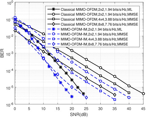
In Fig. 2, we compare the BER performance of the proposed MIMO-OFDM-IM scheme for N=4,K=2formulae-sequence𝑁4𝐾2N=4,K=2 with classical MIMO-OFDM for M=2𝑀2M=2 at same spectral efficiency values. As seen from Fig. 2, the proposed scheme provides significant BER performance improvement compared to classical MIMO-OFDM, which increases with higher order MIMO systems. As an example, the MIMO-OFDM-IM scheme achieves approximately 101010 dB better BER performance than classical MIMO-OFDM at a BER value of 105superscript10510^{-5} for the 8×8888\times 8 MIMO system.

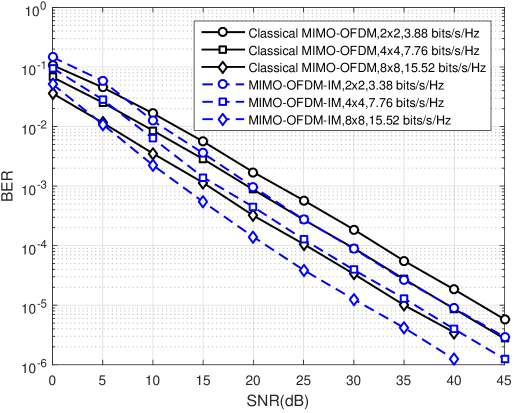
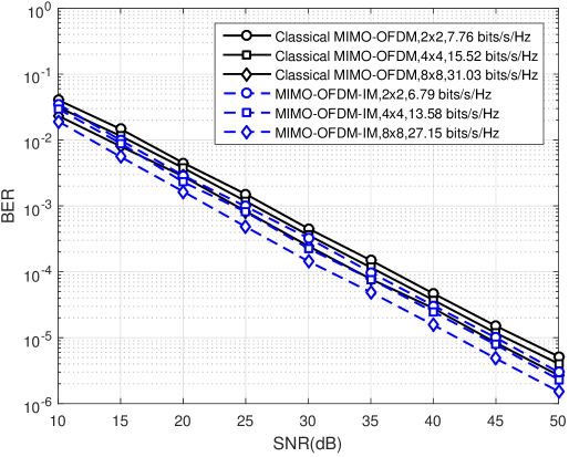
In Figs. 2 and 3, we extend our simulations to higher spectral efficiency values and compare the BER performance of the proposed MIMO-OFDM-IM scheme (N=4,K=3)formulae-sequence𝑁4𝐾3(N=4,K=3) with classical MIMO-OFDM for M=4𝑀4M=4 and 161616, respectively. As seen from Figs. 2 and 3, the proposed scheme still maintains its advantage over classical MIMO-OFDM in all considered configurations. It is interesting to note that the proposed scheme has the potential to achieve close or better BER performance than the reference scheme, even using a lower order MIMO system in most cases.

V Conclusions and Future Work

A novel scheme called MIMO-OFDM with index modulation has been proposed as an alternative multicarrier transmission technique for 5G networks. It has been shown via extensive computer simulations that the proposed scheme can provide significant BER performance improvements over classical MIMO-OFDM for several different configurations. The following points remain unsolved in this study: i) performance analysis, ii) the selection of optimal N𝑁N and K𝐾K values, iii) diversity techniques for MIMO-OFDM-IM, and iv) implementation scenarios for high mobility.

References

  • [1] J. Andrews, S. Buzzi, W. Choi, S. Hanly, A. Lozano, A. Soong, and J. Zhang, “What will 5G be?” IEEE J. Sel. Areas Commun., vol. 32, no. 6, pp. 1065–1082, Jun. 2014.
  • [2] E. Başar, Ü. Aygölü, E. Panayırcı, and H. V. Poor, “Orthogonal frequency division multiplexing with index modulation,” IEEE Trans. Signal Process., vol. 61, no. 22, pp. 5536–5549, Nov. 2013.
  • [3] R. Abu-alhiga and H. Haas, “Subcarrier-index modulation OFDM,” in Proc. IEEE Int. Sym. Personal, Indoor and Mobile Radio Commun., Tokyo, Japan, Sep. 2009, pp. 177–181.
  • [4] D. Tsonev, S. Sinanovic, and H. Haas, “Enhanced subcarrier index modulation (SIM) OFDM,” in Proc. IEEE GLOBECOM Workshops, Dec. 2011, pp. 728–732.
  • [5] Y. Ko, “A tight upper bound on bit error rate of joint OFDM and multi-carrier index keying,” IEEE Commun. Lett., vol. 18, no. 10, pp. 1763–1766, Oct. 2014.
  • [6] R. Fan, Y. Yu, and Y. Guan, “Generalization of orthogonal frequency division multiplexing with index modulation,” IEEE Trans. Wireless Commun., vol. PP, no. 99, pp. 1–10, May 2015.
  • [7] M. Wen, X. Cheng, and L. Yang, “Optimizing the energy efficiency of OFDM with index modulation,” in IEEE Int. Conf. Commun. Systems, Nov. 2014, pp. 31–35.
  • [8] W. Li, H. Zhao, C. Zhang, L. Zhao, and R. Wang, “Generalized selecting sub-carrier modulation scheme in OFDM system,” in IEEE Int. Conf. Commun. Workshops, Jun. 2014, pp. 907–911.
  • [9] E. Başar, “OFDM with index modulation using coordinate interleaving,” IEEE Wireless Commun. Lett., vol. PP, no. 99, pp. 1–4, Apr. 2015.
  • [10] Y. Xiao, S. Wang, L. Dan, X. Lei, P. Yang, and W. Xiang, “OFDM with interleaved subcarrier-index modulation,” IEEE Commun. Lett., vol. 18, no. 8, pp. 1447–1450, Aug. 2014.
  • [11] X. Cheng, M. Wen, L. Yang, and Y. Li, “Index modulated OFDM with interleaved grouping for V2X communications,” in IEEE Int. Conf. Intelligent Transportation Systems, Oct. 2014, pp. 1097–1104.
  • [12] W. Zhang, X.-G. Xia, and K. Ben Letaief, “Space-time/frequency coding for MIMO-OFDM in next generation broadband wireless systems,” IEEE Wireless Commun., vol. 14, no. 3, pp. 32–43, Jun. 2007.
  • [13] Y. Jiang, M. Varanasi, and J. Li, “Performance analysis of ZF and MMSE equalizers for MIMO systems: An in-depth study of the high SNR regime,” IEEE Trans. Inf. Theory, vol. 57, no. 4, pp. 2008–2026, Apr. 2011.
Refer to caption
Figure 2: Performance comparison of MIMO-OFDM and MIMO-OFDM-IM (N=4,K=2)formulae-sequence𝑁4𝐾2(N=4,K=2) for BPSK modulation (M=2)𝑀2(M=2), MMSE/ML detection
Refer to caption
Figure 3: Performance comparison of MIMO-OFDM and MIMO-OFDM-IM (N=4,K=3)formulae-sequence𝑁4𝐾3(N=4,K=3) for QPSK modulation (M=4)𝑀4(M=4), MMSE detection
Refer to caption
Figure 4: Performance comparison of MIMO-OFDM and MIMO-OFDM-IM (N=4,K=3)formulae-sequence𝑁4𝐾3(N=4,K=3) for 161616-QAM (M=16)𝑀16(M=16), MMSE detection