Giant enhancement of the third harmonic in graphene integrated in a layered structure
Abstract
Graphene was shown to have strongly nonlinear electrodynamic properties. In particular, being irradiated by an electromagnetic wave with the frequency , it can efficiently generate higher frequency harmonics. Here we predict that in a specially designed structure “graphene – dielectric – metal” the third-harmonic () intensity can be increased by more than two orders of magnitude as compared to an isolated graphene layer.
pacs:
78.67.Wj, 42.65.Ky, 73.50.FqIt was theoretically predicted Mikhailov (2007) that, due to the “ultra-relativistic”, massless energy dispersion of graphene electrons,
| (1) |
it should demonstrate a strongly nonlinear electrodynamic response; here cm/s is the Fermi velocity of graphene and is the electron wave-vector. Physically, this is due to the absence of inertia of graphene electrons: According to (1), electrons can move only with the velocity in any directions, therefore, being placed in the oscillating external electric field they have to “instantaneously” change their velocity from to in the return points. This leads to the emission of radiation at higher (multiple) frequencies as well as to other nonlinear phenomena. The efficiency of the nonlinear effects in graphene was predicted to be many orders of magnitude larger than in many other nonlinear materials Mikhailov (2007).
Experimentally, a strong nonlinearity of the graphene response has been confirmed at microwave Dragoman et al. (2010) and optical Hendry et al. (2010) frequencies. Further experimental studies of different nonlinear electrodynamic effects in graphene can be found in Refs. Dean and van Driel (2010); Wu et al. (2011); Zhang et al. (2012); Bykov et al. (2012); Kumar et al. (2013); Hong et al. (2013); An et al. (2014); Lin et al. (2014). A quasi-classical theory of the nonlinear electrodynamic response of graphene, which is valid at relatively low (microwave, terahertz) frequencies , has been developed in Refs. Mikhailov (2007); Mikhailov and Ziegler (2008); Mikhailov (2009, 2011, 2012); Smirnova et al. (2014); Yao et al. (2014); Peres et al. (2014); here is the Fermi energy. This theory takes into account only the intra-band electronic transitions and ignores the inter-band ones. More general, quantum theories, which take into account both contributions, have been recently proposed in Refs. Cheng et al. (2014a); Mikhailov (2014); Cheng et al. (2014b, 2015); Mikhailov (2015); Semnani et al. (2015). It was shown that, apart from a strong resonance at low () frequencies, the third-order nonlinear conductivity demonstrates a number of resonances at the frequencies corresponding to the one-, two- and three-photon inter-band absorption.
In Refs. Cheng et al. (2014a); Mikhailov (2014); Cheng et al. (2014b, 2015); Mikhailov (2015); Semnani et al. (2015) the third-order nonlinear response functions of graphene have been calculated for a single, freely hanging in vacuum (or in air) mono-atomic graphene layer. In reality graphene lies of a dielectric substrate (of thickness ). In this Letter we study the influence of the dielectric environment on the efficiency of the third harmonic generation and show that, depending on the ratio , as well as on physical properties of layers supporting graphene, the output third harmonic intensity can be both several orders of magnitude smaller and several orders of magnitude larger than in the isolated graphene layer. A proper choice of the geometrical parameters and physical properties of the dielectric environment is thus vitally important for the successful operation of graphene based nonlinear devices.
As an example, we consider a layered system “graphene – medium 1 – medium 2” where a two-dimensional graphene layer lies at the plane and each of the media is characterized by a thickness and a complex dielectric permittivity , . We assume that a linearly polarized (in the -direction) electromagnetic wave with the frequency and the power density is normally incident on the structure from the graphene side, see insets to Figs. 1 and 3(b). The distribution of electromagnetic fields in the system is described by Maxwell equations with the dielectric function , being equal to inside the -th layer, and with the term , describing the current in the two-dimensional graphene layer. The current in graphene has the linear and the third-harmonic components, and , where is the Fourier component of the self-consistent electric field at the plane , and and are the first- and third-order conductivities of an isolated graphene layer.
We solve the outlined nonlinear electrodynamic problem in two steps. First, we calculate, within the first-order response theory, Refs. Falkovsky and Varlamov (2007); Gusynin et al. (2007); Mikhailov and Ziegler (2007), the Fourier components of the electric field and current, and relate the amplitude of the ac electric field at the plane to the amplitude of the incident wave . Then we substitute the third-order current in Maxwell equations and calculate the amplitudes of the Fourier components of the waves emitted in the forward and backward directions. We neglect the influence of the nonlinear effects on the amplitudes of ; these effects, determined by , give small corrections to our results. Having found the amplitudes of the components of the electric and magnetic fields, we calculate the intensity of the third harmonic, as a function of the input-wave frequency and the thicknesses and material parameters of the media 1 and 2, and compare it with the third-harmonic intensity emitted by the isolated graphene layer.
Figures 1 – 3 show our results. We assume that the graphene layer has the electron density cm-2 and the effective scattering time ps. The medium 1 is assumed to be a dielectric with the frequency independent refractive index (a reasonable assumption if is much smaller than the band gap in the dielectric). The medium 2 (if present) is assumed to be a metal (gold) with the complex dielectric function described by the Drude model with the plasma frequency eV and the scattering time fs. These numbers are taken from Ref. Olmon et al. (2012) where it was shown that the Drude model gives a good description of the dielectric properties of gold at the photon energies lower than eV. In Figures 2 – 3 we assume that the wavelength of the incident wave is m (the frequency THz, eV).
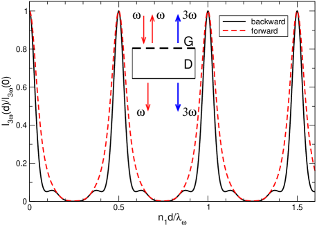
Figure 1 shows the third harmonic intensity emitted from graphene lying on the dielectric substrate with the thickness , as a function of the dimensionless dielectric thickness . The intensity strongly oscillates as a function of , with maxima corresponding to the integer () numbers of half-wavelengths () inside the dielectric slab,
| (2) |
under these conditions the field at is maximal. In the maxima the values of are the same as in the isolated graphene , but in the minima they can be several orders of magnitude smaller [ in Fig. 1; here is the third-harmonic intensity emitted only in one, forward or backward, direction]. A proper choice of the dielectric thickness is thus of extreme importance for observation of the third harmonic generation. In Fig. 1 one also sees a difference in the intensity of the -waves emitted in the forward and backward directions: the intensity of the backward radiation is smaller and has additional resonances corresponding to the interference condition for the third harmonic, , .
Now consider the case when a thin metallic (Au) layer with the thickness covers the backside of the dielectric substrate. In this case the third harmonic intensity strongly depends on whether the -wave is emitted in the forward (transmission) or in the backward (reflection) direction. Figure 2 shows the normalized intensity of the third harmonic, emitted by the structure in the forward direction, as a function of the dielectric thickness at several different metal thicknesses .
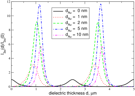
A few interesting features are seen in Fig. 2. First, when the metal thickness increases from nm (the black solid curve; corresponds to the red dashed curve in Fig. 1) up to nm, the maxima of tend to new positions determined by the relation
| (3) |
and the intensity of the transmitted third-harmonic signal substantially (by more than one order of magnitude) increases. The quarter-wavelength shift in (3), as compared to (2), results from the boundary condition for the tangential electric field at the metallic plane , . This also leads to a larger fundamental-frequency electric field at the graphene plane , and hence, to a larger third-harmonic signal.
When grows further, the intensity reaches its maximum and then decreases (at nm), since at large the metallic layer becomes opaque both for the fundamental () and for the third () harmonic.
Figure 3 shows the intensity of the third harmonic emitted in the backward direction. One sees that the maxima of the curves also move to the -values (3) when increases. However, in contrast to the forward-direction emission, in these -points monotonously grows with and saturates at nm, reaching the value . If to take into account that the total third-harmonic intensity emitted by an isolated graphene layer in both (forward and backward) directions equals , one sees that just the metalization of the backside of the substrate may increase the total emitted power by more than two orders of magnitude (by the factor of ).
Such a giant enhancement of the third harmonic intensity is explained by the interference of both the incident wave () and its third harmonic () in the dielectric slab. Indeed, in the case of a single (isolated) graphene layer in air the third order current in the layer is of order , where is the amplitude of the incident wave (in this simple estimate we ignore the difference between and ). The electric and magnetic fields of the emitted third harmonic are proportional to , , and the intensity of the emitted radiation (in one direction) is proportional to . The total emitted power (both in the backward and forward directions) is then .
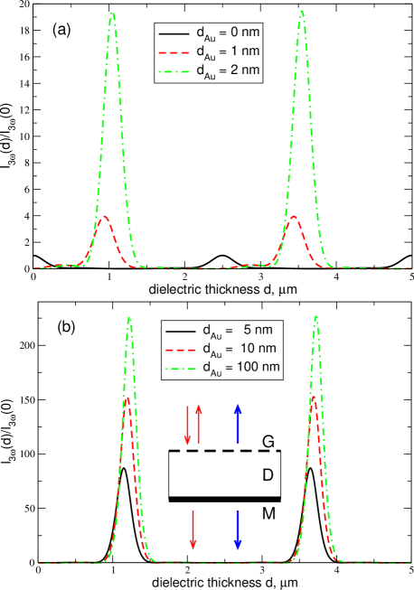
If the graphene layer lies on the dielectric slab metalized on the back side, the fundamental-frequency electric field at the plane is twice as large (in the interference maximum) as the incident wave field, , due to the reflection of the wave from the back-side mirror. The third-order current is then . The fields , of the excited third-harmonic wave, emitted from the graphene plane in both directions, are proportional to the current , but since the -wave is reflected from the mirror again, they should be multiplied by two once more, . The total emitted power (only in the backward direction) is then proportional to . Comparing with we see that the amplification factor, due to the substrate with a metalized back side, is about . The slightly smaller factor obtained in the more accurate theory above (Fig. 3) is due to the small difference between and which we have neglected.
Our results thus show that, placing graphene on the surface of a dielectric slab with a metalized back side one can increase the generated third-harmonic intensity by more than two orders of magnitude (a further enhancement of the third harmonic can be achieved by placing graphene inside a Fabry-Pérot-type cavity with a high quality factor). Parameters of such a graphene-based frequency multiplier should however be carefully chosen since the dielectric thickness and the input radiation frequency (or the wavelength ) should be related by the resonant conditions (3). As seen from Figs. 1 – 3, deviations from these relations may suppress the output signal by orders of magnitude. In addition, a further (resonant) enhancement of the third harmonic at infrared frequencies can be achieved by tuning the density of electrons in graphene, since the positions of the inter-band resonances depend on the Fermi energy.
It should be noticed that numerical values of the third-order parameters of graphene, experimentally measured in different papers, quite substantially differ from each other, see, e.g., a discussion in Cheng et al. (2014a). This may be due to a better or worse fulfillment of the resonant conditions (2) or (3) in different experiments. It can also be noticed that another way to increase the third harmonic generation (by a factor of ) was proposed in Ref. Smirnova and Solntsev (2015). In that paper the radiation propagates along the layered structure, containing graphene, the low-frequency regime is considered () and the third-harmonic enhancement is achieved by utilizing cascaded processes. A Fabry-Pérot cavity with a graphene layer inside was proposed to be used for the enhancement of the linear absorption in intrinsic () graphene in Ref. Ferreira et al. (2012).
To summarize, we have studied the third-harmonic generation effect in the structure graphene–dielectric–metal and found the optimal operation conditions of such a frequency multiplier, Eq. (3). Properly choosing the system parameters one can get a giant, resonant enhancement of the up-conversion efficiency. Conversely, under the off-resonant conditions the device efficiency is suppressed by many orders of magnitude. The correct choice of the device parameters, Eq. (3), is thus of particular importance for its proper operation.
The work was supported by the European Union under the Program Graphene Flagship (No. CNECT-ICT-604391).
References
- Mikhailov (2007) S. A. Mikhailov, Europhys. Lett. 79, 27002 (2007).
- Dragoman et al. (2010) M. Dragoman, D. Neculoiu, G. Deligeorgis, G. Konstantinidis, D. Dragoman, A. Cismaru, A. A. Muller, and R. Plana, Appl. Phys. Lett. 97, 093101 (2010).
- Hendry et al. (2010) E. Hendry, P. J. Hale, J. J. Moger, A. K. Savchenko, and S. A. Mikhailov, Phys. Rev. Lett. 105, 097401 (2010).
- Dean and van Driel (2010) J. J. Dean and H. M. van Driel, Phys. Rev. B 82, 125411 (2010).
- Wu et al. (2011) R. Wu, Y. Zhang, S. Yan, F. Bian, W. Wang, X. Bai, X. Lu, J. Zhao, and E. Wang, Nano Lett. 11, 5159-5164 (2011).
- Zhang et al. (2012) H. Zhang, S. Virally, Q. Bao, L. K. Ping, S. Massar, N. Godbout, and P. Kockaert, Optics Letters 37, 1856 (2012).
- Bykov et al. (2012) A. Y. Bykov, T. V. Murzina, M. G. Rybin, and E. D. Obraztsova, Phys. Rev. B 85, 121413(R) (2012).
- Kumar et al. (2013) N. Kumar, J. Kumar, C. Gerstenkorn, R. Wang, H.-Y. Chiu, A. L. Smirl, and H. Zhao, Phys. Rev. B 87, 121406(R) (2013).
- Hong et al. (2013) S.-Y. Hong, J. I. Dadap, N. Petrone, P.-C. Yeh, J. Hone, and R. M. Osgood, Jr., Phys. Rev. X 3, 021014 (2013).
- An et al. (2014) Y. Q. An, J. E. Rowe, D. B. Dougherty, J. U. Lee, and A. C. Diebold, Phys. Rev. B 89, 115310 (2014).
- Lin et al. (2014) K.-H. Lin, S.-W. Weng, P.-W. Lyu, T.-R. Tsai, and W.-B. Su, Appl. Phys. Lett. 76, 151605 (2014).
- Mikhailov and Ziegler (2008) S. A. Mikhailov and K. Ziegler, J. Phys. Condens. Matter 20, 384204 (2008).
- Mikhailov (2009) S. A. Mikhailov, Microelectron. J. 40, 712 (2009).
- Mikhailov (2011) S. A. Mikhailov, in Physics and Applications of Graphene: Theory, edited by S. A. Mikhailov (InTech, Rijeka, Croatia, 2011) Chap. 25, pp. 519–534.
- Mikhailov (2012) S. A. Mikhailov, Physica E 44, 924 (2012).
- Smirnova et al. (2014) D. A. Smirnova, I. V. Shadrivov, A. E. Miroshnichenko, A. I. Smirnov, and Y. S. Kivshar, Phys. Rev. B 90, 035412 (2014).
- Yao et al. (2014) X. Yao, M. Tokman, and A. Belyanin, Phys. Rev. Lett. 112, 055501 (2014).
- Peres et al. (2014) N. M. R. Peres, Y. V. Bludov, J. E. Santos, A.-P. Jauho, and M. I. Vasilevskiy, Phys. Rev. B 90, 125425 (2014).
- Cheng et al. (2014a) J. L. Cheng, N. Vermeulen, and J. E. Sipe, New J. Phys. 16, 053014 (2014a).
- Mikhailov (2014) S. A. Mikhailov, Phys. Rev. B 90, 241301(R) (2014), Phys. Rev. B, 91, 039904(E) (2015).
- Cheng et al. (2014b) J. L. Cheng, N. Vermeulen, and J. E. Sipe, Optics Express 22, 15868 (2014b).
- Cheng et al. (2015) J. L. Cheng, N. Vermeulen, and J. E. Sipe, Phys. Rev. B 91, 235320 (2015).
- Mikhailov (2015) S. A. Mikhailov, “Quantum theory of the third-order nonlinear electrodynamic effects in graphene,” (2015), arXiv:1506.00534.
- Semnani et al. (2015) B. Semnani, A. H. Majedi, and S. Safavi-Naeini, “Nonlinear quantum optical properties of graphene: the role of chirality and symmetry,” (2015), arXiv:1502.02203.
- Falkovsky and Varlamov (2007) L. A. Falkovsky and A. A. Varlamov, Europ. Phys. J. B 56, 281 (2007).
- Gusynin et al. (2007) V. P. Gusynin, S. G. Sharapov, and J. P. Carbotte, Phys. Rev. Lett. 98, 157402 (2007).
- Mikhailov and Ziegler (2007) S. A. Mikhailov and K. Ziegler, Phys. Rev. Lett. 99, 016803 (2007).
- Olmon et al. (2012) R. L. Olmon, B. Slovick, T. W. Johnson, D. Shelton, S.-H. Oh, G. D. Boreman, and M. B. Raschke, Phys. Rev. B 86, 235147 (2012).
- Smirnova and Solntsev (2015) D. A. Smirnova and A. S. Solntsev, “Cascaded third harmonic generation in hybrid graphene-semiconductor waveguides,” (2015), arXiv:1507.01361.
- Ferreira et al. (2012) A. Ferreira, N. M. R. Peres, R. M. Ribeiro, and T. Stauber, Phys. Rev. B 85, 115438 (2012).