Atom Interferometer Gyroscope with Spin-Dependent Phase Shifts Induced by Light near a Tune-out Wavelength
Abstract
Tune-out wavelengths measured with an atom interferometer are sensitive to laboratory rotation rates because of the Sagnac effect, vector polarizability, and dispersion compensation. We observed shifts in measured tune-out wavelengths as large as 213 pm with a potassium atom beam interferometer, and we explore how these shifts can be used for an atom interferometer gyroscope.
Atom interferometers have an impressive variety of applications ranging from inertial sensing to measurements of fundamental constants, measurements of atomic properties, and studies of topological phases Cronin et al. (2009). In particular, making a better gyroscope has been a long standing goal in the atom optics community because atom interferometers have the potential to outperform optical Sagnac gyroscopes. Advances in the precision and range of applications for atom interferometry have been realized by using interferometers with multiple atomic species Varoquaux et al. (2009); Bonnin et al. (2013); Berninger et al. (2007); Holmgren et al. (2010), multiple atomic velocities Gustavson et al. (2000); Durfee et al. (2006); Canuel et al. (2006); Dickerson et al. (2013); Hammond et al. (1995), multiple atomic spin states Schmiedmayer et al. (1994); Petrovic et al. (2013); Lombardi et al. (2014), and multiple atomic path configurations Geiger et al. (2011); Robert-De-Saint-Vincent et al. (2010); Li et al. (2014); Gupta et al. (2002); Aoki et al. (2001). Here, we use atoms with multiple spin states to demonstrate a new method for rotation sensing. Our atom interferometer gyroscope reports the absolute rotation rate in terms of an optical wavelength, using a spin-dependent phase echo induced by light near a tune-out wavelength.
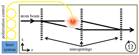
A tune-out wavelength, , occurs where the dynamic polarizability of an atom changes sign between two resonances Arora et al. (2011); LeBlanc and Thywissen (2007); Herold et al. (2012); Cheng et al. (2013); Mitroy and Tang (2013); Topcu and Derevianko (2013); Jiang and Mitroy (2013); Jiang et al. (2013); Safronova et al. (2013, 2012); Holmgren et al. (2012). Since atomic vector polarizability depends on spin Manakov et al. (1986); Rosenbusch et al. (2009); Le Kien et al. (2013), theoretical tune-out wavelengths usually describe atoms with spin . The same should be found, on average, for atoms in a uniform distribution of spin states. However, in this Letter, we show that the Sagnac effect breaks the symmetry expected from the vector polarizability in a way that makes tune-out wavelengths remarkably sensitive to the laboratory rotation rate. We measured tune-out wavelengths using a potassium atom interferometer shown in Fig. 1 and circularly polarized light, and found that our measurements were shifted by 0.213 nm from the theoretical tune-out wavelength of nm Arora et al. (2011). This shift is more than 100 times larger than the uncertainty with which can be measured Holmgren et al. (2012), and this suggests the possibility of creating a sensitive gyroscope using tune-out wavelengths. The purpose of this Letter is therefore to explain how an atom interferometer gyroscope can measure the laboratory rotation rate with the aid of atomic spin-dependent phase shifts induced by light near a tune-out wavelength. This is a new application of tune-out wavelengths and a new method for atom interferometry that could improve sensors needed for navigation, geophysics, and tests of general relativity.
Atom interferometer gyroscopes Lenef et al. (1997); Gustavson et al. (2000, 1997); Durfee et al. (2006); Canuel et al. (2006); Lan et al. (2012); Dickerson et al. (2013); Müller et al. (2009); Wu et al. (2007); Stockton et al. (2011); Cronin et al. (2009); Barrett et al. (2014) can sense changes in rotation rate () because of the Sagnac effect. Some atom interferometers Gustavson et al. (1997); Durfee et al. (2006); Canuel et al. (2006); Lan et al. (2012); Dickerson et al. (2013) can also report the absolute rotation rate () with respect to an inertial frame of reference since the Sagnac phase depends on atomic velocity. Because the Sagnac phase is dispersive, can affect the interference fringe contrast. References Gustavson et al. (1997, 2000); Durfee et al. (2006); Canuel et al. (2006); Lan et al. (2012); Dickerson et al. (2013) applied auxiliary rotations to an atom interferometer to compensate for the earth’s rotation and thus maximize contrast. References Gustavson et al. (1997) and Lan et al. (2012) even used contrast as a function of applied rotation rate in order to measure .
In comparison, here we demonstrate optical and static electric field gradients that compensate for dispersion in the Sagnac phase. This is a general example of dispersion compensation Roberts et al. (2004); Jacquey et al. (2008) in which one type of phase compensates for dispersion in another. Furthermore, we show that circularly polarized light at makes an observable -dependent phase shift for our unpolarized atom beam interferometer. This works because spin-dependent dispersion compensation causes higher contrast for one spin state. Thus, using spin as a degree of freedom and light near a tune-out wavelength, we made a gyroscope that reports the absolute rotation rate in terms of a light-induced phase shift.
Our gyroscope uses material nanogratings which permit interferometry with distributions of atomic spin and velocity, both of which are needed in order to cause the shifts in that are sensitive to . An atom interferometer like ours was previously shown to monitor changes in rotation rate Lenef et al. (1997). We now show that an atom interferometer gyroscope with material nanogratings can measure absolute rotation rates smaller than . This is significant because nanogratings offer some advantages such as simplicity, reliability, and spin-independent and nearly velocity-independent diffraction amplitudes that may enable more robust and economical sensors.
We studied the light-induced phase shift for an ensemble of atoms, which we model as
| (1) |
where is the measured phase when the light is on and is the measured phase when the light is off. For an atom beam with a velocity distribution and a uniform distribution of spin states , the contrast and phase for the ensemble are described by
| (2) |
where . Here, is the velocity-dependent and spin-dependent phase caused by light, is the velocity-dependent Sagnac phase, is the velocity-dependent phase induced by an acceleration or gravity, is the initial phase, and is the initial contrast of the interferometer. A similar equation can be written for with the light off, so that . Our atom beam has a velocity distribution adequately described by , where is a normalization constant Haberland et al. (1985).
The Sagnac phase Lenef et al. (1997); Gustavson et al. (1997)
| (3) |
is a function of atomic velocity and the rotation rate along the normal of the interferometer’s enclosed area. is the distance between gratings and is the period of the gratings. In our interferometer, nm and m, so radians for a 1600 m/s atom beam in our laboratory at N latitude due to .
The gravity phase Lenef et al. (1997) is
| (4) |
where is the gravitational acceleration along the grating wave vector direction. As we discuss later, and are small, but non-zero.
The light phase is
| (5) |
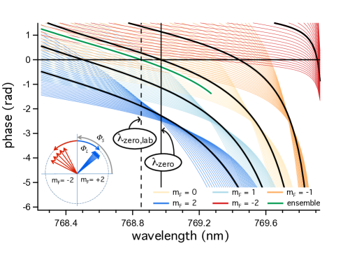
where the dynamic polarizability depends on the atomic state and the laser polarization Manakov et al. (1986); Rosenbusch et al. (2009); Le Kien et al. (2013). Near the second nanograting, we shine 50 mW of laser light perpendicular to the plane of the interferometer. The laser’s irradiance gradient in a beam with a 100 m diameter waist asymmetrically illuminates the atom beam paths as sketched in Fig. 1. The irradiance gradient is integrated along the atom beam paths in the -direction. The path separation is proportional to . Hence, for laser beams much wider than , the light phase approximately depends on . The fact that this does not exactly match the dispersion of the Sagnac phase means the dispersion compensation is imperfect, which is why we see caustics in Fig. 2. Figure 2 presents modeled phase shifts for ground state potassium atoms with several different velocities and five different spin states. Figure 2 illustrates how spin-dependent dispersion compensation works, and how it can make .
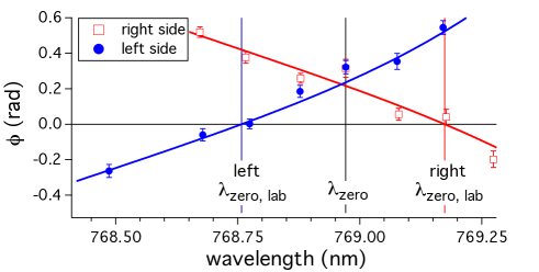
The way affects the light-induced phase leads to several testable predictions that we experimentally verified. Equation (2) led us to predict a new wavelength for which is zero. A simulation of this prediction is shown in Fig. 2, and data demonstrating +203 to -213 pm shifts in are shown in Fig. 3.
Higher irradiance on the left interferometer path when looking from the source towards the detector would cause a longer (if the grating tilt were zero, so that ). This is because attraction towards light on the left compensates for in the northern hemisphere, and only spin states with roots in at longer wavelengths are attracted to light at . These states therefore contribute with more weight to because of dispersion compensation. On the other side, if the irradiance is stronger on the right-hand interferometer path, then repulsion from the light compensates for , and spin states with roots in at shorter wavelengths contribute more to . Grating tilt and the gravity phase complicate this picture. In our experiment, the dispersion is opposite and slightly larger in magnitude than the dispersion , so higher irradiance on the left path of the atom interferometer causes a shorter . Figure 3 shows data verifying this prediction.
We predict that the wavelength difference will not change if the optical -vector reverses direction, nor if the optical circular polarization reverses handedness, nor if the magnetic field parallel to the optical -vector reverses direction. None of these reversals change the fact that a potential gradient that is attractive towards the left side (or repulsive from the right side) is needed to compensate for the Sagnac phase dispersion in the northern hemisphere. Therefore, the magnitude can increase if the laser is simply reflected over the atom beam path. We tested this prediction by constructing an optical cavity with plane mirrors to recycle light so that the same interferometer path is exposed to upward and downward propagating laser beams for several passes. This increased the magnitude of as predicted.
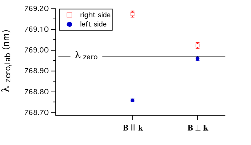
External magnetic fields also affect . A uniform magnetic field parallel or anti-parallel to the optical -vector maximizes the sensitivity to optical polarization. Alternatively, a magnetic field perpendicular to the optical -vector reduces because the atomic spin states precess about the field so the resulting spin-dependent differences in light shift time-average to zero. Data in Fig. 4 show that is closer to when we apply a perpendicular magnetic field. Residual differences between and are due to imperfect alignment of the magnetic field perpendicular to the -vector and the limited (15 G) strength of the magnetic field.
Based on the work presented thus far, deducing from measurements of is challenging because it requires knowing the magnetic field, the laser power, laser polarization, laser beam waist, and the atom beam velocity spread. To solve this problem, we used a static electric field gradient to induce additional phase shifts that mimic the effect of auxiliary rotation on the atom interferometer (to first order in ). A measurement of light-induced phase shift as a function of electric-field induced phase shift can serve to calibrate the relationship between and . Furthermore, we can determine the absolute rotation rate of the laboratory by measuring the additional phase shift needed to make . The phase due to a static electric field gradient is
| (6) |
where is the static electric dipole polarizability Holmgren et al. (2010). The observed phase shift for the ensemble of atoms due to an electric field gradient, , is calculated using Eq. (2) with added to (and ). This phase shift can compensate for the dispersion in the Sagnac phase uniformly for all atomic spin states.
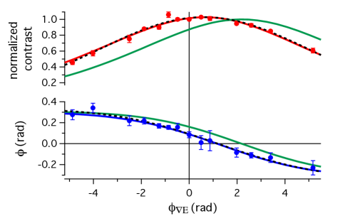
In Fig. 5, we show that depends continuously on , just as would on . Specifically, is the phase shift caused by light at . The data in Fig. 5 are obtained by alternately turning on and off, blocking and unblocking the laser, and then repeating the process with a new strength. Importantly, the root in phase at occurs when the electric field gradient compensates for dispersion in and . We can interpret this condition mathematically as
| (7) |
and then it becomes unnecessary to know the laser power or to perform the integral over velocity shown in Eq. (2) for reporting . Using the approximation we find
| (8) |
Equation (8) does not include because when Eq. (7) is satisfied there is no net dispersion to break the symmetry; so including in Eq. (2) produces zero ensemble phase shift . The fact that Eq. (8) does not include is convenient because now we can use light at to measure without precise knowledge of the laser spot size, polarization or irradiance, or the resultant slope . Those factors affect the precision with which we can find the root (), but not the value of the root. We also emphasize that an electric field gradient can be used to increase the dynamic range of our gyroscope.
To report , we measured rad with data in Fig. 5, we measured m/s using phase choppers Holmgren et al. (2011), and we measured mrad by comparing the nanograting bars to a plumb line. We find , which can be compared to the expected value 0.5 (the vertical projection of at our latitude of 32∘ N). In Fig. 5, we also show how depends on . The phase that maximizes contrast is another way to find the static electric field gradient that compensates for dispersion in the Sagnac phase and acceleration phase. The value of = 0.6(2) rad leads to . The dominant source of error in our experiment was the measurement of the nanograting tilt. Discrepancy between and indicates a systematic error, possibly caused by de Broglie wave phase front curvature induced by the laser beam Hromada et al. (2014), optical pumping, magnetic field gradients, or the broad band component of our laser spectrum.
The shot noise limited sensitivity of our atom interferometer gyroscope can be estimated from the fact that changes by 0.22 radians due to 0.53 , and the statistical phase noise is is 0.06 radians/ for our experimental values of , and = (100,000 counts/sec). This indicates a sensitivity of for measurements of rotation with respect to an inertial reference frame, which is competitive with methods presented in Gustavson et al. (1997); Dickerson et al. (2013); Durfee et al. (2006); Canuel et al. (2006); Lan et al. (2012).
To make a more sensitive gyroscope the scale factor can be somewhat increased by using more laser power and a broader velocity distribution. However, a limit to the sensitivity arises from balancing the benefit of an increased scale factor against the cost of increased statistical phase noise. This compromise occurs because maximizing the scale factor, , requires significant contrast loss from the two mechanisms described by Eq. (2): first, averaging over the spread in (which is affected by ) and second, averaging over the distribution in (which is affected by the laser power and polarization). Optimizing and laser power can increase the sensitivity (for the same flux and contrast) to for measurements.
This work also indicates how to make measurements of more independent of . Experiments are less sensitive to if they use linearly polarized light, a narrow velocity distribution, a perpendicular magnetic field, and an additional dispersive phase such as to compensate for . For example, the measurements in reference Holmgren et al. (2012) were not significantly affected by because there was minimal contrast loss at . Specifically, the sharp velocity distribution () made dispersion in reduce by less than 1%, and only reduced by 4% of so shifts in were less than 1 pm in Holmgren et al. (2012). To increase sensitivity to for measurements reported here, in Figs. 3 - 5, we used a broad velocity distribution () so reduced by 8%, and we also used a large irradiance gradient with circular polarization that reduced by 40% of .
In summary, an atom beam interferometer with multiple atomic spin states enabled us to demonstrate systematic shifts in tune-out wavelength measurements () that are larger than 200 pm due to rotation and acceleration. Then, we used the phase induced by light at a theoretical tune-out wavelength as a function of an additional dispersive phase applied to report the rotation rate of the laboratory with an uncertainty of 0.2 . This work is a new application for tune-out wavelengths, paves the way for improving precision measurements of tune-out wavelengths, and demonstrates a new technique for atom interferometer gyroscopes. The spin-multiplexing techniques demonstrated here may find uses in other atom Petrovic et al. (2013); Lombardi et al. (2014) and neutron Hasegawa and Rauch (2011); de Haan et al. (2014) interferometry experiments, and also in NMR gyroscopes and NMR spectroscopy.
This work is supported by NSF Grant No. 1306308 and a NIST PMG. R.T. and M.D.G. also thank NSF GRFP Grant No. DGE-1143953 for support. We also thank Professor Brian P. Anderson for helpful discussions.
References
- Cronin et al. (2009) A. D. Cronin, J. Schmiedmayer, and D. E. Pritchard, Rev. Mod. Phys. 81, 1051 (2009).
- Varoquaux et al. (2009) G. Varoquaux et al., N. J. Phys. 11, 113010 (2009).
- Bonnin et al. (2013) A. Bonnin, N. Zahzam, Y. Bidel, and A. Bresson, Phys. Rev. A 88, 043615 (2013).
- Berninger et al. (2007) M. Berninger, A. Stefanov, S. Deachapunya, and M. Arndt, Phys. Rev. A 76, 013607 (2007).
- Holmgren et al. (2010) W. F. Holmgren, M. C. Revelle, V. P. A. Lonij, and A. D. Cronin, Phys. Rev. A 81, 053607 (2010).
- Gustavson et al. (2000) T. L. Gustavson, A. Landragin, and M. A. Kasevich, Class. Quant. Grav. 17, 2385 (2000).
- Durfee et al. (2006) D. S. Durfee, Y. K. Shaham, and M. A. Kasevich, Phys. Rev. Lett. 97, 240801 (2006).
- Canuel et al. (2006) B. Canuel et al., Phys. Rev. Lett. 97, 010402 (2006).
- Dickerson et al. (2013) S. M. Dickerson, J. M. Hogan, A. Sugarbaker, D. M. S. Johnson, and M. A. Kasevich, Phys. Rev. Lett. 111, 083001 (2013).
- Hammond et al. (1995) T. Hammond, D. Pritchard, M. Chapman, A. Lenef, and J. Schmiedmayer, App. Phys. B 60, 193 (1995).
- Schmiedmayer et al. (1994) J. Schmiedmayer, C. R. Ekstrom, M. S. Chapman, T. D. Hammond, and D. E. Pritchard, Journal de Physique II 4, 2029 (1994).
- Petrovic et al. (2013) J. Petrovic, I. Herrera, P. Lombardi, F. Schaefer, and F. S. Cataliotti, N. J. Phys. Physics 15, 043002 (2013).
- Lombardi et al. (2014) P. Lombardi et al., Optics Express 22, 19141 (2014).
- Geiger et al. (2011) R. Geiger et al., Nat. Commun. 2, 474 (2011).
- Robert-De-Saint-Vincent et al. (2010) M. Robert-De-Saint-Vincent et al., Eur. Phys. Lett. 89, 10002 (2010).
- Li et al. (2014) W. Li, T. He, and A. Smerzi, Phys. Rev. Lett. 113, 023003 (2014).
- Gupta et al. (2002) S. Gupta, K. Dieckmann, Z. Hadzibabic, and D. E. Pritchard, Phys. Rev. Lett. 89, 140401 (2002).
- Aoki et al. (2001) T. Aoki, K. Shinohara, and A. Morinaga, Phys. Rev. A 63, 063611 (2001).
- Arora et al. (2011) B. Arora, M. S. Safronova, and C. W. Clark, Phys. Rev. A 84, 043401 (2011).
- LeBlanc and Thywissen (2007) L. J. LeBlanc and J. H. Thywissen, Phys. Rev. A 75, 053612 (2007).
- Herold et al. (2012) C. D. Herold et al., Phys. Rev. Lett. 109, 243003 (2012).
- Cheng et al. (2013) Y. Cheng, J. Jiang, and J. Mitroy, Phys. Rev. A 88, 022511 (2013).
- Mitroy and Tang (2013) J. Mitroy and L.-Y. Tang, Phys. Rev. A 88, 052515 (2013).
- Topcu and Derevianko (2013) T. Topcu and A. Derevianko, Phys. Rev. A 88, 053406 (2013).
- Jiang and Mitroy (2013) J. Jiang and J. Mitroy, Phys. Rev. A 88, 032505 (2013).
- Jiang et al. (2013) J. Jiang, L.-Y. Tang, and J. Mitroy, Phys. Rev. A 87, 032518 (2013).
- Safronova et al. (2013) M. S. Safronova, U. I. Safronova, and C. W. Clark, Phys. Rev. A 87, 052504 (2013).
- Safronova et al. (2012) M. S. Safronova, U. I. Safronova, and C. W. Clark, Phys. Rev. A 86, 042505 (2012).
- Holmgren et al. (2012) W. F. Holmgren, R. Trubko, I. Hromada, and A. D. Cronin, Phys. Rev. Lett. 109, 243004 (2012).
- Manakov et al. (1986) N. L. Manakov, V. Ovsiannikov, and L. Rapoport, Physics Reports 141, 320 (1986).
- Rosenbusch et al. (2009) P. Rosenbusch et al., Phys. Rev. A 79, 013404 (2009).
- Le Kien et al. (2013) F. Le Kien, P. Schneeweiss, and A. Rauschenbeutel, Eur. Phys. J. D 67, 1 (2013).
- Lenef et al. (1997) A. Lenef et al., Phys. Rev. Lett. 78, 760 (1997).
- Gustavson et al. (1997) T. L. Gustavson, P. Bouyer, and M. A. Kasevich, Phys. Rev. Lett. 78, 2046 (1997).
- Lan et al. (2012) S.-Y. Lan, P.-C. Kuan, B. Estey, P. Haslinger, and H. Müller, Phys. Rev. Lett. 108, 090402 (2012).
- Müller et al. (2009) T. Müller et al., Eur. Phys. J. D 53, 273 (2009).
- Wu et al. (2007) S. Wu, E. Su, and M. Prentiss, Phys. Rev. Lett. 99, 173201 (2007).
- Stockton et al. (2011) J. K. Stockton, K. Takase, and M. A. Kasevich, Phys. Rev. Lett. 107, 133001 (2011).
- Barrett et al. (2014) B. Barrett et al., Comptes Rendus Physique 15, 875 (2014).
- Roberts et al. (2004) T. D. Roberts, A. D. Cronin, M. V. Tiberg, and D. E. Pritchard, Phys. Rev. Lett. 92, 060405 (2004).
- Jacquey et al. (2008) M. Jacquey, A. Miffre, G. Trénec, M. Büchner, J. Vigué, and A. Cronin, Phys. Rev. A 78, 013638 (2008).
- Haberland et al. (1985) H. Haberland, U. Buck, and M. Tolle, Rev. Sci. Instrum. 56, 1712 (1985).
- Holmgren et al. (2011) W. F. Holmgren, I. Hromada, C. E. Klauss, and A. D. Cronin, N. J. Phys. 13, 115007 (2011).
- Hromada et al. (2014) I. Hromada, R. Trubko, W. F. Holmgren, M. D. Gregoire, and A. D. Cronin, Phys. Rev. A 89, 033612 (2014).
- Hasegawa and Rauch (2011) Y. Hasegawa and H. Rauch, N. J. Phys. 13, 115010 (2011).
- de Haan et al. (2014) V. de Haan, Plomp, et al., Phys. Rev. A 89, 063611 (2014).