Ferromagnetic instability of interlayer floating electrons in quasi-two-dimensional electride Y2C
Abstract
Ab initio electronic structure calculations show that the recently identified quasi-two-dimensional electride Y2C is a weak itinerant ferromagnet or at least close to a ferromagnetic instability. The ferromagnetism is induced by the electride electrons, which are loosely bound around interstitial sites and overlap with each other to form two-dimensional interlayer conduction bands. The semimetallicity and two-dimensionality of the band structure are the key to understanding this ferromagnetic instability.
Introduction: Electrides are unconventional ionic materials in which there is an intrinsic excess of valence electrons from the formal valence viewpoint. Dy1 ; Dy2 ; Pi ; Pic ; Ki ; Mat The excess electrons float in the void space between ions and, if their energy band crosses the Fermi level, dominate the transport and magnetic properties. Electrides can be conveniently classified by the dimensionality of the electronic structure of the floating electrons. In zero-dimensional (0D) electrides, the floating electrons are localized at interstitial sites and form a narrow band, whereas 1D and 2D electrides have electrons floating inside filamentary channels and interlayer gaps, respectively. For decades, all the known electrides were either 0D or 1D, but recently Lee et al. Le have demonstrated, through transport measurements and electronic structure calculations, that the layered dicalcium nitride Ca2N is a 2D electride having a single conduction band. The electrons in this band are well confined in the void space between Ca layers while being able to move freely along the layers. The concentration of the 2D electrons was found to be one electron per unit cell (Ca2N), in agreement with that deduced from the formal valence [Ca2N] e-.
This finding inspired a search for further 2D electrides using ab initio calculations. Walsh and Scanlon found Sr2N and Ba2N to be 2D electrides.Wa We carried out an extensive database screening followed by ab initio calculations to identify, in addition to Sr2N and Ba2N, six carbides (Y2C and 4 lanthanide carbides Ln2C where Ln=Gd, Tb, Dy, Ho, Er) to be 2D electrides.In Tada et al. Tad investigated, in addition to Sr2N, Ba2N and Y2C, some 2D electrides not yet registered in current inorganic material databases. Despite their identical crystal structure (anti-CdCl2 structure with unit cell M2X, space group ), the nitrides M2N and carbides M2C significantly differ in their electronic structures. Their magnetic properties are expected to differ accordingly. The nitrides have a single conduction band with the character of a 2D interlayer band and are thought to be Pauli paramagnets. The carbides are more complex and have two conduction bands. The lanthanide carbides Ln2C are ferromagnets with a weakly ferrimagnetic spin order. Y2C is a marginal and less clear-cut case requiring a careful investigation to determine its ground state. A magnetization measurement found no ferromagnetic transition down to a temperature of 2 K, Zh which led us to report only spin-nonpolarized calculations for Y2C in our previous paper. In
In the present paper, we investigate the electronic structure of Y2C in detail and show that its ground state, as determined by the density functional and hybrid functional methods, is weakly ferromagnetic. Furthermore, it is a unique type of itinerant ferromagnet in which the interlayer electrons not attached to any ion, rather than the 4 electrons of Y, are responsible for the spin polarization.
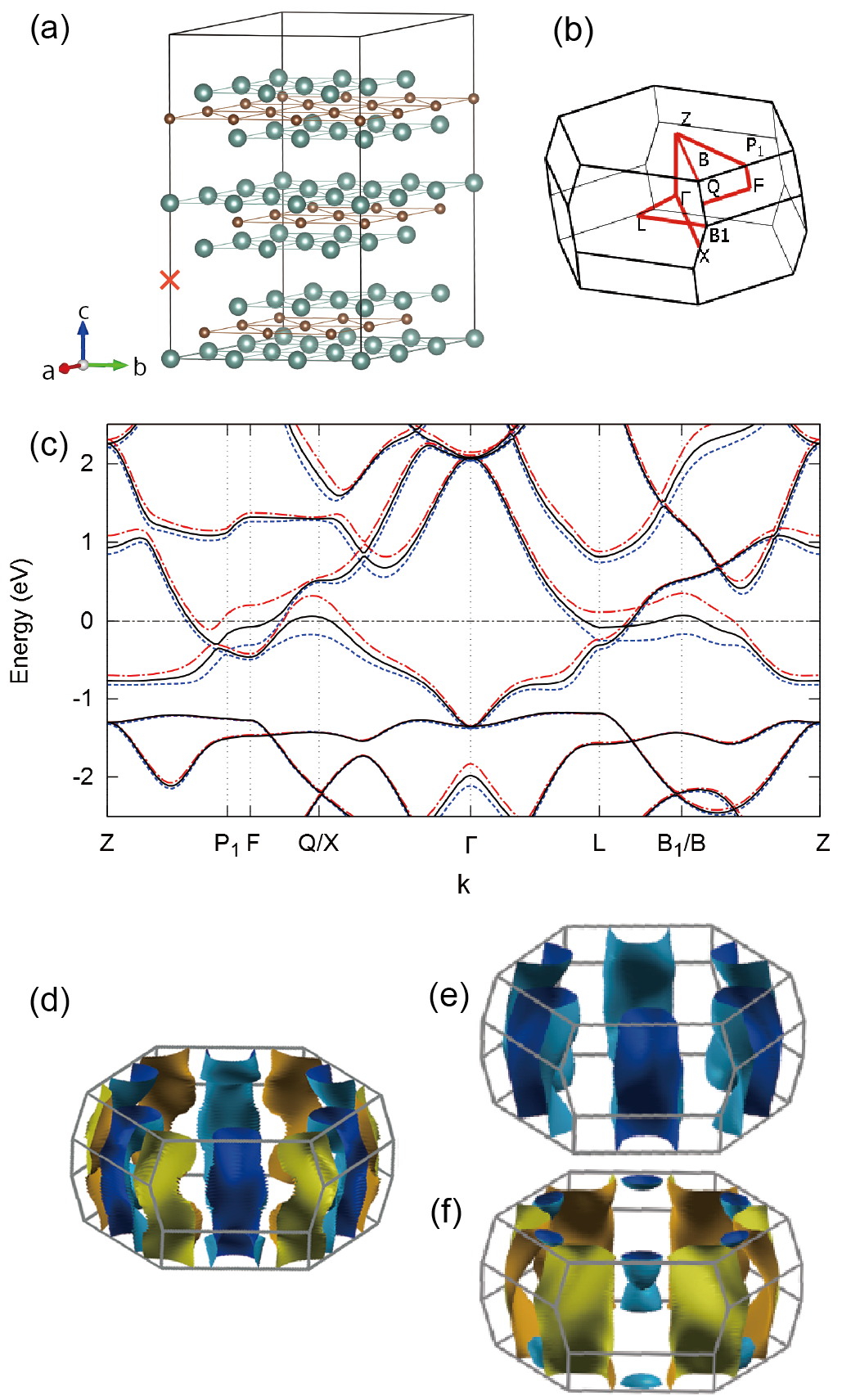
Structure: Figure 1(a) illustrates the crystal structure of Y2C. At2 ; Ma A conventional (hexagonal) unit cell of Y2C consists of nine atomic layers having the same triangular 2D lattice structure, albeit being staggered. The nine layers are grouped into three units, each made of three closely spaced layers (Y-C-Y) stacked with a layer separation of 1.35 Å. These units are separated by a distance (3.45 Å between Y layers) larger than that between layers within the same unit (1.35 Å between Y and C layers). Since the standard oxidation numbers of Y and C are +3 and -4, respectively, these layer units are positively charged ([Y2C]2+) and the excess electrons are accumulated between the units to form a quasi-2D electride.In ; Tad The whole crystal therefore has the [YCY]2e[YCY]2e [YCY]2+…. stacking structure. As shown below, the interlayer electrons are loosely bound around the interstitial sites [indicated by a red cross in Fig. 1(a)] and extend in the layer plane to form a 2D electron system.
Method of Calculation: We employed two density functional-based methods using exchange-correlation functionals in the generalized gradient approximation (GGA) : (1) the full-potential linearized augmented plane wave (FLAPW) method, as implemented in the All Electron Band Structure Calculation Package (ABCAP), Ham and (2) the projector augmented wave (PAW) method with a plane wave basis, as implemented in the Vienna Ab Initio Simulation Package (VASP).Kr ; Kr2 ; Bl ; Kr3 The FLAPW method takes into account all the electrons on an equal footing and is “the most accurate method for electronic structure at the present time.”Mar The PAW method treats core electrons as frozen and is therefore more efficient at the cost of losing some accuracy. In our calculations, the 2 and 2 orbitals of C and the 4, 4, 5 and 4 orbitals of Y were taken into account, while lower-energy orbitals were frozen and ignored. The specific GGA potentials used were PBEPBE and PW91 PW91 for (1) and (2), respectively. To reinforce these calculations, we also carried out plane-wave-based calculations using screened Heyd-Scuseria-Ernzerhof (HSE06) hybrid functional method,HSE ; HSE06 as implemented in VASP, which goes beyond the density functional theory by mixing PBE exchange and exact exchange.
For FLAPW calculations, we employed cutoff energies of 163 eV and 653 eV for the wave functions and charge/potential, respectively, and k-integration was carried out in the conventional (hexagonal) Brillouin zone (BZ) using a -centered sampling mesh. For PAW calculations, the plane waves were cut off at 800 eV, and integration over the primitive (rhombohedral) BZ was performed using a -centered mesh. The hybrid calculations were performed with cutoff energy of 400 eV and a sampling mesh of . For both spin-polarized and spin-nonpolarized cases, the structure was relaxed using the PAW method until the force acting on each ion became less than 0.7 meV/Å. The optimized structures were used in FLAPW and hybrid functional calculations.
| (meV) | () | (Å) | (Å) | |
|---|---|---|---|---|
| PAW + PBE 111 Ref. PBE, | 15 | 0.38 | 3.61/3.62 | 18.45/18.42 |
| FLAPW + PW91222 Ref. PW91, | 12 | 0.36 | - | - |
| HSE06 333 Refs. HSE, ; HSE06, | 17 | 0.33 | - | - |
Results and Discussion: Table I compares the total energy decrease resulting from spin polarization and the magnetization per primitive unit cell (Y2C) obtained by the three methods. Here, is defined as , where and denote the total energies calculated with and without spin polarization, respectively. As can be seen from the Table, the results obtained by different methods are in very good agreement and predict Y2C to be a weak itinerant ferromagnet. The optimized lattice constants and (last two columns of Table I) are virtually unaffected by spin polarization. Hereafter, we will focus on the results obtained by the PAW method unless stated otherwise.
Having two excess electrons per unit cell ([Y2C] 2e-]), Y2C would be a band insulator if there were no band overlap. The actual band structure calculated without spin polarization [black solid lines in Fig. 1(c)] is semimetallic with two conduction bands overlapping near the Fermi level (= 0 throughout this paper). This semimetallic band structure results in electron and hole pockets near the BZ edge. As can be seen from the plots of Fermi surfaces in Fig. 1(d), the electron pockets include the P1, F and L points, and the hole pockets include the QX and BB1 points at the boundary of the BZ. To identify the interlayer states, we placed an empty sphere of 1.8 Å radius at the interstitial site inside the interlayer gap [red cross in Fig. 1(a)] and projected the wave functions onto this sphere to obtain the partial density of states (PDOS) for the interstitial site. The result shown in Fig. 2(c) indicates that the interlayer states span a rather narrow energy range of -1 to +0.4 eV. Inspection of the charge density for these states reveals that it is indeed confined in the interlayer gap with a maximum of approximate symmetry at the interstitial site. Therefore, the interlayer band may be viewed as arising from the 2D lattice of overlapping virtual orbitals (quasiatoms) having symmetry at interstices. Figure 2 also presents the (a) total density of states (DOS) and (b) PDOS for Y. From the latter, one can see that the Y states are hybridized with the interlayer states near EF. An expanded plot (not shown) reveals that the overall bandwidth of the Y states is about 10 eV.

The inclusion of spin polarization splits the interlayer bands, as shown by the blue dashed curves (majority spin channel) and the red dash-dotted curves (minority spin channel) in Fig. 1(c), causing the DOS peak to split and shift away from , stabilizing the ferromagnetic state as can be seen in Figs. 2(a’)-(c’). As the peak shifts, its shape undergoes a larger distortion than normally observed in conventional itinerant magnets such as iron. In the ferromagnetic state, there is only one majority spin band crossing the Fermi level and this band has electron pockets enclosing P1, F and L [Fig. 1(e)]. For the minority spin channel, the lower conduction band has hole pockets enclosing QX and BB1, and the upper conduction band has small electron pockets slightly off P1 towards Z [Fig. 1(f)].
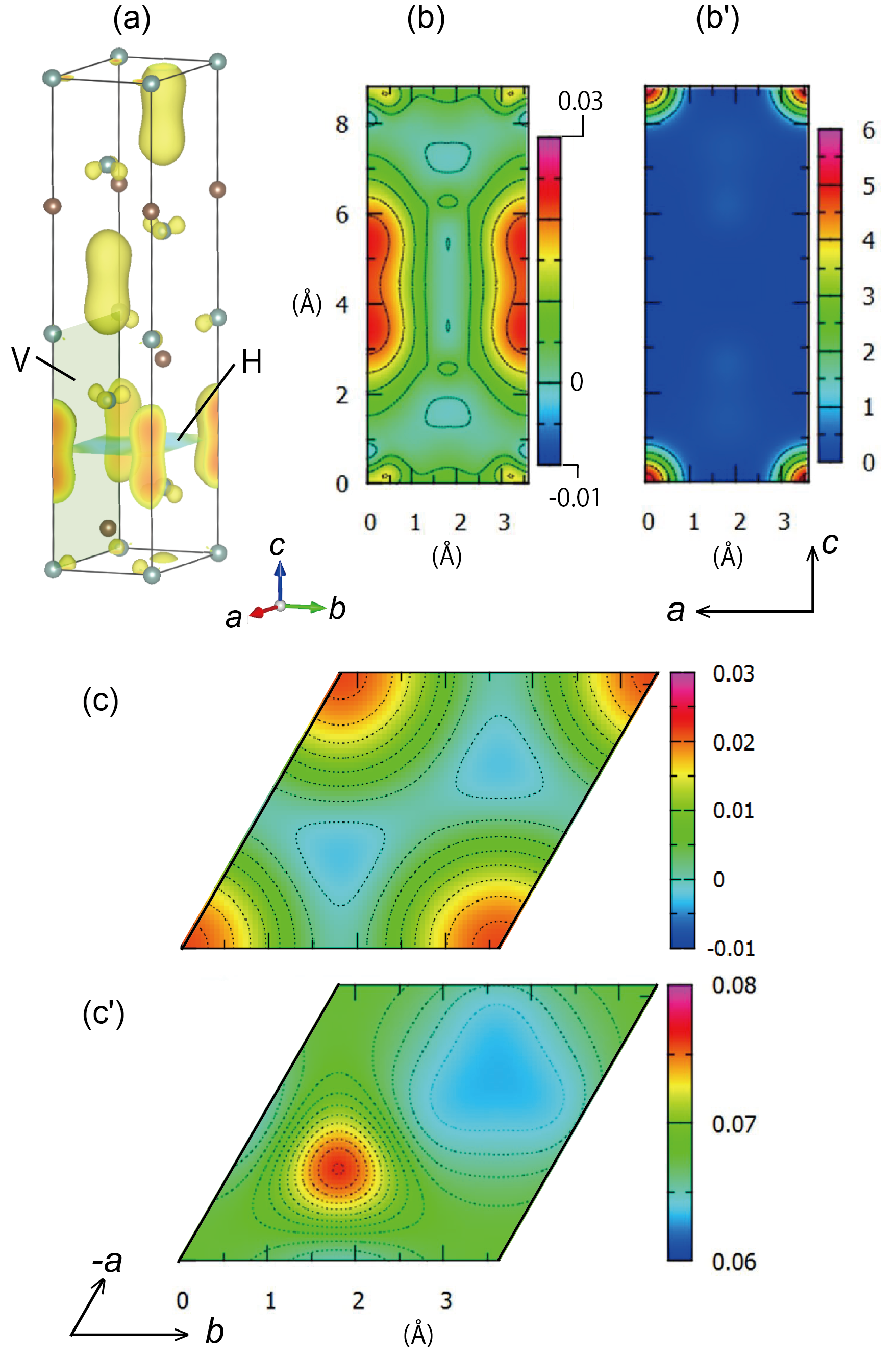
Figure 3(a) shows the magnetization density isosurface for the ferromagnetic state. Remarkably, the bulk of the magnetization is concentrated around the interstitial sites, while very small polarization exists at Y sites. (The Y ions are drawn with smaller spheres to make their polarization visible.) This can be seen more clearly in the cross-sectional plots of magnetization in Figs. 3(b) and (c). Here, (b) shows the cross section in the (001) horizontal plane [denoted as H in Fig. 3(a)] passing through interstitial sites at its four corners, while (c) depicts the cross section in the vertical plane denoted as V in Fig. 3(a). For comparison, corresponding plots of the charge density are shown in Figs. 3(b’) and (c’). It can be seen that the magnetization is concentrated in off-ion regions where the charge density has its maxima. The magnetic moment of Y ions (evaluated using the ionic radius for Y3+ of 0.9 Å) accounts for only 7.1 % of the total magnetization. This weak polarization of Y is likely to be the result of hybridization with the interlayer electrons. These features indicate that the ferromagnetism of Y2C is induced by the spin polarization of the electride electrons floating between the ionic layers.
This picture of ferromagnetism induced by off-ion electrons is unconventional. To ascertain that the electrons of Y are not playing the central role in the ferromagnetism, we also carried out calculations with on-site Coulomb interaction included in the Y orbitals. It was found that magnetization decreases, rather than increases, as is increased from 0, which would be difficult to understand if the electrons are driving the ferromagnetism.
In a wide range of itinerant ferromagnets, the ferromagnetism is understood to arise from a Stoner-type instability,St i.e., energy is lowered by the exchange splitting of a sharp DOS peak around . The criterion for this instability is where is the exchange parameter. This condition, derived originally using a simple molecular field argument postulating intra-atomic exchange, has been shown to be much more general and is applicable to both intra-atomic and more extended exchange interactions between the electrons.Kub This Stoner-type mechanism appears to operate in Y2C as can be seen from the DOS in Fig. 2.sh Recently, Pickard and Needs Pic have made an important prediction based on the density functional theory that the interstitial electrons in alkali metals at high pressures (also electrides) would exhibit a Stoner-type instability towards ferromagnetism. Our results indicate that the interlayer electrons in Y2C may show a similar instability at ambient pressure.
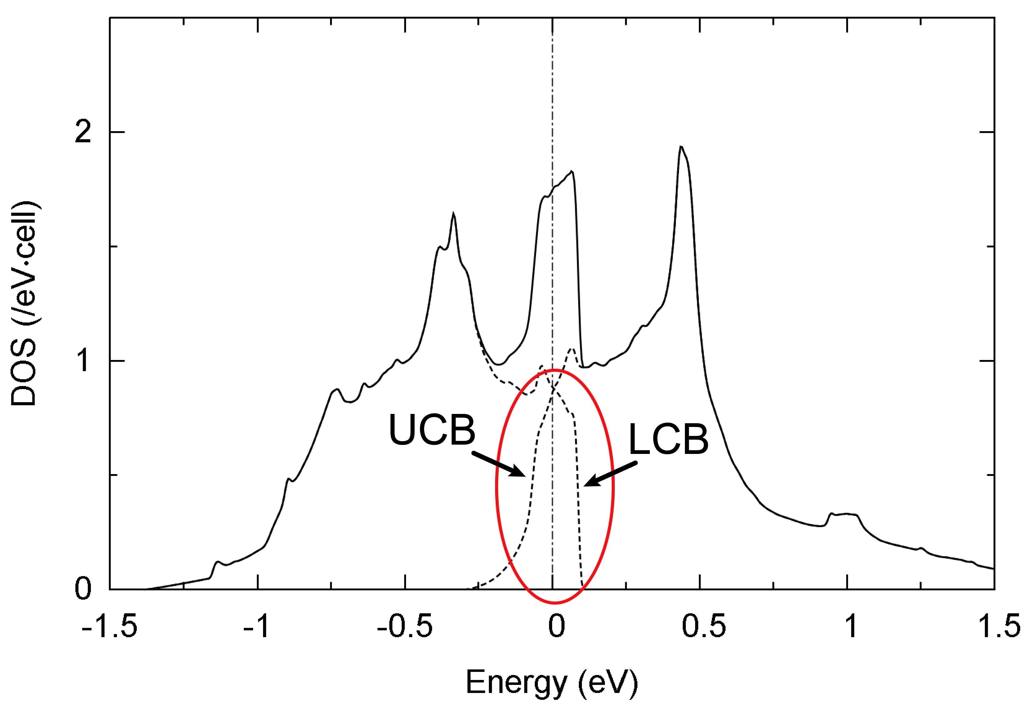
One may wonder what causes the DOS to have a peak around . The dashed curves in Fig. 4 denote the DOSs of the lower conduction band (LCB) and upper conduction band (UCB) for the spin-nonpolarized state. Both curves drop sharply to zero in a step function manner toward the edge (highlighted by a red circle), which is characteristic of a 2D electron system. As Y2C is a semimetal, the two bands overlap near and cause their sum (total DOS, solid curve) to have a peak at . Such an enhancement of DOS at is expected to occur generally in semimetals with 2D conduction bands.
In summary, ab initio calculations show the ground state of Y2C to be weakly ferromagnetic, where the ferromagnetism is induced by electride electrons accumulated in the interlayer void space. The magnetization measurement of polycrystalline Y2C by Zhang et al. Zh shows no ferromagnetic transition down to 2 K. It is not yet clear whether there is a transition at an even lower temperature or there is no transition. Even if the latter is the case, the system should be close to a ferromagnetic instability, and spin fluctuations associated with this instability may be observable as an anomaly in spin susceptibility (deviation from the Curie-Weiss Law) and specific heat, Mor or by techniques such as neutron diffraction and magnetic resonance. The sharp rise in susceptibility below 20 K observed by Zhang et al.Zh may signal such a fluctuation effect.
T. I. thanks Drs. Norio Ota, Susumu Saito and Xiao Zhang for useful discussions. This work was supported by the MEXT Elements Strategy Initiative to Form Core Research Center and the JST ACCEL Program. The Fermi surfaces were plotted by XCrySDen.XCr
References
- (1) J. L. Dye, Science 301, 607 (2003).
- (2) J. L. Dye, Science 247, 663 (1990).
- (3) Alkali metals under high pressures are also predicted to be electrides. See, for example, C. J. Pickard and R. J. Needs, Nat. Mater. 9, 624 (2010); M. Gatti, I. V. Tokatly, and A. Rubio, Phys. Rev. Lett. 104, 216404 (2010) and references therein.
- (4) C. J. Pickard and R. J. Needs, Phys. Rev. Lett. 107, 087201 (2011).
- (5) S.-W. Kim and H. Hosono, Philo. Mag. 92, 2596 (2012).
- (6) S. Matsuishi, Y. Toda, M. Miyakawa, K. Hayashi, T. Kamiya, M. Hirano, I. Tanaka, and H. Hosono, Science 301, 626 (2003).
- (7) K. Lee, S. W. Kim, Y. Toda. S. Matsuishi, and H. Hosono, Nature 494, 336 (2013).
- (8) A. Walsh and D. O. Scanlon, J. Mater. Chem. C 1, 3525 (2013).
- (9) T. Inoshita, S. Jeong, N. Hamada, and H. Hosono, Phys. Rev. X 4, 031023 (2014).
- (10) T. Tada, S. Takemoto, S. Matsuishi, and H. Hosono, Inorg. Chem. 53, 10347 (2014).
- (11) X. Zhang, Z. Xiao, H. Lei, Y. Toda, S. Matsuishi, T. Kamiya, X. Ueda, and H. Hosono, J. Chem. Mater. 26, 6638 (2014).
- (12) M. Atoji and M. Kikuchi, J. Chem. Phys. 51, 3863 (1969).
- (13) J. P. Maehlen, V. A. Yartys’, and B. C. Hauback, J. Alloys Compd. 351, 151 (2003).
- (14) N. Hamada, K. Terakura, and A. Yanase, J. Phys. F 14, 2371 (1984); A. Yanase and N. Hamada, J. Phys. Soc. Jpn. 68, 1607 (1999).
- (15) G. Kresse and J. Furthmüller, Phys. Rev. B 54, 11169 (1996).
- (16) G. Kresse and J. Furthmüller, Comput. Mater. Sci. 6, 15 (1996).
- (17) P. E. Blöchl, Phys. Rev. B 50, 17953 (1994).
- (18) G. Kresse and D. Joubert, Phys. Rev. B 59, 1758 (1999).
- (19) R. M. Martin, Electronic Structure: Basic Theory and Practical Methods (Cambridge University Press, Cambridge, 2005) p. 351.
- (20) J. P. Perdew, K. Burke, and M. Ernzerhof, Phys. Rev. Lett. 77, 3865 (1996).
- (21) J. P. Perdew, J. A. Chevary, S. H. Vosko, K. A. Jackson, M. R. Pederson, D. J. Singh, and C. Fiolhais, Phys. Rev. B 46, 6671 (1992).
- (22) J. Heyd, G. E. Scuseria, and M. Ernzerhof, J. Chem. Phys. 120, 7274 (2004).
- (23) A. V. Krukau, O. A. Vydrov, A. F. Izmaylov, and G. E. Scuseria, J. Chem. Phys. 125, 224106 (2006).
- (24) E. C. Stoner, Proc. Roy. Soc. London, A 165, 372 (1938); 169, 339 (1039).
- (25) J. Kübler, Theory of Itinerant Electron Magnetism (Oxford University Press, Oxford, 2000) Chap. 4.
- (26) This is consistent with our finding that the ferromagnetism of Y2C is suppressed by shifting away from the DOS peak in both positive and negative directions.
- (27) T. Moriya, Spin Fluctuations in Itinerant Electron Magnetism (Springer-Verlag, Berlin, 1985).
- (28) A. Kokalj, Comp. Mater. Sci. 28, 155 (2003). Code available from http://www.xcrysden.org/.