Developing Scintillation Light Readout Simulation for the SBND experiment
Abstract
Detection of scintillation light can play several important roles in LArTPCs. Increased collection efficiency could result in the improvement of time, energy, and position resolution. The SBND collaboration is developing detailed MC simulations to study the performance of different types of light systems in the LArSoft framework. Due to the vast number of photons typically produced in neutrino physics events, a full optical simulation becomes extremely hard to run on reasonable time scales. I will describe how the SBND simulation tackles these problems and its current status for two of the light detection systems considered by SBND: (i) a traditional TPB-coated PMT based system and (ii) a system based on TPB-coated reflector foils to increase collection efficiency without increasing the number of photodetectors.
keywords:
SBND; Scintillation light; Liquid argon1 Introduction
Free electron separation and VUV light emission are the two features that characterize the use of liquid argon (LAr) as active medium [1]. Both processes are complementary and their relative weight depends on the actual strength of the applied electric field. The free electron yield rises with the field value while the photon yield decreases due to a reduction of the recombination rates. At the typical field strength value of 500 both processes (ionization and scintillation) are relevant. The free electrons from ionization induce detectable signals on the wires of the Time Projection Chambers (TPC) during their drift motion towards and across the wire planes.
Depending on the performance of the light detection system (LDS), the detection of scintillation light can provide important information. Increasing collection efficiency results in the improvement of time, position and energy resolution, as well as in a lower threshold for the energy reconstruction. For a detector in a beam (as SBND [2]), prompt light signals can provide internal trigger formation, tagging events in phase with the neutrino beam. It can provide an effective method for an absolute time measurement, needed for the reconstruction of non-beam related events such as cosmic rays or supernova neutrinos. The light signals contain additional (complementary) information for total energy deposition reconstruction and for particle identification. There are additional opportunities offered by enhanced LDSs, for example, it is possible to determine the sign of the incoming neutrino through tagging of Michel electrons coming from stopping muons [3].
2 Components of the Light Detection System in SBND
An important part of the mission of SBND is to be an RD for future LAr neutrino experiments. Its relatively small volume makes it an excellent test-bed for new light detection system designs. The LDS components under evaluation for SBND include: traditional TPB-coated PMTs, TPB-coated reflector foils, and acrylic light guide bars read out at the ends with SiPMs. In this proceeding I will focus on the two first components mentioned above.
TPB-coated PMTs.
It has been demonstrated that a system
based on TPB-coated cryogenic PMTs works well in modest-sized
experiments (ICARUS [4], MicroBooNE [2]), but they are
difficult to scale to bigger ones (like DUNE).
TPB-coated reflector foils. Adapted from liquid argon dark
matter detectors, the installation of these foils inside the time projection chamber
volume enhance light collection without increasing the number of
photodetectors. A system of this type is currently implemented in the
LArIAT experiment [5].
In this work we present the methods being developed to benchmark these different components. In particular studying the effects of adding wavelength shifter covered reflector foils to an array of 3” diameter PMTs (154 units). In the next sections we will describe the workings of these simulations, and compare the first results, regarding the detection efficiency, obtained for the systems under evaluation.
3 The optical simulation in LArSoft
SBND simulations are performed within the open source LArSoft framework, which provides simulation reconstruction and analysis tools for current and future LAr TPC experiments. Basically, different detectors only require their own geometry definitions (in gdml format) and a small number of specific detector settings.
The simulation of the optical photons (production and propagation) in LArSoft incorporates two methods [6]. The full optical simulation implements the production and tracking of individual scintillation photons using Geant4. To produce a realistic detector response to the generated light, Rayleigh scattering, reflections, wavelength shifting and absorption are considered in the tracking of light. The huge number of photons typically produced in a neutrino physics event makes these simulations extremely slow and CPU consuming, taking on the order of hours or even days per event. An alternative fast optical simulation mode has been developed to overcome this problem for regular simulation tasks. This approach is based in the existence of a previously full-mode-built library of stored visibility data (visibility ratio between the number of produced and detected photons) to sample an expected detector response given an isotropic emission of light at some point in the active volume. Thus, for each energy deposition at each step, instead of generating Geant4 trackable optical photons, the fast scintillation mode predicts a certain number of these photons arriving to each optical sensitive volume. With this procedure, the simulation of an event typically takes minutes rather than hours to finish.
3.1 Optical library generation
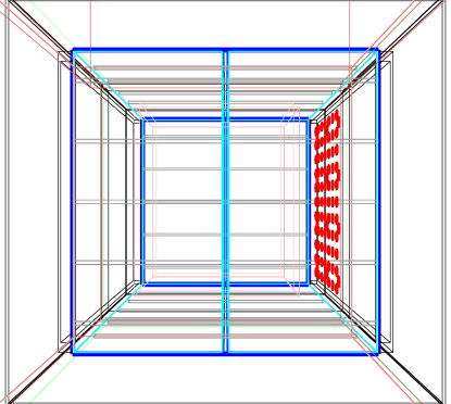
For the generation of the library required by the fast optical simulation, we divided the active volume of our detector into 3D pixels or voxels (voxelization). To have voxels with 5 in each dimension (x = 200 drift, y = 400 height and z = 500 length) we defined 40, 80 and 100 voxels in the x, y and z directions. Subsequently, 400k photons were randomly generated in each of these regions. This was done by a module in LArSoft that generates a source of an isotropically produced Geant4 photons from any specified area in the detector. This light was simulated following a gaussian energy spectrum centered at 9.69 and with a width of 0.25 to imitate the scintillation emission in liquid argon [7]. This resulted in an extremely large () number of photons to be tracked (with Rayleigh scatterings, reflections, absorptions and wavelength shiftings) with its consequent consumption of CPU and memory. To optimize the computational intensity required by this procedure, and making use of the symmetry in our geometry, we “switched-off” (removed from our simulations) the PMTs located in one half of the photocathode plane (z-y plane). A diagram of the geometry used for the generation of our library is shown in the figure 1. From the reduced library generated in this way, by trivial symmetry operations, we could built the completed library with all the needed components.
3.2 Arrival time distributions
The scintillation light emission in LAr is governed by its double exponential decay form (fast and slow components). The optical library method does not provide the arrival times of the detected photons which can be affected during direct transport and Rayleigh scattering. For a ”small” detector like SBND this is a second order effect, gaining in importance as the path traveled by the photons until being detected increases. The inclusion of these distributions into the library would explode the memory. Originally, the adopted strategy for the timing was to parametrize them as a function of the arrival time of the first photon, using only the information of the PMT location and the scintillation point. Therefore, no extra information was needed in the optical library. This works quite well for the case of the direct light. The reflected light is more complicated because there is no obvious (representative) traveled distance for this component. After several attempts to estimate the minimum average distance (arrival time of the first photon) for each pair “scintillation point - PMT”, we decided to include that piece of information into the library (without noticeable impact on the memory).
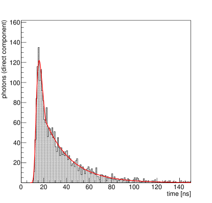
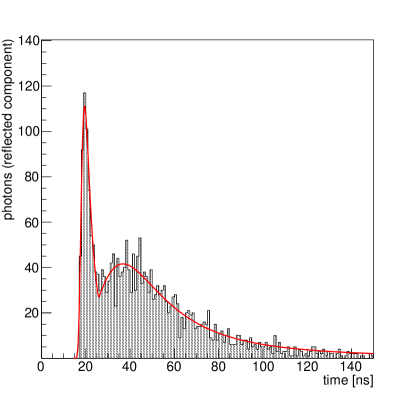
Figure 2 (left) shows a typical photon arrival time distribution for the direct light component. A prompt signal followed by a diffuse tail are clearly detectable. To model the shape of these distributions, we have used a gaussian plus an exponential function (red curve on the figure). An example of the time distribution for the reflected light component is shown in figure 2 (right). In this case, a sum of two landau functions has been the model adopted to describe their shapes. The next step would be to parametrize the parameters of the two selected functions with the minimum arrival time of a photon in each case111For the direct light component this is calculated simply by the ratio between the voxel-PMT distance and the group velocity of the VUV photons generated in the liquid argon scintillation.. At the time of writing this proceeding, these parametrizations are still work in progress.
4 Some preliminary results using the optical libraries
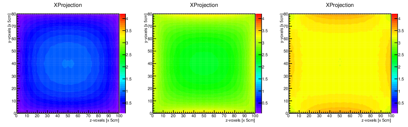
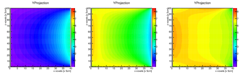
One way of testing the system is by using visibility maps across the detector. Figure 3 shows different examples. The XProjection and the YProjection histograms show the visibility summed for every optical detector projected down x (drift) and y (height) directions respectively. In other words, the XProjection represents the total probability of a photon to reach a PMT summed for every x at each (y, z) position. Thus, they are representations of the photon detection efficiency of our detector. In figure 3, the panels on the right have been obtained with a LDS consisting of an array of 154 3” diameter TPB-coated PMTs covering uniformly the photocathode plane together with TPB-coated reflector foils covering the active volume of the TPC (2 foils in the xy plane + 2 foils in the xz plane) and the cathode plane (2 foils in the yz plane). In a system like this, all recorded signals are a mixing of the direct and the reflected components of the generated scintillation light. If we remove the foils from our system, the only accesible component is the direct light. This is represented in the panels on the left. In the middle are shown the results for the reflected component alone. This latter case would be equivalent to a system with the foils where the PMTs are not coated by TPB. The main result derived from these figures is that a PMT-based LDS including reflector foils provides a more efficient and uniform collection of the scintillation light along the whole detector volume (by an average factor of the order of 3 and 6, respectively, relative to our design).
References
- [1] T. Doke, Fundamental properties of liquid Argon, Krypton and Xenon as Radiation detector media, Portgal Phys 12 (1981) 9.
- [2] R. Acciarri et al., A Proposal for a Three Detector Short-Baseline Neutrino Oscillation Program in the Fermilab Booster Neutrino Beam, arXiv:1503.01520 [physics.ins-det] (2015).
- [3] M. Sorel, Expected performance of an ideal liquid argon neutrino detector with enhanced sensitivity to scintillation light , JINST 9 (2014) 10002.
- [4] S. Amerio et al., Design, construction and tests of the ICARUS T600 detector, NIM 527 (2004) 329-410.
- [5] R. Acciarri et al., LArIAT: Liquid Argon In A Testbeam, arXiv:1406.5560 [physics.ins-det] (2014).
- [6] E. Baller et al., Liquid Argon Time Projection Chamber research and development in the United States , JINST 9 (2014) T05005.
- [7] T. Heindl et al., The scintillation of liquid argon, JEPL 91 (2010) 62002.