Enhancing the Performance of the T-Peel Test for Thin and Flexible Adhered Laminates
Abstract
Symmetrically bonded thin and flexible T-peel specimens, when tested on vertical travel machines, can be subject to
significant gravitational loading; with the associated asymmetry and mixed-mode failure
during peeling. This can cause erroneously high experimental peel forces to be recorded which leads to uncertainty in estimating
interfacial fracture toughness and failure mode. To overcome these issues, a mechanical test fixture has been designed for use with vertical test machines, that supports the unpeeled portion of the
test specimen and suppresses parasitic loads due to gravity from affecting the peel test.
The mechanism, driven by the test machine
cross-head, moves at one-half of the velocity of the cross-head
such that the unpeeled portion always lies in the plane of the instantaneous center of motion.
Several specimens such as
bonded polymeric films, laminates, and commercial tapes were tested with and without the fixture, and the
importance of the proposed T-peel procedure has been
demonstrated 111The supplementary videos can be obtained from http://web.mit.edu/npdhye/www/supplementary-videos.html or by emailing npdhye@gmail.com.
For details on adapting or using the T-peel fixture for testing applications contact npdhye@gmail.com .
Keywords: Peel Test, Mixed-Mode Fracture, Machine Design.
Notation
P is the force applied by the upper and lower grip in the symmetrical T-peel test schematic [N]
P’ is the vertical force applied by the upper grip in the asymmetrical T-peel test schematic [N]
P” is the vertical force applied by the lower grip in the asymmetrical T-peel test schematic [N]
Pt is the vertical force per unit width applied by the upper grip on the upper peel arm[N/m]
Po is the reaction force per unit width at the base on the upper peel arm [N/m]
Mt is the moment per unit width applied by the upper grip on the upper peel arm [N]
Mo is the reaction moment per unit width at the base of the upper peel arm [N]
Mf is the moment applied by the upper grip on the upper peel arm in the symmetric T-peel test [Nm]
Mb is the moment exerted on the upper peel arm near crack tip in the symmetrical T-peel test schematic [Nm]
is the rate of advance of crack tip [m/sec]
is the normal stress due to bending
is the angle made by the tangent at any point along the peel arm with respect to horizontal [rad]
is the yield strength of the material in tension [Pa]
is the Poisson’s ratio
E is the elastic modulus [Pa]
E’= is the plane strain elastic modulus [Pa]
t is the thickness of one peel arm [m]
w (or b) denotes the width of the peel specimen into the plane [m]
s is the coordinate along the peel arm [m]
I is the moment of inertia of beam out of plane [m4]
is the radius of curvature at any point on the beam [m]
is the curvature at any point on the beam [m-1]
U is the bending elastic energy [J]
Gc is the total critical energy release rate [Jm-2]
GIc is the critical energy release rate in mode I failure [Jm-2]
GIIc is the critical energy release rate in mode II failure [Jm-2]
GIIIc is the critical energy release rate in mode III failure [Jm-2]
k is a user defined constant [m-2]
is the vertical force on the upper grip in the asymmetric T-peel test [N]
is the vertical force on the lower grip in the asymmetric T-peel test [N]
is the horizontal force on the upper grip in the asymmetric T-peel test [N]
is the horizontal force on the lower grip in the asymmetric T-peel test [N]
is the moment at the upper grip in the asymmetric T-peel test [N m]
is the moment at the lower grip in the asymmetric T-peel test [N m]
is the phase angle during mixed-mode cracking [rad]
is mode I stress intensity factor [Pa]
is mode II stress intensity factor [Pa]
is the weight of the peel specimen [N]
is the internal shear force parallel to the surface of upper peel arm [N]
is the internal shear force parallel to the surface of lower peel arm [N]
is the internal normal force on the surface of upper peel arm [N]
is the internal normal force on the surface of lower peel arm [N]
is the internal moment acting on upper peel arm [N m]
is the internal moment acting on lower peel arm [N m]
is the moment due to weight on the tail of the specimen [N m]
is the internal moment on the tail of the specimen [N m]
is the internal moment in reaction to gravity [N m]
is the internal moment in reaction to gravity [N m]
X, X’, and X” are the distances of different sections of peel specimen from line of
action of vertical forces [m]
Xmax is the maximum span of the peel arm in x-direction [m]
Ymax is the maximum span of the peel arm in x-direction [m]
Y1 and Y2 are the distances of the upper and lower grips from the shown section of the peel specimen [m]
is the length of the peel arm [m]
effective fracture surface energy [N/m]
is the irreversible work per unit area of crack advance [N/m]
density of the polymer [kg/m3]
normal stress in the vicinity of the crack tip [Pa]
shear stress in the vicinity of the crack tip [Pa]
I INTRODUCTION
The peel test is a common simple mechanical test for measuring adhesion strength in various applications, especially bonded thin and flexible laminates, and it can be performed in several different ways. The procedure usually consists of a laminate bonded to another laminate or to a thick substrate, and the test is conducted by pulling the laminate off the laminate or substrate at some angle while recording the peeling force in the steady-state during debonding. The usual goal is to relate the experimentally-obtained peel force to the intrinsic fracture toughness of the interface, where the interface toughness represents the work required per unit area to advance a crack at the interface and has the units J/m2 or N/m. Only in restricted scenarios can the peel force give a direct estimate of interface toughness. In general, the peel force is affected by the sample geometry, constitutive properties of the laminates, interfacial properties, and the test apparatus.
Depending on the application, several existing ASTM Astmd903 (a, b); Ast ; AST (a, b, c, d) or ISO standards ISO (a, b, a, c, d) are commonly employed for measuring adhesion through peeling. These standards can be easily practiced on various commercially available fixtures, such as 90∘, 180∘, climbing drum, floating roller, adjustable angle, and German rotating wheel peel fixtures Adm ; Ins (a); Mec .
Amongst the earliest attempts, two approaches for analyzing peeling were adopted: (i) energy based criterion, and (ii) stress based criterion.
The energy approach can be traced to work by Rivlin where strip detachment under the effect of weight was investigated. The stress-based criteria assumed that the failure occurred when the tensile stress in the adhesive interlayer exceeded the tensile strength due to peeling. The first theoretical analysis of peeling was presented by Spies Spies (1953). Here, the non-bonded part of the peeling strip was treated as an elastica, and the bonded part of the peeling strip was treated as an elastic beam on an elastic (Winkler) foundation of the adhesive layer. The failure criterion was based on the tensile stress exceeding the tensile strength of the adhesive interlayer. This approach implicitly assumed that rupture did not occur at any of the interfaces but rather in the bulk of the adhesive; the adhesive was assumed to behave as a Hookean solid up to the point of rupture, and stress concentrations at the strip edges were disregarded. Spies Spies (1953) recognized the role of plastic deformation during peeling strip and used an average elastic constant to account for the ductile behavior of the strips.
Since then, several investigations similarly treated the unbonded part of the flexible laminate as an elastica, whereas the bonded part as an elastic beam on an elastic foundation. Bikerman Bikerman (1957) considered 90∘ elastic peeling of the adherend with explicit solutions for Newtonian interlayer flow as well as cohesive failure of a Hookean interlayer. Jouwersna Jouwersma (1960) presented a refinement over Bikerman’s model. Kaelble Kaelble (1959) considered elastic peeling and emphasized the roles of cleavage and shearing mechanisms of failures during peeling and their effect on the peel force, and later reported rate effects in peeling Kaelble (1960). Yurenka Yurenka (1962) considered the peeling of the adhesively bonded metal, and analyzed several peeling configurations such as an edge bending load peel test, T-peel test, four-inch diameter drum peel test, four foot diameter drum peel test, and climbing drum peel test. Nicholson Nicholson (1977) considered the effects of large bending deformations of the beam during peeling.
The condition for the fracture of an adhesive joint during peeling using an energy balance (or energy theory of fracture) was presented by Kendall Kendall (1971). Subsequently, Kendall studied the rate effects during viscoelastic peeling Kendall (1973a) and the dependence of the peel force on adhesive surface energy and elastic deformation of the adherend Kendall (1973b, 1975). Chang et al. Chang (1960) employed a linear viscoelastic model to describe the constitutive behavior of the adherend and presented approximate solutions for several peeling configurations. Chen et al. Chen and Flavin (1972) were the first to consider the elastic-plastic behavior in peeling but used the tensile strength criterion for modeling the adhesive failure. Chang et al. Chang, Devries, and Williams (1972) considered an elastic-perfectly plastic analysis for adhesive failure, and accounted for the energy dissipation during plastic bending.
Gent et al. Gent and Hamed (1975) highlighted the difference between the energy-based and stress-based criteria for failure in peeling, and they indicated that the plastic deformation of the flexible members during peeling could account for an enhanced peel force. In another study Gent and Hamed (1977), effects of plastic deformation in 90∘ and 180∘ were considered, and an approximate analysis of elastoplastic peeling was presented. A numerical solution of elastoplastic peel problem has been given by Crocombe and Adams Crocombe and Adams (1981), and stress fields ahead of the crack tip were later studied Crocombe and Adams (1982). The role of residual strain energy in elastoplastic peeling was emphasized by Atkins et al. Atkins and Mai (1986). Kim et al. Kim and Aravas (1988); Aravas, Kim, and Loukis (1989) comprehensively studied the elastoplastic peeling from a rigid substrate, and estimated the energy dissipation due to inelastic bending in the peel arm. To estimate the true interfacial fracture energy, a correction scheme of subtracting the structural dissipation from total external work was proposed. In related studies Kim and Kim (1988); Kim, Kim, and Kim (1989), similar elastoplastic peeling of the adherends was considered, energy losses due to viscoelasticity were analyzed, and experimental results were reported. Kinloch et al. Kinloch, Lau, and Williams (1994) employed beam theory models to investigate the elastoplastic deformation in peeling, and they analyzed the role of finite beam rotation at the base of peeling arm.
Wei and Hutchinson Wei and Hutchinson (1998) were the first to report cohesive zone stress effects on the plastic deformation of the adherends near the peeling front and its effect on the elevated levels of peel forces. It was shown that, if the maximum cohesive stress along the interface was greater than about three times the yield stress of the laminate, the steady-state peel force considerably increased. Larger cohesive stresses lead to a dominant tri-axial stress state near the peeling front, and a simple beam model is no longer appropriate to describe the deformation of the adherend. Yang et al. Yang, Thouless, and Ward (1999, 2000) studied the T-peel while accounting for excessive plastic deformation in the adhesively bonded laminates, and they used embedded process zone models for fracture. Thouless et al. Thouless and Jensen (1992) studied the mixed-mode effects during the peeling of an elastic adherend from an elastic substrate. In addition, De Lorenzis et al. De Lorenzis and Zavarise (2008a) employed finite element analysis for mixed-mode debonding of laminates from rigid substrate in the peel test. Yang et al. Yang and Thouless (2001) analyzed the mixed-mode fracture of plastically deforming adhesive joints. Williams et al. Williams and Hadavinia (2002) employed cohesive zone models and presented solutions for the peeling of a cantilever beam specimen bonded to an elastic foundation. Su et al. Su, Wei, and Anand (2004) developed an elastic-plastic interface constitutive model and successfully applied it to various geometries such as T-peel test, four-point bend experiments on bonded bi-layer edge notch specimens, and lap shear experiments. Zhang et al. Zhang and Wang (2009) also developed numerical models for adhesives. Hadavinia et al. Hadavinia et al. (2006) performed a numerical analysis of elastic-plastic peel tests (90∘ and T-peel) and tapered double cantilever beam specimens.
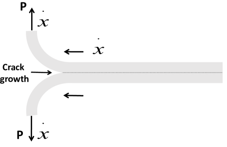
This study deals with a particular type of peel test, known as a T-peel test (T indicating that the specimen forms a T-shape) between symmetrical interfaces. The T-peel test has been practiced for at least the past six decades de Bruyne NA (1951). For discussions, we shall refer to an ideal T-peel test which assumes the following:
(i) The two symmetrical halves are joined together with an infinitesimal (or nearly zero thickness) intermediate layer.
(ii) Crack propagation occurs on a predefined path between the two symmetrical halves through the intermediate layer.
(iii) Under symmetrical loading, the two halves separate purely by opening with GIc as mode I fracture energy per unit area of crack propagation.
(iv) The peeling force during the test is not affected by gravity.
Figure 1 shows an idealized T-peel scenario with symmetric loading and material properties across the interface. We shall frequently drop the letter T, but the reference to the T-peel test is implied. During the steady-state crack propagation, if ‘P’ is the debonding load (N), ‘w’ indicating the specimen width (m) into the plane, and is the velocity (m/s), then the rate of total external work is given by:
| (1) |
From the work energy balance, under the assumptions of quasi-static (no kinetic energy) and steady-state conditions (elastic energy stored in the peel arm is constant), the rate of total external work () during the crack propagation equals to the sum of rate of work due to interface debonding and any dissipation associated with the specimen deformation (say, plastic deformation due to bending of arms, discussed in detail in Section VII.1). If and denote the debonding and dissipative energies, respectively, per unit area of crack advance, then
| (2) |
Therefore,
| (3) |
Note, refers to the dissipative work in the specimen other than within the interfacial region, and the effect of crack tip inelasticity is included in , i.e., represents the sum of the reversible and associated irreversible work necessary for crack advance at the interface Irwin (1958); Orowan (1945). A clear distinction between and may not always be straightforward in the scenarios when the regions of structural plasticity and crack tip plasticity overlap.
as well as can depend on numerous factors including test conditions and material constitutive properties, but they attain constant values during steady-state peeling. If is not equal to zero then we must subtract the work corresponding to from , to arrive at the correct interface toughness (). If then the peel force gives a direct measurement of the interfacial fracture energy. In particular, if is zero, and symmetrical loading and material properties prevail on both sides of the interface such that the failure of the interface occurs purely by opening mode, then ) represents the mode I fracture toughness (GIc) of the interface. However, if the peel force exceeds the elastic limits, then failure is accompanied with plastic deformation in the structure, which is intrinsically not connected to the interfacial fracture and therefore is not equal to zero (equation 2). In such cases, the peel force is not a direct measure of adhesive fracture energy.
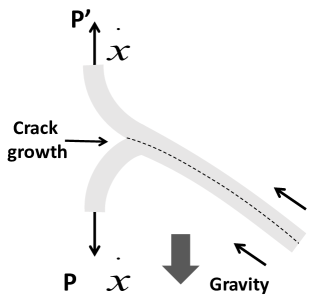
The T-peel test is quite straightforward to perform: the unbonded parts of the two flexible laminates are clamped in the grips of a mechanical tester and separated. If the test is performed on a vertical mechanical tester, the bottom grip is usually held fixed, whereas the top grip moves upwards. In this vertical configuration, gravity can have following effects: (i) a contribution to the measured peel force due to specimen’s weight, and (ii) an asymmetric T-peel configuration (particularly when a specimen is thin and flexible). This is shown schematically in Figure 3. In this situation, the contribution to peel force to specimen weight and, the bending of the freely suspended end and the degree of anti-symmetry introduced, depend on the geometry (i.e. length, width, and thickness) and the material properties (i.e. density, modulus, etc.) of the specimens. One can imagine critical scenarios where the bending action of the gravity may induce plastic deformation in the lower peel arm. All these effects could lead to a significant deviation in the measured peel force compared to the ideal T-peel. The uncertainty in the asymmetry during such a test is uncontrolled, since the degree of mode-mixity (or phase angle) is unknown (discussed in section II), and therefore no straightforward correction is possible for the same.
Recently, there have been some studies on the role of asymmetry in T-peel specimens Hirai et al. (2009); Choi and Oh (2001). Dolah et al. Dolah and Miyagi (2014) have proposed a horizontal-pull testing apparatus to perform the T-peel in a layout such that the tail of the specimen aligns with the gravity. However, the mechanics of T-peel in this vertical-tail layout has not been discussed.
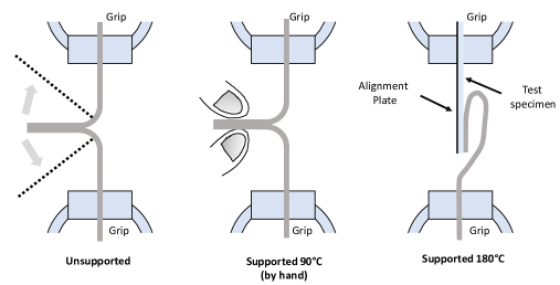
To the best of our knowledge, issues associated with T-peel testing of thin and flexible laminates on vertical test machines have not been resolved, and no testing fixture has been reported to perform it with sufficient precision. Figure 2 schematically shows a peel test procedure adopted by the medical packaging industry med , where the ASTM F88/F88M-09 standard is also referred. In the ASTM standard F88/F88M-09 AST (d), it is acknowledged that during a peel test a portion of the peel force may be due to bending component and not the “strength” alone, and that numerous fixtures and techniques have been devised to hold samples at various angles to the pull direction to control this bending force. However, the recommendation to compensate for the tail hangover during peel test is through hand support. It is quite evident that any such manual endeavor can itself introduce parasitic forces.
Even the commercial testing demonstrations Ins (b, c, d) do not make any recommendation for avoiding the issues caused by the gravity. Instron® Ins (d) proposes to use the ASTM D1876-08 AST (a) standard for the peel test, and states that “this method caters to the determination of the comparative peel or stripping characteristics of adhesives bonds when tested on standard-sized specimens under defined conditions of pretreatment, temperature, and testing speed. Typical results include ‘Average Load between 2 points’. This test can be performed on single column and dual column test frames.” The ASTMD 1876-08 peel test standard states that “this test method is primarily intended for determining the relative peel resistance of adhesive bonds between flexible adherends by means of a T-type specimen using a tension testing machine. The bent, unbonded ends of the test specimen shall be clamped in the test grips of the tension test machine, and a load of a constant head speed shall be applied. An autographic recording of the load versus the head movement or load versus distance peel shall be made. The peel resistance over a specified length of the bond line after the initial peak shall be determined.” No reference to account for specimen’s weight, effects such as gravity-induced asymmetry and mixed-mode failure, plastic bending, or suggestion for using a fixture for more accurate testing are made. Other examples of commercial testing procedures (where no reference to these effects has been made) can be found in vid (a, b). In Peterson , common problems with tests in relation to adhesion are discussed, but no reference to issues related to effects on the T-peel test due to gravity is made. Similarly, in several other T-peel experimental studies on relatively thin laminates Gardon (1963); Gent and Petrich (1969); Gent and Lai (1994), no reference to these effects is made.
In addition to its simplicity, an ideal T-peel test can be employed to estimate the mode I fracture toughness () of thin and flexible laminates. However in other peel test procedures, such as 90∘ peel test (for e.g. ASTM D6252 standard Ast ), etc. when the symmetry across the bonded interface is broken; cannot be determined.
To overcome limitations of current test methods, we have designed a mechanical fixture that suppresses the action of the gravity on T-peel tests performed on vertical test machines. This study has been motivated by our recent work Padhye et al. (2015a), where authors identified a compelling case such that the gravity showed a significant effect, and correct estimation of mode I fracture toughness was not possible. Next, we review the stress fields associated with the crack tip, mix-mode failures, energy release rates, and other concepts relevant to the peel test.
II PEELING AND FRACTURE MECHANICS
In case of two-dimensional geometries, when the material properties are symmetrical across the interface and loading leads to pure opening displacements, then only normal stresses act across the plane ahead of the crack tip, and fracture is referred to occur in mode I. The fracture toughness in such cases is normally denoted by .
However, an asymmetry in the material properties or loading results in shear stresses ahead of the crack tip and a mixed-mode failure (comprising of both opening and shearing displacements). The fracture toughness () in a mixed-mode then depends upon the relative amounts of opening and shearing deformations. A mixed-mode toughness is usually greater than pure mode I toughness ().
As per linear elastic fracture mechanics,
a singular stress field is associated with the crack tip when
traction-free line crack exists. This can be expressed compactly by using
complex number notation in terms of
mode I () and mode II ()
stress intensity factors as follows:
| (4) |
In the above equation 4, and depend linearly on the applied loads and on the details of
the full geometry of the body. If denotes the plane strain tensile modulus, then the total fracture toughness in terms of and , as per Irwin’s result, can be written as follows:
| (5) |
The relative magnitudes of and are usually expressed in terms of
a phase angle as:
| (6) |
The mixed-mode fracture toughness is usually a function of and it can be expressed as . Here, the subscript c denots the critical energy release rate during steady-state cracking. It is essential to emphasize that even in the presence of material symmetry, if an asymmetric loading occurs across the interface, then the interface toughness will be a function of the phase angle (which will itself depend upon the overall loading configuration). Only when symmetric material properties and loading occur across the interface, can the mode I fracture toughness (GIc) be estimated. For a detailed study on mixed-mode failures, the readers are referred to Suo and Hutchinson (1990); Hutchinson (1990).
When T-peel tests are performed on vertical test machines with adherends exhibiting small bending stiffness, then gravity can introduce a major asymmetry. This leads to a mixed-mode failure. In addition, the asymmetry can affect by causing structural plasticity in the lower peel arm due to bending under its own weight. During the peel test, the overhanging tail end of the specimen shortens; therefore, the degree of asymmetry varies. Due to these variations, no straightforward correction is possible and the determination of the interface toughness is uncertain. We emphasize that even if we know the specimen’s weight, there is no straight-forward method to account for the uncertainties associated with the asymmetric configuration. See Appendix for details on mechanics of symmetric and asymmetric T-peel test.
III DESIGN OF A T-PEEL TEST FIXTURE FOR VERTICAL CROSSHEAD TRAVEL MACHINES
During a T-peel test on a vertical machine, the two peel arms of the T-peel specimen are clamped in the upper and lower grips. In general, the lower grip is stationary, and the upper grip moves upwards. To support the specimen weight and maintain the symmetry of the T-peel specimen, a mechanism is needed that supports the freely hanging end of the specimen and moves upwards at a velocity half of that of the upper grip. Figure 4 shows such a mechanical fixture mounted on a vertical mechanical tester.
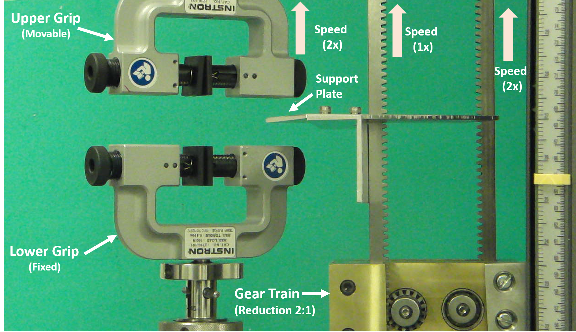
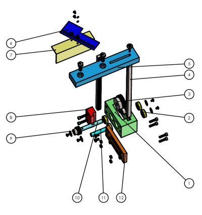
The peel test fixture uses a 2:1 speed reduction to cause the platform that supports the specimen to move at half the speed of the moving cross-head. A driving rack that is attached to the cross-head of the test machine drives the first spur gear of diameter . The first spur gear of diameter is meshed with a second spur gear of diameter . The second spur gear is mounted on the shaft which carries a third spur gear of diameter . The third spur gear drives the driven rack; hence the driven rack moves at half the speed of the driving rack. The driven rack is coupled to the plate that supports the overhanging tail of the peel specimen. As shown in the figure, the driving rack moves up at twice the speed of the driven rack. This causes the support plate attached to the driven rack to move at half the speed of the cross-head. We incorporated several holes/attachment points/or grooved slots on the driven rack such that the vertical and horizontal positions of the base plate could be adjusted before the start of the test. The mechanical fixture and its solid model are shown in Figure 5.
| Item No. | Part Description | Qty. |
|---|---|---|
| 1 | Gear Box | 1 |
| 2 | Bearing | 4 |
| 3 | Spur Gear (24 teeth) | 1 |
| 4 | Rack | 2 |
| 5 | Top Support Hanger | 1 |
| 6 | Film Support Plate | 1 |
| 7 | Connecting Bracket | 1 |
| 8 | Rack Retainer | 1 |
| 9 | Spur Gear (12 teeth) | 2 |
| 10 | Shaft (driven end) | 1 |
| 11 | Shaft (driving end) | 1 |
| 12 | Support Bracket | 1 |
From the experimental viewpoint, it is important to ensure that the crack front is sufficiently far from the nearest edge of the support plate. However, it should not be too far either, as the gravity-induced bending effects may appear on the part of the specimen lying between the crack and the nearest edge of the support plate. In addition, one must ensure that the peel arms are not constrained by contact with the peel fixture. If the frictional resistance arising from contact between the specimen tail and support plate were significant, an air-bearing support can be introduced El-Aguizy et al. (2005). However, in the current application where the tapes are very lightweight, the resulting effect of the frictional drag force would produce a fraction of a percent error and thus we did not see a need for a frictionless platform support.
IV EXPERIMENTS, RESULTS AND DISCUSSIONS


Methods and Materials
We considered several flexible adhered systems and, conducted T-peel tests on each system with and without using the peel fixture. The following adhered systems were chosen: (1) three roll-bonded laminates, namely, sample ‘A’ ( mm wide), sample ‘B’ ( mm wide) and sample ‘C’ ( mm wide). The specimens were made from Hydroxypropyl Methylcellulose (HPMC) of grade E 15 and Polyethylene glycol (PEG)-400, with 42.3% (Wt. %) of PEG in films. The samples ‘A’,‘B’ and ‘C’ were roll-bonded at a nominal plastic strain of 14.07%, 23.3% and 27.5%, respectively. For complete details see Padhye ; Padhye et al. (2015b, a), (2) two bonded layers of a commercial duct tape ( mm wide), (3) two bonded layers of a Scotch brand cellophane tape commonly used in the office ( mm wide), (4) two layers of Teflon glued together with EVA ( mm wide), (5) two layers of Teflon glued together with a silicone encapsulant adhesive ( mm wide), (6) two layers of self-adhering commercial vinyl laminates ( mm wide), (7) two layers of self-adhering commercial vinyl laminates (with backing 1 and mm wide), and (8) two layers of self-adhering commercial vinyl laminates (with backing 2 and mm wide). Peel tests were performed at a cross-head speed of 15 mm/min.
For all adhered systems, the experiment was first initiated in presence of the fixture to support the specimen’s tail end, and corresponding force versus displacement curves were recorded until a steady-state was achieved. Once a sufficient amount of data was sampled in the steady state with the fixture, the experiment was paused, the fixture was disengaged, the support for the tail end of the specimen was removed, and the test was re-initiated from the same point onwards while recording the corresponding load versus displacement curves. By removing the support, flexible adherends experienced a significant asymmetry due to the action of gravity.
| S. No. | T-peel Specimen | % Overestimation∗ |
|---|---|---|
| 1 | Roll Bonded Laminates Sample ‘A’ | 85.65 |
| 2 | Roll Bonded Laminates Sample ‘B’ | 54.66 |
| 3 | Roll Bonded Laminates Sample ‘C’ | 62.48 |
| 4 | Duct-Tape | 6.88 |
| 5 | Cellophane-Tape | 7.35 |
| 6 | Teflon-EVA-Teflon | 31.79 |
| 7 | Teflon-silicone-encapsulant-Teflon | 24.41 |
| 8 | Vinyl-Vinyl | 3.51 |
| 9 | VinylLaminate1-VinylLaminate1 | 7.46 |
| 10 | VinylLaminate2-VinylLaminate2 | 1.19 |
| ∗ %Overestimate = | ||
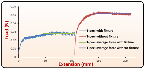
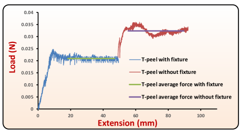
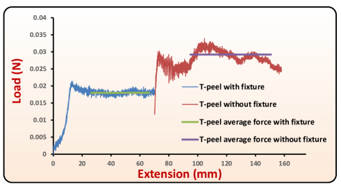
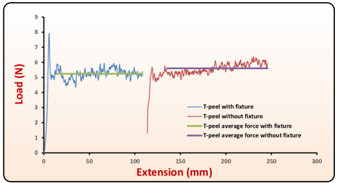
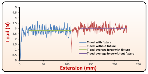
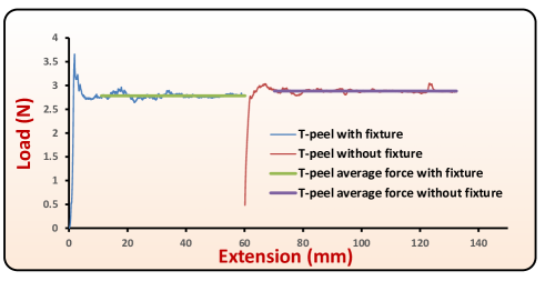
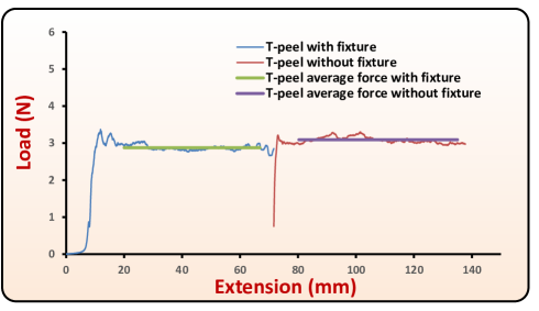
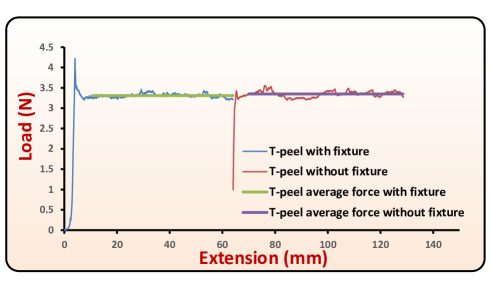
Figure 6 shows a snapshot of the T-peel test on roll-bonded laminates sample ‘A’ where the gravity effect has been suppressed due to the base support of the mechanical fixture. Figure 7 shows the peel test on the same specimen without the support, such that action of gravity is dominant and introduces significant asymmetry. The corresponding peel force versus displacement curves for the two cases are shown in Figure 8. The average peel force was calculated in the steady state region by neglecting the initial or final peaks (or jumps) and plotted with a solid line over the corresponding range. In the case of roll-bonded laminates sample ‘A’, the average peel force in the asymmetric case is significantly (approximately 85.65%) higher than the average peel force with the use of the fixture. The peel force versus displacement curves for roll-bonded samples ‘B’ and ‘C’ are shown in Figures 9 and 10, respectively, and also show an increased unsteady peel force when tested without the fixture. As mentioned above, the notion of steady state in the asymmetric case is ill-defined because the overhanging length of the tail specimen decreases as the test proceeds; however, the average in the peel force is still calculated in the asymmetric regime. We emphasize that a larger peel force (measured by the load cell at the upper gripping end), when tested without the fixture can be attributed to the mixed-mode failure, the specimen weight, possible plastic bending, etc., and there is no straight-forward method of precisely quantifying the contribution of each factor in the increased peel force. If we the consider the case of roll bonded specimen case ‘A’, with a total length (L) of mm, width (w) of mm, thickness (2t) of mm and density () of 1180 Kg/m3, then the specimen weight due to the upper peel arm (Lwt) works out to be N. The peel forces in the symmetrical and asymmetrical cases were N and N, respectively. Thus, the increase in peel force, approximately N, is greater than the weight of the upper peel arm. Since the increase in the peel force, from symmetrical to assymetrical case, is not alone due to the weight of the peel arm clamped at the load sensing grip, no straight-forward correction is possible. Also, in our experimental results, we achieved a steady state force in the symmetrical phase with relatively short length of peel arms, and the weight of the part of peel arm which was unsupported by the fixture was noted to be almost an order of magnitude lower than the steady-state peel force. This indicates that our proposed symmetrical test is quite close to the idealized T-peel test (symmetrical test in the absence of gravity). A detailed discussion on the effect of the weight of the peel arm in the symmetrical T-peel is given in Section VII.1.1.
In the asymmetric peeling, a low modulus and thin film is likely to bend more, due to which the mode II component will increase. As the mode II component increases, the effective toughness is likely to increase De Lorenzis and Zavarise (2008b); Reeder and REWS (1990). Note that the load versus displacement curves in the asymmetric case also show a slight lowering trend during the asymmetric part of the test, and the following reasons could possibly account for the lowering in peel force: (i) the total energy of an elastica is finite and constant, and in the symmetric case, the tail of the specimen carries no elastic energy; therefore, the rate of work performed by external force exactly balances the interface toughness. However, in the asymmetric case, the tail end bends due to its own weight and possess some elastic energy. As the tail is drawn in, it releases its elastic energy, which would be available for cracking. (ii) It is evident that greater asymmetry leads to more pronounced component of mode II; thus, when the tail end is long and asymmetry due to bending is high, the degree of interfacial shearing is dominant with respect to interfacial opening. However, as the tail shortens by being drawn into the crack tip, the mode II component decreases, and therefore, the peel force decreases. In our experiments, it was also observed that the light weight samples, when tested without the fixture, suffered noticeable dynamic instability due to air currents, i.e., the samples were observed to shake and sometimes flutter. Such instabilities could also introduce undesired mode III parasitic effects of failure, and contribute to the increase in the peel force. This could also explain the rising trends in the recorded peel forces during the asymmetric testing. The use of support plate prevented such instabilities from occurring, and a very good steady state was noted during the symmetric part of the test. Further design modifications can be made to the support plate to eliminate any further unwanted effects of air-current on the testing of extremely delicate and highly sensitive samples. An example would be the presence of a channel on the support plate where the specimen tail can reside. The summary of % overestimation in the average peeling force with and without using support, are listed in Table 2.
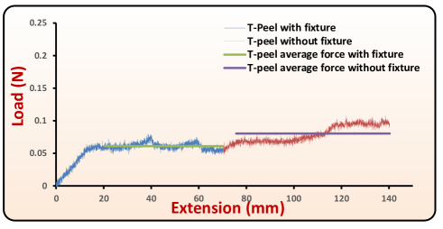
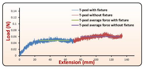
In other adhered systems, as shown in Figures 11 to 17, an increased average peel force is observed when the mechanism support is not used. For these specimens, the estimate of the overhanging length of the tail in the asymmetric-half of the test can be made from the extension (cross-head displacement) during that phase of testing.
Commonly available duct and clear cellophane tapes, Figures 11 and 12, exhibit noticeable fluctuations in the peeling force. Such fluctuations in the peeling force could be attributed to the micro-mechanisms of the fracture process itself, for example, instabilities at the crack tip, occasional slowing, and stopping of a crack shortly after the crack initiation. Even if the geometry and loading are symmetrical, and macroscopically pure opening of the interfaces is noted, yet the crack path along the inter-adhesive layer may not be in pure mode I microscopically. However, if one limits attention to a macroscopic viewpoint, then failure can be regarded as mode I.
Furthermore, inhomogeneities such as air bubbles or local unevenness in the adhered system can lead to local fluctuations in the peel forces. Weakly adhered Teflon laminates, Figures 13 and 14, exhibited a noticeable increase in average peel force when tested without the fixture. For self-adhesive vinyl laminates, Figures 15, 16, and 17, the increase in peel force, while testing without the fixture, was only marginal.
V CONCLUSION
The peel test is a popular mechanical test to measure adhesive fracture energies for flexible laminates and adopted widely. In this paper, we have analyzed the T-peel test on vertical test machines and report that effects of gravity can lead to a significant rise in experimentally measured peel forces in comparison the T-peel test where symmetry is maintained. To address the undesired effects arising due to the gravity, a mechanical fixture was developed, which can be readily adopted to different test machines. The fixture has a support plate that is kinematically coupled, through a set of racks and gears, with the cross-head of the mechanical tester. The support plate moves at half the speed of the upper cross-head, thus maintaining symmetry in the T-peel specimen and suppressing the effects of specimen weight, mixed mode failure etc. T-peel test results on several adhered systems, with and without the use of mechanical peel-fixture, demonstrate the importance of providing a symmetrical support to the specimen tail during peeling. This design thus greatly improves the performance of T-peel testing, and an accurate estimation of mode I fracture toughness (GIc). As an ongoing study, we are parametrically varying several non-dimensional quantities based on the length of overhanging tail, peak stresses in opening and shearing mode, ratio of interface toughness in mode I mode II, yield strength, modulus, density, specimen geometry, etc. to explore which factors are dominant under what conditions and identify the underlying insightful trends of the asymmetric peeling.
VI Acknowledgments
This research was supported by Novartis Pharma AG and carried out at the NVS-MIT Center for Continuous Manufacturing Laboratories.
VII Appendix
Here, we present the mechanics of the peel test, both in symmetric and asymmetric case, based on slender beam theory. The slender beam theory assumes that stresses arise due to the bending moments, and the role of axial or shear forces is negligible.
VII.1 Symmetric (ideal) T-peel
Thin (or slender) members usually demonstrate small bending stiffness, and therefore, they can undergo large deflections and rotations with only small strains. Such one-dimensional members are also referred to as an “elastica”. The first analytical solution to an elastica employing Euler-Bernouli beam bending equations was presented in Bisshopp and Drucker (1945).
Figure 18 shows the schematic of the ideal T-peel test. Here, the specimen width into the plane is considered to be large such that plane strain conditions hold.
In Figure 18, the crack tip location is marked at the location O. The upper peel arm is shown as OA, along with the forces and moments acting on it, and due to symmetry the same holds for the lower peel arm.
Adapting the elementary beam bending theory to the plane strain scenario, the relationships among strain, stress, radius of curvature, and moment are given as:
| (7) |
| (8) |
Here we assume that the elastica is inextensible. The moment equilibrium of a beam element, say at point B, implies
| (9) |
Differentiating the above equation with respect to arc length s, we get
| (10) |
Using the fact that
| (11) |
and
| (12) |
and substituting equation 11 in equation 10, we get
| (13) |
Re-arranging, we get
| (14) |
where . Now, using a substitution and integrating the above equation,
we get
| (15) |
where is the constant of integration, which can be obtained through boundary conditions on , i.e., . Now, using equations 11, 12, and 15, we can find
| (16) |
| (17) |
| (18) |
In this treatment, we have considered the unattached part as a beam whose tangent rotates from to , and thus, we have ignored base rotation effects. In general, may not be true, i.e., may not mark the onset of the unbonded part of the peel arm. The value of at the base depends on the cohesive zone extension between the two adherends Cotterell et al. (2006); Williams (1993). Although, the extent of the cohesive zone at the crack tip is problem-dependent, as long as the symmetry is maintained, the region ahead of the crack tip comprises only of normal stresses (and no shear stresses). Equations 17 and 18 also have an analytic solution when at the base Kim and Aravas (1988).
Y as well as S can grow unbounded depending on the boundary conditions. If we assume the peel arm to be long while staying within the elastic limits, then boundary conditions as per Figure 18 can be set as at or the curvature at . Thus, using equation 15, we get
Integrals in equations 16, 17, and 18, reduce to
| (19) |
| (20) |
| (21) |
Equations 19 and 21 represent improper integrals of second type, since the function to be integrated becomes unbounded in the specified limits. This implies that elastica becomes vertical only in an asymptotic sense under the absence of any moment at the upper grip. However, for practical purposes, this is attained approximately quite easily. Numerical integration can also be employed in the range [0, ) to solve for the above quantities.
Next, we calculate the elastic strain energy stored in a part of elastica from an angle of to . For any differential element
| (22) |
| (23) |
Thus, energy stored in an element of length in bending from an angle to (or attaining a curvature ) is given as follows:
| (24) |
Using equations 22 and 23, we can also write
| (25) |
Thus,
| (26) |
Consequently, the energy of the part of elastica from O up to any point on it is given as follows:
| (27) |
This can be re-written in terms of as follows:
| (28) |
For , Unet represents the total energy of the elastica. The total energy is always finite even though the length of the peel arm is unbounded. We repeat that this is true when elastica is considered to be inextensible.
Under steady-state conditions if the energy of elastica is constant (and no dissipative work occurs in the specimen), then the rate of external work equals the rate of work for interfacial de-cohesion.
| (29) |
or
| (30) |
An important aspect for experimental consideration is the length (Lunbonded) of initial unbonded part for gripping the specimen in the mechanical tester. As per Figure 18, if in the initial phase of gripping the specimen in the mechanical tester only moments act the at the clamping end A, then Mf = Mb = (say), and the unbonded part of the peel arm from A to O will form a circular quarter-arc with a constant curvature of . To avoid plastic deformation during clamping, the initial length should be chosen such that the initial radius of curvature is large enough to avoid plastic bending. The radius of curvature is
| (31) |
Plasticity is avoided by choosing such that is in the elastic limit, i.e.,
| (32) |
| (33) |
The criterion of equation 33 was employed while performing the peel tests. On the derivation of conditions for the onset of plasticity in the peel arm during bending see Kim and Aravas (1988).
VII.1.1 Role of Specimen Weight in “Symmetrical” T-peel
We wish to emphasize that in practice, although the use of the support plate leads to a symmetrical configuration visually and, largely suppresses the weight of the tail, the effect of gravity on the unsupported peel arms must be given a careful attention. Let us consider the free body diagram of the upper peel arm ‘OA’, shown in Figure 19, during symmetrical T-peel test with the gravity “turned on”.
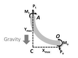
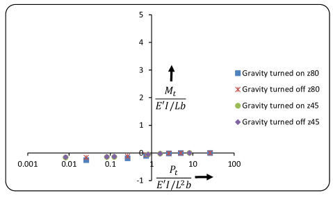
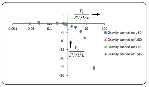
Here, is the peel force per unit width, is the moment per unit width at the upper clamping end, is the per unit width moment at the base end (which drives the opening of the crack), is the reaction force per unit width at the lower end, and and denote the maximum dimensions in and directions, respectively, with respect to the base . Let , , , and denote the length, density, thickness, plane strain modulus and moment of inertia of the peel arm , respectively. For different levels of , with equal to at the base and at the top end , we wish to evaluate the quantities , , , and with gravity “turned on”, and compare them to the ideal case with no gravity. In particular, we consider the plots of the following non-dimensionalized quantities, , , , and with respect to the applied non-dimensionalized peel force . Commercial finite element program, Abaqus Standard, was employed for this purpose.
Typically, the initial clamped lengths of the peel arms employed in our experiments were approximately – mm. During the peel test, the weight of the supported part (unpeeled portion of the specimen) is continuously transfered to (and becomes the part of) the unsupported peel arms, and therefore it is possible to sense an increase in the peel force. Thus, for illustrations we choose two representative lengths of the peel arm as mm and mm. A non-dimensional parameter is evaluated at the two lengths mm and mm, and denoted as z45 and z80, respectively. and are chosen as 1180 kg/m3 and 0.29 mm, respectively, corresponding to the case (1), as discussed in section IV. The plots of various non-dimensionalized quantities, with and without gravity, for lengths of mm (z45) and mm (z80) are shown in Figures 20- 24 222Moments are considered positive in anti-clockwise direction. Forces are considered negative in the downward direction. Summarily, it is clear that difference between the quantities, with and without the gravity, decreases as the applied peel force increases (except for the reaction force , where the difference is constant and equal to the weight of the peel arm).
In the experimental scenario corresponding to case (1), the levels of non-dimensionalized steady state peel forces were approximately 7.0-10.0 in magnitude, and from the plots presented here; it is evident that the role of the weight of the peel arm is negligible at these levels of peel forces. For other adhered systems considered in this study, non-dimensionalized steady state peel forces were noted to be much larger than 10.0 in magnitude and therefore the role of the gravity in all other cases was also negligible.
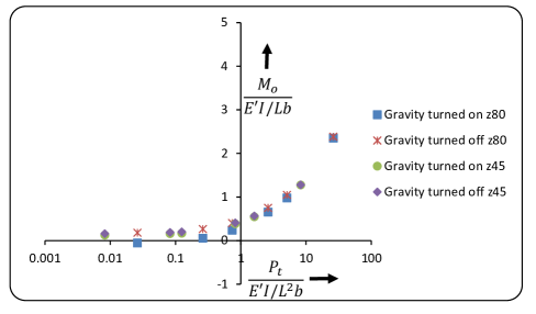
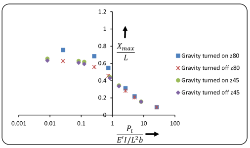
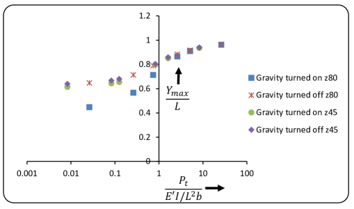
We conclude that when peel force per unit width is relatively high (up to an order of magnitude) compared to the normalizing factor for these materials, then the effect of gravity on the peel arms can be simply ignored in symmetric T-peel.
However, we wish to emphasize that although the effect of gravity on lightweight peel arms can be ignored during the symmetric peeling, it is possible that the total sample weight can be comparable to the peel forces and may contribute significantly to an increased peel force during the asymmetric peeling (when the support plate is removed). It is expected that the illustrations presented in this article should facilitate the proper accounting of different factors contributing to the peel force (and the derived fracture toughness).
VII.2 Asymmetric T-peel
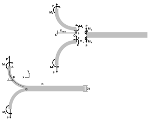
Figure 25 shows free body diagrams of the asymmetric peeling under the action of gravity.
From the global equilibrium equation, we have
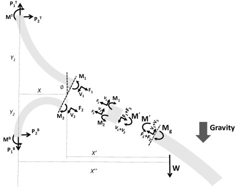
| (34) |
| (35) |
If is the moment, due to specimen weight, about the axis through the line of action of vertical forces acting at the clamp, then the total moment equilibrium can be written as follows:
| (36) |
| (37) |
If we consider the free body diagram of the upper peel arm (while ignoring its own weight), and equilibrium conditions then we have
| (38) |
| (39) |
| (40) |
Equilibrium equations for the specimen tail, of weight , imply
| (41) |
| (42) |
| (43) |
Considering the equilibrium of lower peel arm (while ignoring its own weight), we have
| (44) |
| (45) |
| (46) |
Considering the moment equilibrium of the intermediate section at the crack tip, we have
| (47) |
where, is the resultant moment due to shear and normal forces acting on the intermediate element. This implies
| (48) |
It is not necessary that the curvatures of three slender members are equal at their meeting point. Since we have only equilibrium equations for the system (two for the force balance and one for the moment balance), the system is statically indeterminate. We would need to consider compatibility, constitutive behavior, and kinematics to deterministically solve for all variables.
Based on the free body diagram shown in Figure 25, the relation between the moments and forces acting on the intermediate section and interface toughness (GIc and GIIc at the crack tip) is not straightforward. From the forces and moments acting on the intermediate element, analytical determination of crack tip stress intensities is not possible. In addition, during peeling, the equilibrium configuration for the entire system changes continuously, and therefore, deriving a correction for the associated effects is a major task requiring extensive numerical modeling. In fact, there will never be a steady state in the asymmetric case, since the degree of mode-mixity will vary with the changing length of the overhang specimen tail.
References
- (1) ASTM D903-98(2010) Standard Test Method for Peel or Stripping Strength of Adhesive Bonds .
- (2) ASTM D3807-98(2012) Standard Test Method for Strength Properties of Adhesives in Cleavage Peal by Tension Loading (Engineering Plastics-to-Engineering Plastics) .
- (3) ASTM D6252 90 Degree Peel Adhesion Equipment for Pressure-Sensitive Label Stocks .
- AST (a) ASTM D1876-08 Standard Test Method for Peel Resistance of Adhesives .
- AST (b) ASTM D3330 Standard Test Method for Peel Adhesion of Pressure Sensitive Tape .
- AST (c) ASTM D6862 Standard Test Method for 90 Degrees Peel Resistance of Adhesives .
- AST (d) ASTM F88/F88M-09 Standard Test Method for Seal Strength of Flexible Barrier Materials .
- ISO (a) ISO 11339:2010 Adhesives – T-peel test for flexible-to-flexible bonded assemblies .
- ISO (b) ISO 8510-2:2006 Adhesives – Peel test for a flexible-bonded-to-rigid test specimen assembly – Part 2: 180 degree peel .
- ISO (c) ISO 14676:1997 Adhesives – Evaluation of the effectiveness of surface treatment techniques for aluminium – Wet-peel test by floating-roller method .
- ISO (d) ISO 29862:2007 Self adhesive tapes – Determination of peel adhesion properties .
- (12) http://admet.com/products/grips-and-fixtures/peel/.
- Ins (a) http://www.instron.us/wa/acc_catalog/prod_list.aspx?cid=406&cname=Adhesive%20Peel%20Fixtures a.
- (14) http://www.mecmesin.com/peel-test-adhesion-testing.
- Spies (1953) G. Spies, Aircraft Engineering and Aerospace Technology 25, 64 (1953).
- Bikerman (1957) J. Bikerman, Journal of applied physics 28, 1484 (1957).
- Jouwersma (1960) C. Jouwersma, Journal of Polymer Science 45, 253 (1960).
- Kaelble (1959) D. Kaelble, Transactions of The Society of Rheology (1957-1977) 3, 161 (1959).
- Kaelble (1960) D. Kaelble, Transactions of The Society of Rheology (1957-1977) 4, 45 (1960).
- Yurenka (1962) S. Yurenka, Journal of Applied Polymer Science 6, 136 (1962).
- Nicholson (1977) D. Nicholson, International Journal of Fracture 13, 279 (1977).
- Kendall (1971) K. Kendall, Journal of Physics D: Applied Physics 4, 1186 (1971).
- Kendall (1973a) K. Kendall, The Journal of Adhesion 5, 179 (1973a).
- Kendall (1973b) K. Kendall, Journal of Physics D: Applied Physics 6, 1782 (1973b).
- Kendall (1975) K. Kendall, Journal of Physics D: Applied Physics 8, 1449 (1975).
- Chang (1960) F. S. Chang, Transactions of The Society of Rheology (1957-1977) 4, 75 (1960).
- Chen and Flavin (1972) W. Chen and T. Flavin, IBM Journal of Research and Development 16, 203 (1972).
- Chang, Devries, and Williams (1972) M. D. Chang, K. Devries, and M. Williams, The Journal of Adhesion 4, 221 (1972).
- Gent and Hamed (1975) A. Gent and G. Hamed, The Journal of Adhesion 7, 91 (1975).
- Gent and Hamed (1977) A. Gent and G. Hamed, Journal of Applied Polymer Science 21, 2817 (1977).
- Crocombe and Adams (1981) A. Crocombe and R. Adams, The Journal of Adhesion 12, 127 (1981).
- Crocombe and Adams (1982) A. Crocombe and R. Adams, The Journal of Adhesion 13, 241 (1982).
- Atkins and Mai (1986) A. Atkins and Y. Mai, International journal of fracture 30, 203 (1986).
- Kim and Aravas (1988) K. S. Kim and N. Aravas, International Journal of Solids and Structures 24, 417 (1988).
- Aravas, Kim, and Loukis (1989) N. Aravas, K.-S. Kim, and M. Loukis, Materials Science and Engineering: A 107, 159 (1989).
- Kim and Kim (1988) K.-S. Kim and J. Kim, Journal of Engineering Materials and Technology 110, 266 (1988).
- Kim, Kim, and Kim (1989) J. Kim, K. Kim, and Y. Kim, Journal of adhesion science and technology 3, 175 (1989).
- Kinloch, Lau, and Williams (1994) A. Kinloch, C. Lau, and J. Williams, International Journal of Fracture 66, 45 (1994).
- Wei and Hutchinson (1998) Y. Wei and J. W. Hutchinson, Interface strength, work of adhesion and plasticity in the peel test (Springer, 1998).
- Yang, Thouless, and Ward (1999) Q. Yang, M. Thouless, and S. Ward, Journal of the Mechanics and Physics of Solids 47, 1337 (1999).
- Yang, Thouless, and Ward (2000) Q. Yang, M. Thouless, and S. Ward, The Journal of Adhesion 72, 115 (2000).
- Thouless and Jensen (1992) M. D. Thouless and H. M. Jensen, The Journal of Adhesion 38, 185 (1992).
- De Lorenzis and Zavarise (2008a) L. De Lorenzis and G. Zavarise, International Journal of Solids and Structures 45, 5419 (2008a).
- Yang and Thouless (2001) Q. Yang and M. D. Thouless, International Journal of Fracture 110, 175 (2001).
- Williams and Hadavinia (2002) J. Williams and H. Hadavinia, Journal of the Mechanics and Physics of Solids 50, 809 (2002).
- Su, Wei, and Anand (2004) C. Su, Y. Wei, and L. Anand, International journal of plasticity 20, 2063 (2004).
- Zhang and Wang (2009) L. Zhang and J. Wang, International Journal of Adhesion and Adhesives 29, 217 (2009).
- Hadavinia et al. (2006) H. Hadavinia, L. Kawashita, A. Kinloch, D. Moore, and J. Williams, Engineering Fracture Mechanics 73, 2324 (2006).
- de Bruyne NA (1951) de Bruyne NA, in Adhesion and adhesives, edited by N. de Bruyne and R. Houwink (Elsevier, Oxford, 1951) p. 463–494.
- Irwin (1958) G. Irwin, in Elasticity and Plasticity, Handbuch der Physik/Encyclopedia of Physics, Vol. 3/6 (1958).
- Orowan (1945) E. Orowan, Notch, Brittleness and the Strength of Metals (Institution of Engineers and Shipbuilders in Scotland, 1945).
- Hirai et al. (2009) S. Hirai, H. Ashizawa, H. Miyagwa, S. Naito, and M. Zenichi, in 3rd Asian Conference on Adhesion, Actcity Hamamatsu, Japan (2009).
- Choi and Oh (2001) J. Choi and T. Oh, Journal of adhesion science and technology 15, 139 (2001).
- Dolah and Miyagi (2014) R. Dolah and Z. Miyagi, Journal of Testing and Evaluation ASTM 42, 50 (2014).
- (55) http://lso-inc.com/medical-package-testing/astm-f88.html.
- Ins (b) http://www.instron.us/wa/solutions/Peel_Test_Plastic_Films.aspx .
- Ins (c) http://www.instron.us/wa/solutions/Medical-Packaging-Peel-Test.aspx.
- Ins (d) http://www.instron.us/wa/solutions/peel_test_adhesives_tapes_astmd1876.aspx.
- vid (a) https://www.youtube.com/watch?v=I1SWCqNnE7c.
- vid (b) https://www.youtube.com/watch?v=K77-EPTSI-M.
- (61) A. Peterson, “Common problems with common tests,” http://www.adhesivesmag.com/articles/92564-common-problems-with-common-tests.
- Gardon (1963) J. L. Gardon, Journal of Applied Polymer Science 7, 643 (1963).
- Gent and Petrich (1969) A. Gent and R. Petrich, in Proceedings of the Royal Society of London A: Mathematical, Physical and Engineering Sciences, Vol. 310 (The Royal Society, 1969) pp. 433–448.
- Gent and Lai (1994) A. Gent and S.-M. Lai, Journal of Polymer Science Part B: Polymer Physics 32, 1543 (1994).
- Padhye et al. (2015a) N. Padhye, D. M. Parks, B. L. Trout, and A. H. Slocum, Under review (2015a).
- Suo and Hutchinson (1990) Z. Suo and J. W. Hutchinson, International Journal of Fracture 43, 1 (1990).
- Hutchinson (1990) J. W. Hutchinson, Metal and Ceramic interfaces , 295 (1990).
- El-Aguizy et al. (2005) T. El-Aguizy, J.-S. Plante, A. H. Slocum, and J. D. Vogan, Review of scientific instruments 76, 075108 (2005).
- (69) N. Padhye, Sub-Tg, Solid-State, Plasticity-Induced Bonding of Polymeric Films and Continuous Forming, Ph.D. thesis, Massachusetts Institute of Technology, Cambridge.
- Padhye et al. (2015b) N. Padhye, D. M. Parks, B. L. Trout, and A. H. Slocum, Under review (2015b).
- De Lorenzis and Zavarise (2008b) L. De Lorenzis and G. Zavarise, International Journal of Solids and Structures 45, 5419 (2008b).
- Reeder and REWS (1990) J. R. Reeder and J. H. REWS, AiAA Journal 28, 1270 (1990).
- Bisshopp and Drucker (1945) K. Bisshopp and D. Drucker, Quarterly of Applied Mathematics 3 (1945).
- Cotterell et al. (2006) B. Cotterell, K. Hbaieb, J. G. Williams, H. Hadavinia, and V. Tropsa, Mechanics of materials 38, 571 (2006).
- Williams (1993) J. Williams, The Journal of Adhesion 41, 225 (1993).
- Note (1) Moments are considered positive in anti-clockwise direction. Forces are considered negative in the downward direction.