Reduced Complexity Detection for Network-Coded Slotted ALOHA using Sphere Decoding
Abstract
Network-coded slotted ALOHA (NCSA) is a refinement to the classic slotted ALOHA protocol which improves throughput by enabling multiple source transmissions per ALOHA slot using physical-layer network coding (PNC). The receiver detects the network-coded combination of bits during every slot and recovers information bits by solving a system of linear equations. This work develops a receiver capable of detecting the network-coded combination of bits during a slot considering an arbitrary number of sources, orthogonal modulation, and a block fading channel. Maximum-likelihood detection of the network-coded symbol at the receiver becomes complex as the number of sources is increased. To reduce this complexity, sphere decoding is applied at the receiver to limit the number of constellation symbols the receiver must consider for detection. The system is simulated for two modulation orders and two through five sources, and error-rate performance results are provided.
I Introduction
Slotted ALOHA (SA) is a multiple-access protocol in which several sources transmit information to a receiver over a timespan denoted as a frame. The frame is divided into several discrete timespans denoted as slots, and sources align their packet transmission times to fall within the slots. The protocol is used in a variety of applications, such as satellite communication.
Recently, several enhancements to classical slotted ALOHA have appeared in the literature. Under the original formulation of SA reception of only one packet per slot is assumed, and reception from two or more sources in a single slot is treated as interference and discarded. All of the enhancements are based on relaxing the assumption of one packet reception per slot and allowing multiple, improving throughput. In [1], each source transmits its packet in multiple slots, deliberately causing interference, and the receiver subtracts non-interfered packets from interfered ones to recover all source packets, a process known as successive interference cancellation (SIC).
A technique has been introduced which improves the throughput of slotted ALOHA using physical-layer network coding (PNC) [2], denoted as network-coded slotted ALOHA (NCSA) [3]. Intuitively, throughput is improved by allowing more than one source to transmit a packet during a particular ALOHA slot. For a particular ALOHA frame, the sum of packets in each slot is modeled as a system of linear equations, and the receiver solves the system to recover the packets transmitted by each source. The NCSA algorithm is formulated under the assumption that the detector at the receiver can perform PNC on the packets received in each slot, but does not describe a technique for doing so.
Other works have considered the application of PNC to slotted ALOHA PNC and sphere decoding, and modulation orders for PNC beyond two. In [4], two schemes are proposed combining PNC and slotted ALOHA, one for terrestrial networks, and one for satellite networks, which require distinct control information. In [5], a lattice-based PNC scheme utilizing compute-and-forward is developed. Higher-order modulations for a system combining PNC and multiuser detection are considered by [6].
The main contribution of the current work is to develop a receiver capable of performing the PNC operation, forming a network-coded packet for each slot. Our work considers a specific modulation, -ary orthogonal modulation. Previous work has thoroughly developed a PNC receiver for frequency-shift keyed modulation under the case of relaying information between two users [7] [8], and this work extends the previous, considering an arbitrary number of users.
Detecting the network-coded packet for a particular slot requires performing detection on the sum of symbols transmitted by each source. The symbol determined by performing detection on this sum constellation is denoted as the super-symbol. In a fading environment where the channels between each source and the destination have independent fading coefficients, the number of possible super symbols is exponential in the number of sources.
Maximum likelihood (ML) detection implemented by comparing all possible super symbols to the received symbol clearly becomes intractable for increasing modulation order and number of sources. This motivates the development of a detection scheme with reduced complexity. A well-known detection technique having complexity which is independent of the constellation size is sphere decoding [9]. This work develops a sphere decoder which detects the super-symbols comprising the network-coded packets in an ALOHA slot. Detecting the transmitted super symbol enables recovery of the bits in the network-coded packet.
II System Model
In this section, the modeling assumptions used throughout the work are developed. The modulation scheme, channel model, and source and destination architectures are presented.

II-A Transmission by Source Nodes
The source nodes generate length- binary information sequences . Let denote the set of integer indices corresponding to each orthogonal dimension, where is the modulation order. The number of bits per symbol is . The information sequences from each source are divided into sets of bits, which are passed to an -ary orthogonal modulator. The modulator maps each set of bits to an -ary symbol , where denotes the source, and denotes the -th symbol, constructing a frame.
The symbols are represented in discrete time by the set of column vectors . The column vector is length , contains a 1 at vector position , and elsewhere. The modulated frame from source is represented by the matrix of symbols , having dimensionality .
II-B Channel Model
All of the channels in the system are modeled as block-fading channels. A block is defined as a set of symbols that all experience the same fading coefficient. The duration of each block corresponds roughly to the channel coherence time. The frame transmitted by source may be partitioned into blocks according to
| (2) |
where each block is an matrix, and the values of and are chosen such that is an integer. The vector of information bits mapped to the symbols in this block is denoted as , containing bits. The channel associated with block is represented by the diagonal matrix , where , is a real-valued fading amplitude distributed Rayleigh() and is a random phase shift distributed . It is assumed that the frames transmitted by the sources are received in perfect synchronization at the destination. The block at the output of the relay receiver’s matched-filters is then
| (3) |
where is an noise matrix having elements which are i.i.d. circularly-symmetric complex Gaussian random variates.
II-C Destination Reception
The goal of the destination receiver is to detect the network-coded sum of bits transmitted by the sources
| (4) |
where the sum is taken modulo-2. The elements of vector are then
| (5) |
where is the exclusive-or operation. The network-coded bits experiencing the -th fading block are denoted as , containing bits.
Consider a single symbol transmission period. The constellation formed by the sum of all possible combinations of symbols which can be transmitted by the sources is denoted as the super-symbol constellation and is defined as
| (6) |
Under orthogonal modulation, the cardinality of this constellation is . The network-coded bits represented by each super-symbol are defined as
| (7) |
where the mapping selects the -th bit mapped to the symbol, , and .
The receiver performs detection on a frame of channel observations one observation at a time. A single observation is represented by a single column of and is denoted as . The operations performed on every channel observation are the same, thus, dependence on a particular symbol interval is dropped. A channel observation is comprised of the sum of symbols transmitted by the sources during a single symbol interval.
A conventional demodulator performs detection by computing the conditional probability of receiving every possible super-symbol , an exhaustive computation which grows exponentially in the number of sources [8]. Sphere decoding reduces the number of required computations by determining a list of candidate super-symbols which fall within a specified radius from the received channel observation. Details of the sphere decoder are provided in Section III.
The symbol probabilities are transformed to the set of log-likelihood ratios (LLRs) associated with each network-coded bit mapped to a particular super-symbol. Denote this operation as digital network-coded soft mapping (DNC-SOMAP) [8]. To detect the network-coded bits, a hard decision is made on each LLR. The LLR of the -th network-coded bit mapped to the super-symbol is computed as
| (8) |
where , and are the -th and -th network-coded bits mapped to super-symbol , and is the a-priori LLR of network-coded bit which may be fed back from soft-output channel decoder. This work considers hard-decision decoding, so all . The max-star operator is defined as
| (9) |
where the binary max-star operator is and multiple arguments imply a recursive relationship; for example: .
The value taken by the pdf is dependent on the available channel state information. In this work it is assumed that the destination has perfect knowledge of the channel gains and noise variance
| (10) |
III List Sphere Decoder
The goal of the list sphere decoder (LSD) [9] is to determine the set of super-symbols which fall within a specified distance from the channel observation. Specifically, the LSD searches for super-symbols satisfying the following relation
| (11) |
where denotes the conjugate transpose operation, and is the radius from the received channel observation . Knowledge of the fading coefficients between each source and the destination is used to construct the set of constellation points which fall within the specified radius.
The efficiency of the sphere decoder algorithm is based on recursively computing Eq. (11) as the summation
| (12) |
where the subscripts and denote the -th and -th components of vectors and . The term yields
| (13) |
To efficiently compute whether a super-symbol in the received constellation falls within the specified radius from the channel observation, a parametric description of the constellation is required. Recall that the modulation scheme is modeled using an -dimensional complex vector. Since each vector component is complex valued, each may be regarded as a two-dimensional vector space having in-phase and quadrature components. The LSD recursively detects the set of in-phase and quadrature components within each vector component which fall within to form the list of received points.
Note that the -th component of takes the following value in the absence of noise
| (14) |
where is the -th component of the symbol transmitted by source . Recall that takes value if the -th source transmitted in the -th dimension and otherwise. It follows that will take one of values during a single symbol period, drawn from the sums of all possible subsets of .
Consider the -th vector component formed from the sum of a particular subset of . The component may be expressed as , where denotes a subset of . Denote the -component of as . Then Eq. (13) may be expressed as
| (15) |
rearranging
| (16) |
Define the right-hand side of Eq. (16) as
| (17) |
The value of determines whether constellation component falls within the radius as
| (18) |
Thus, the super-symbol is not within the radius when is greater than , always within the radius when is less than , and conditionally within the radius when falls between and . An example is shown in Fig. 2.

For terms Eq. (12) becomes
| (19) |
where the terms and are
| (20) | ||||
| (21) |
where is the constellation component selected at the previous -th dimension. The terms and can be efficiently accumulated during computation of every -th term of (12).
The algorithm proceeds as follows. Beginning with , the constellation components which fall with the radius are computed for all , and one is selected. The value of is decremented by , constellation components are computed for the new , and a single component is selected once again. If a value is reached where no points are found, the algorithm backtracks by adding to and selecting the next available constellation component.
Once is reached, a super-symbol is selected and its distance from the received point is computed. If the list is not full, the point is added to the list. If the list is full, the distance for the new point is compared to the longest in the list. If the new super-symbol distance is shorter than the last in the list, the new super-symbol is added to the list, replacing the previous longest point.
The algorithm terminates when distances are computed for all super-symbols falling within the radius.
IV Simulation Results
This section presents simulation results. The system described in Section II is simulated via the Monte Carlo method for several values of modulation order and number of sources. All signal-to-noise ratio values are expressed in terms of energy-per-bit ().
The sources are simulated using the following parameters. The number of sources considered is . The information sequence length is . The orthogonal modulation orders are , having bits per symbol, respectively. The number of symbols per frame is under and under . During a single frame transmission, a uniformly random information sequence is generated for each source and modulated to produce frames .
The frames are passed through the channel and corrupted. The block size considered throughout is , which was selected to reduce the required simulation time, as every block requires exhaustively computing the values of the fading coefficient described by Eq. (14). The frames are corrupted by the fading coefficients, added, and corrupted by noise according to Eq. (3).
For every symbol period in the frame, the sphere decoding algorithm is applied to limit the number of super-symbols required for computation by the DNC-SOMAP. The size of the candidate list is set to . The sphere radius is set in proportion to the noise variance , where is a constant. It was discovered through experimentation that enabled successful decoding in all cases. The sphere decoding algorithm described in Section III is applied to all symbol periods in the received frame, and the value is computed for every candidate super-symbol in all according to Eq. (10).
The values of are passed to the DNC-SOMAP to compute the LLRs of the network-coded bits for the frame using the relationship described by Eq. (II-C). The network-coded bits comprising a single frame are computed by making a hard decision on the LLRs. The a-priori LLRs to the DNC-SOMAP are set to for all simulations.
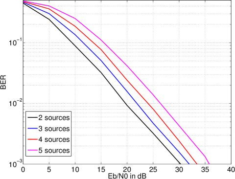
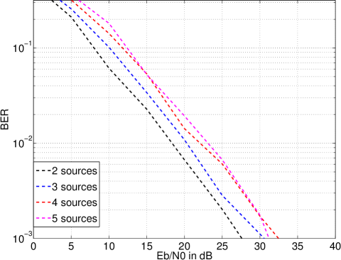
Figs. 3 and 4 show error-rate performance for modulation orders and , respectively. Considering , performance degrades by approximately for every source added to the system at error rate . Case appears to exhibit similar behavior, as the difference in performance between the best and worst performing curves are similar to the case. The curves in the case are not as smooth as , suggesting that more Monte Carlo trials are required to reduce variance.
V Conclusion
This work has developed and demonstrated a sphere decoder formulation for detecting the network-coded combination of bits transmitted by an arbitrary number of sources. The system has been developed assuming orthogonal modulation and a block fading channel. Simulation results demonstrate that the error-rate performance of the system degrades in proportion to the number of sources.
Several open issues remain. Sphere decoding in the considered system requires calculating all possible combinations of fading coefficients, which requires computations. A more efficient approach is necessary for the sphere decoder formulation to be practically efficient. The value of the sphere decoding radius was set in proportion to the channel noise variance, however, more efficiency may be obtained by reducing the radius size.
REFERENCES
- [1] E. Paolini, G. Liva, and M. Chiani, “Coded slotted aloha: A graph-based method for uncoordinated multiple access,” IEEE Trans. Inform. Theory, vol. 61, no. 12, pp. 6815–6832, Dec. 2015.
- [2] S. Zhang, S. C. Liew, and P. P. Lam, “Physical-layer network coding,” Proc. MobiComm, pp. 358–365, 2006.
- [3] S. Yang, Y. Chen, S. C. Liew, and L. You, “Coding for network-coded slotted aloha,” February 2015. [Online]. Available: http://arxiv.org/abs/1502.03903
- [4] G. Cocco, C. Ibars, D. Gündüz, and O. del Rio Herrero, “Collision resolution in slotted aloha with multi-user physical-layer network coding,” Proc. IEEE Veh. Technol. Conf., May 2011.
- [5] A. Mejri and G. R.-B. Othman, “Map decoder for physical-layer network coding using lattice sphere decoding,” Proc. Int. Conf. Telecommun., June 2014.
- [6] H. Pan, L. Lu, and S. C. Liew, “Network-coded multiple access with higher-order modulations,” 2015. [Online]. Available: http://arxiv.org/abs/1504.03426
- [7] M. C. Valenti, D. Torrieri, and T. Ferrett, “Noncoherent physical-layer network coding with FSK modulation: Relay receiver design issues,” IEEE Trans. Commun., vol. 59, no. 9, Sept. 2011.
- [8] T. Ferrett, M. C. Valenti, and D. Torrieri, “An iterative noncoherent relay receiver for the two-way relay channel,” Proc. IEEE Int. Conf. on Commun., June 2013.
- [9] B. M. Hochwald and S. ten Brink, “Achieving near-capacity on a multiple-antenna channel,” IEEE Trans. Commun., vol. 51, no. 3, pp. 389–399, 2003.