Three-dimensional photonic Dirac points stabilized by point group symmetry
Abstract
We discover a pair of stable 3D Dirac points, 3D photonic analog of graphene, in all-dielectric photonic crystals using structures commensurate with nano-fabrication for visible-frequency photonic applications. The Dirac points carry nontrivial topology and emerge for a large range of material parameters in hollow cylinder hexagonal photonic crystals. From Kramers theorem and group theory, we find that only the symmetry lead to point group symmetry stabilized Dirac points in 3D all-dielectric photonic crystals. The Dirac points are characterized using theory for photonic bands in combination with symmetry analysis. Breaking inversion symmetry splites the Dirac points into Weyl points. The physical properties and experimental consequences of Dirac points are also studied. The Dirac points are found to be robust against parameter tuning and weak disorders.
pacs:
42.70.Qs,78.67.Pt,03.65.VfI Introduction
Theoretical predictions and experimental discoveries of quantum (spin) Hall effect and Weyl points (WPs) in photonic crystals (PCs) stimulated the study of topological properties of photonic systems as well as their applications.haldane1 ; taylor1 ; mit1 ; mit2 ; austine ; ling1 ; ling-exp ; rev ; nori For example, WPs induce unique surface states with chiral isofrequency contourling1 ; ct-exp ; szhang and strongly modify photon polarization when light is reflected by the surface of a medium with WPs.szhang
Unlike WPs that exist only in systems with broken time-reversal symmetry (TRS) or inversion symmetry (IS), 3D Dirac points (DPs) exist in systems with concurrent TRS and IS.zhong1 ; zhong2 3D topological DPs, have attracted marked research interest recentlyzhong1 ; zhong2 ; chen ; furusaki ; nagaosa ; ong ; cfang as they exhibit a wide variety of anomalous effects (even not shared with WPs) such as linear quantum magnetoresistance,ong quantum spin Hall effect,zhong1 and strong diamagnetism.zhong1 DPs are important also because they are parent states of various topological states. For example, gap formation in DPs can lead to topological insulators.zhong1 ; nagaosa ; kane ; hu ; ling2
A DP consists of a pair of WPs with opposite chirality (i.e., a DP is a four-fold degenerate point around which the effective Hamiltonian resembles that of the famous Dirac equation), which is usually unstable as the two WPs can annihilate each other and form a gap. It was found only recently that a pair of DPs become stable with certain point group symmetry.zhong1 ; nagaosa In electronic systems a DP consists of two-fold spin degeneracy and two-fold accidental orbital degeneracy.
In photonic systems, however, due to the fundamental distinction of Kramers theorem for fermions and bosons (i.e., for fermions with being time-reversal operation induces double degeneracy, whereas for bosons lack such degeneracy), there is no spin- (polarization-) degeneracy. It was pointed out in Ref. lumh, that the electromagnetic duality symmetry of the Maxwell equation can be exploited to generate the two-fold polarization degeneracy since the duality transformation ; satisfies . However, such a scheme requires bianisotropic medium with which is difficult to achieve particularly for optical frequencies. In all-dielectric 3D PCs which explicitly break electromagnetic duality symmetrylumh (since ), spin- (polarization-) degeneracy of photon without fine-tuning is unlikely.book For instance, there are only two-fold degeneracy for the point (and another two-fold degeneracy for the point) for photonic graphene with both TRS and IS. In comparison there are four-fold degeneracy for the point (and another four-fold degeneracy for the point) for electronic graphene. The distinction is due to the absence of Kramers double degeneracy (i.e., spin-degeneracy) in photonic systems. A 3D photonic DP hence requires four-fold orbital degeneracy. It is unclear whether such accidental degeneracy is stable against perturbations. Moreover, designing topological states in all-dielectric photonic crystals is much more difficult than in electronic band materials due to the nature of photonic bands: they are mainly formed by multiple coherent scatteringsajeev ; eli rather than local atomic orbits.
In this work, we discover a pair of DPs with equal frequency (i.e., in total eight-fold degeneracy at such frequency) in all-dielectric PCs whose structure is commensurate with nano-fabrications for visible-frequency applications. Such paired DPs, as genuine analog of 3D photonic graphene, have never been found or studied in the literature of photonics, although the study of Weyl points and other topological phenomena in photonics has attracted a lot of attention. Remarkably, the DPs carry nontrivial topology and are stable in a large material-parameter region. We show that is the only point group symmetry that can stabilize the paired DPs in 3D PCs. Here the paired DPs are distinct from unpaired DPs locating at high-symmetry points of the Brillouin zone due to fine-tuned parameters2dmat or nonsymmorphic symmetriesling2 or Dirac-like points with three-fold degeneracy.zim3d As 3D photonic analog of graphene, the DPs can be exploited for various graphene applications such as Klein tunnelingklein and suppressed back-scattering which will be useful for robust signal transmission. Since genuine photonic devices are 3D systems,pnas 3D photonic DPs are superior for applications than their 2D counterparts.2dg1 ; 2dg2 ; 2dg3 ; zim The paired DPs can also be exploited as parent states to design other photonic topological states, such as 3D topological insulators of light. We interpret the DPs as accidental but unavoidable degeneracy points between the - and -like photonic bands, establishing an “atomic orbits” picture using Mie resonances for the design of topological states in photonics. Our study provides effective methodology beside the discovery of 3D DPs in photonic systems.
II Hexagonal photonic crystals with symmetry
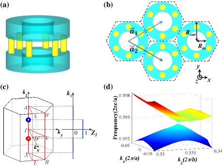
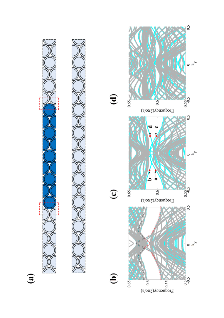
The hexagonal PC consists of hollow cylinders (with inner and outer radii and , respectively) connected by micropillars [Figs. 1(a)–1(b)]. The height of each unit cell is with being the lattice constant in the - plane. The micropillars are of the same height and diameter . There are six micropillars in each unit cell with arrangement preserving symmetry. The height of each hollow cylinder is . The Brillouin zone and high-symmetry points are depicted in Fig. 1(c). A pair of DPs emerge at . The DPs carry nontrivial topology: They are kinks of the number vs. [Fig. 1(c)]. A topological number is associated with each kink, which is defined as the change of number across the kink (with increasing ). The DPs are actually monopoles of the Berry-flux. They are quite different from the Weyl points in photonic crystalsling1 ; ct-exp ; szhang which are monopoles of the Berry-flux and have a topological charge. Our work is the first proposal of the topological Dirac points in photonic crystals.
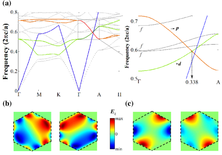
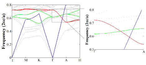
Topological DPs appear in pairs: each pair consists of two DPs of opposite ( can only be since can only be 0 or 1), wavevector but the same frequency [Fig. 1(c)]. The linear dispersion around a DP is shown in Fig. 1(d). A survey of photonic bands in the first Brillouin zone is shown in Fig. 2(a). Using permittivity for dielectric materials and and , our calculation [using MIT photonic bands (MPB)] gives . The frequency of the DPs is about (above the light-line).
Here DPs originate from accidental crossing of the and bands [Fig. 2(a)]. Such crossing is unavoidable if the order of the and bands in frequency are switched at the and points. Usually the bands have lower frequency than the bands. The inversion of the and bands results in quantum spin Hall effect () for each with (see Appendix A).hu The double degeneracy of the and bands along the - line is guaranteed by the symmetrysakoda [their field profiles at point are shown in Figs. 2(b) and 2(c)]. Interestingly, the polarization of the and bands are mostly -like. This property is consistent with the picture that Mie resonances of hollow cylinders can be regarded as photonic “atomic orbits” from which photonic bands are derived.soukoulis Indeed, in hollow cylinders the frequency of Mie resonances for TM polarization is lower than for TE (see Appendix B). We note that the DPs along the - line exist even when the micropillars are removed. In this situation, however, another DP emerges at the and point (see Appendix C).
Due to the complexity of photonic energy bands, up till now the design of topological properties in photonic crystals remains accidental and challenging particularly for three-dimensional photonic crystals. This is due to the essential difference between electronic and photonic energy bands: The photonic energy bands are consequences of multiple Bragg scattering of the vectorial electromagnetic waves as no dielectric material can trap lightsajeev ; eli ; book . In contrast, electronic band structure can mostly be understood as hybridization of local atomic orbits. For materials with inversion symmetry, the topological index can be calculated simply by counting band (parity) inversion at high symmetry points in the Brillioun zone. Such a simplified picture is not available in photonic crystals, creating lots of obstacles in designing and understanding the topological properties of photonic bands.
Our design is based on that the Mie resonances of hollow cylinders can be regarded as photonic local orbits. The photonic energy bands can be understood as derived from photon hopping between Mie resonances in neighboring unit cellssoukoulis (except for the lowest two photonic bands which also consist of the plane-wave component, see Appendix B). The hollow cylinder supports - and -wave Mie resonances with double degeneracy as protected by the and inversion symmetriessakoda ; hu . Exploiting such double degeneracy a pseudo-time-reversal operation with can be defined where is the pseudo-spin Pauli matrixhu (the double degenerate Hilbert space is defined as the pseudo-spin). This degeneracy property has been exploited to construct 2D photonic topological insulators recentlyhu . In our hollow cylinder photonic crystals the - and -like bands can be viewed as derived from the - and -wave Mie resonances. A pair of accidental but unavoidable degeneracy points of the - and - photonic bands are discovered, which are identified as the topological DPs. The degeneracy of the - and - bands comes from space group symmetry rather than the spin (polarization) degree of freedom of photon. The topological property of those photonic bands is the same as that of the energy bands in spinless bosonic systems.
III Photonic Hamiltonian and point group symmetry analysis
Near each point the doubly degenerate bands, and , can be reorganized into the pseudo-spin-up and spin-down states (similarly for the bands).hu Using symmetry and analysis [see Appendix A],sakoda the photonic Hamiltonian near the DPs () is constructed as
| (1) |
where is the frequency of the DP, and with and being the group velocity of the and bands at , respectively. , and is the group velocity in the - plane. has eigenvalue 1 (-1) for the () band, whereas . is the Pauli matrix for pseudo-spin. The photonic spectrum ( labeling the band index) is related to the eigenvalue of the Hamiltonian via . For , the above Hamiltonian resembles that of the quantum spin Hall insulator (),bhz otherwise the band topology is trivial (). Eq. (1) represents a class of massless Dirac Hamiltonian.
Since fine-tuned four-fold degeneracy’s at particular high-symmetry points are unstable, we consider DPs located on a symmetric line in the Brillouin zone which has a point group symmetry (a subgroup of the symmetry group of the PC). Such point group symmetry can be rotation along the symmetric line or mirror with respect to a plane containing the line. From group theory, only (or ) group contains two doubly-degenerate representations, which may allow four-fold accidental degeneracy.sakodabook Therefore, point group symmetry stabilized DPs can only appear in hexagonal PCs with (or ) symmetry. There are two possible cases that fulfill such requirements: DPs on the - line, and DPs on the - line (combined with - line to restore the symmetry). For both cases, detailed analysis reveals that the point group symmetry governs the form of Hamiltonian and guarantees topology of the DPs (see Appendix D). Therefore, among all point group symmetry, only and can stabilize the DPs. This property of photonic bands is in sharp contrast with electronic bands where several classes of point group symmetry (including , , and ) can stabilize the DPs.nagaosa The essential difference is that there is no two-fold spin degeneracy of photon in all-dielectric PCs, due to its bosonic nature and due to the breakdown of duality symmetry.
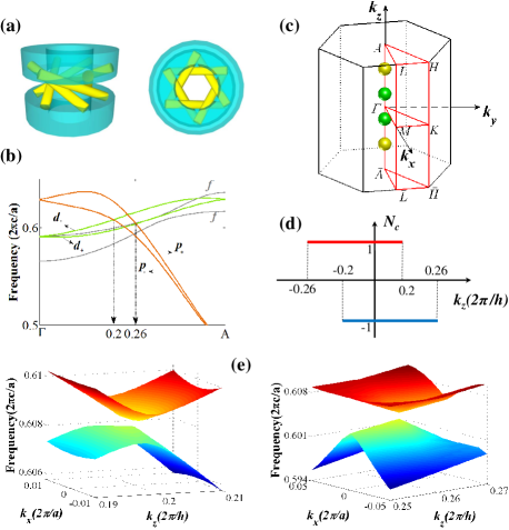
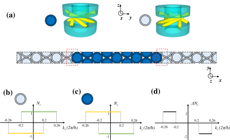
An IS breaking mechanism is introduced by twisting the micropillars and extending their heights to [Fig. 3(a)]. The degeneracy between the and bands as well as that for the and bands are now lifted [Fig. 3(b)]. However, since the symmetry is kept, the coupling between those bands remain the same form as in (1). The symmetry guarantees that those four bands can cross each other, since they have different eigenvalues. Therefore, the IS breaking mechanism only introduces the following perturbation
| (2) |
where , and are small parameters. The DPs are split into four WPs [Fig. 3(c)] with unique topology [Fig. 3(d)]: The Chern number of the pseudo-spin-up (-down) bands below the WP is -1 (1) for between () and (). The total Chern number is nonzero only for . This special distribution of Chern number is a signature of topological DPs. This unique property also influences the chiral surface states induced by the WPs as shown in the Appendix E. There we show that chiral surface states can appear at the boundary between two IS broken photonic crystal with opposite chirality. The chiral surface states can be observed in experiments to verify our predictions here. The dependent one-way edge states at such boundaries can be exploited for non-reciprocal waveguides. Recently, photonic edge states are exploited for protected quantum-entanglement propagationqe1 ; qe2 .
The spectrum of the two WPs with is shown in Fig. 3(e). The spectrum for are related with that for via the TRS. For example, state with wavevector has the same frequency as state with wavevector . The WPs connected by TRS are of the same chirality.
IV Physical consequences and robustness of Dirac and Weyl points
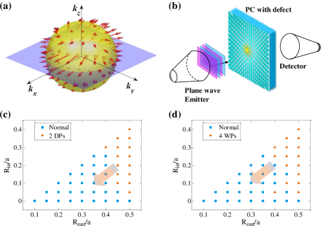
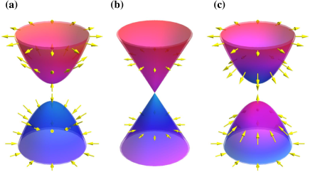
One salient feature of a DP is the angular-momentum(AM)–wavevector locking:zhong1 ; zhong2 ; chen ; ong around the DP the direction of AM is uniquely determined by the wavevector. Note that away from the DP the doubly degenerate bands have opposite AM according to concurrent TRS and IS. To visualize the AM-wavevector locking, one needs to break, e.g., IS. In Fig. 4(a) we plot the distribution of AM on a sphere surrounding the WP at (0,0,-0.2) for the IS broken PC studied in Fig. 3. The correlation between the AM and the wavevector is clearly visible. The winding geometry of AM on the sphere convinces the chirality of the WP. When the radius of the sphere is small enough () the AM distribution does not vary with the radius. Such winding angle of AM is a topological property of the WP with chirality .
AM-wavevector locking is at the heart of various novel properties of graphene and Dirac semimetalzhong1 ; zhong2 ; chen ; ong such as Klein tunneling,klein pseudodiffusive transport,2dg1 ; 2dg3 suppressed back-scattering,ong and Zitterbewegung of photon.2dg2 Suppression of back-scattering can be experimentally verified via the transmission measurement illustrated in Fig. 4(b). A small defect embedded in the PC may deflect the incident light depending on its symmetry. If the defect preserves the symmetry, then scattering is suppressed. In comparison, a defect with or symmetry can mix all of the four nearly degenerate modes around the DP and break down the protection from back-scattering. The above phenomenon can be used as another experimental signature (via comparing the transmission contrast) of the DPs.
The field profiles can also be exploited to identify the topological WPs in the IS-broken photonic crystals [see Appendix F]. We found that the Poynting vector exhibits spatial distributions similar to the skyrmion configuration. The winding direction of the Poynting vector coincides with the direction of orbital angular momentum (i.e., along direction).
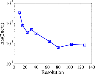
To study the robustness of the DPs and WPs, we calculate the phase diagram of the hexagonal PCs with various inner and outer radii for both PCs with and without IS. The results are shown in Figs. 4(c) and 4(d). We find that a pair of DPs emerge for a large range of parameters, indicating robustness of the DPs. In fact, the DPs can only be annihilated or created at the or point, which is the physical origin of their robustness. Since WPs are derived from the DPs, they are also robust and emerge in a large region of material parameters. Arrows in Figs. 4(c) and 4(d) indicate the tendency that the DPs or WPs move toward the point when the outer or inner radius is reduced [see Appendix G]. The DPs are also robust to weak disorders such as fabrication errors, as discussed in Appendix H. We simulated the fabrication resolution with the finite spatial resolution in computation via MPB. It is found that at small spatial resolution the Dirac points are splitted. The splitting is less than 5% of for resolution greater than 16. For resolution 24, the splitting is below 1% of . These results indicate that fabrication error within 5% of the lattice constant is well sufficient to preserve the Dirac points, which can be well achieved in the state-of-art fabrication methods of photonic crystals.revphc
V Conclusion and perspectives
We proposed the first realization of topological DPs as 3D photonic analog of graphene in all-dielectric PCs. We showed that they can exist only in hexagonal PCs with symmetry. Future research efforts need to be devoted to the novel properties of 3D photonic graphene as well as its applications, though some of them are discussed in this work. At present stage several applications can be conceived: First, it can be used as effective zero-refractive-index medium without loss.zim Second, it can exploited for frequency-, angle-, wavevector- and AM- selective transmission.yao Third, the Imbert-Federov effect depends on the winding geometry of AM around the WPs as shown in Ref. hua2, . The Imbert-Federov effect will be qualitatively distinct for different WPs in our PCs. Fourth, the DPs can be used to design other photonic topological states, such as 3D topological insulators of light. Fifth, the DPs can be used as a mechanism to suppress back-scattering and enhance signal transmission length in communications.hua This mechanism will be especially valuable if a PC fiber design with DPs is invented.
We also remark that if an electronic version of our model is realized, there will be a pair of stable double Dirac points, each of which has eight-fold degeneracy (including two-fold spin degeneracy). These novel materials are discussed only very recently.kane2 Finally, we emphasize that DPs realize all those applications without breaking TRS and IS, which considerably reduces material and fabrication difficulties.
Note Added: Shortly after finalization of this work, a proposal exploiting a pair of DPs on the - line of a hexagonal PC with symmetry as the mother state toward 3D all-dielectric weak topological insulator of light was raised.kiv
Acknowledgments
We thank supports from the faculty start-up funding of Soochow University and the National Science Foundation of China for Excellent Young Scientists (grant no. 61322504). J.H.J thanks Sajeev John, Suichi Murakami and Xiao Hu for helpful discussions.
Appendix A The theory for photonic energy bands
We use the theory on the study of the photonic band structure near the - line (i.e., we consider with to be small). The eigenvalue problem in photonic band structure is to solve the following Maxwell’s equations
| (3) |
where is the band index and is the Bloch function of the magnetic field of photon. The Bloch function is normalized as with denoting the unit cell (i.e., integration in a unit cell). The Hermitian operator can be viewed as the photonic Hamiltonian.
The essential idea of the theory around the - line is to expand the Bloch wave function at with the wavefunction at which is denoted as . Using such expansion, we obtain the following Hamiltonian,
| (4) |
where is the eigen-frequency of the band at the point. The matrix element of is given by
| (5) |
We notice that the matrix element of is nonzero only when the and bands are of different parity. Moreover, the (approximate) conservation of orbital angular momentum along direction dictates that the matrix element is prominent only between bands of angular momentum difference . Therefore, the coupling between the and bands are within the same pseudo spin, that is, between and (, respectively), or between and ().
Using the symmetry properties of the , , and wavefunctions and the and operators, one can find thatsakoda ; hu . Therefore, , where and . Thus the Hamiltonian written in the basis of is
| (6) |
where is the frequency of the Dirac point and . The group velocity in the - plane is which is a function of . To the lowest nontrivial order in and , and .
The condition is satisfied only at (more rigorously, the two points are the only points where the and bands become degenerate). The topological phase transistion as a function of is illustrated in Fig. 5. For the band structure and spin configuration resembles that of a Dirac electron with negative mass. It is known that the negative mass Dirac equation describe the topological insulator in electronic system.rev1 ; rev2 For the band gap closes and a Dirac cone emerges. For the cone is gaped again where the spin configuration resembles that of a Dirac electron with positive mass.
When the six micropillars are twisted, the symmetry of the photonic crystal is reduced from to ( is the inversion along the direction). Since is broken, the spectrum for is no longer the mirror of that for . However, the TRS guarantees the degeneracy between the state and the state as well as the degeneracy between the state and the state. Since the symmetry is kept, those four bands can cross each other at , as they correspond to different eigenvalues of the operator. Therefore, along the - line the following “mass terms” are introduced (the three quantities, , , and are the “masses”) which gap out the Dirac point. Those mass constant are odd functions of due to TRS. As a consequence, the DPs are split into WPs with chirality shown in Fig. 3.
Appendix B Mie resonances in hollow cylinder and their connection with photonic energy bands
When light is scattered by dielectric object, there are geometry induced resonances which appear in the frequency dependence of the scattering cross-section. This is known as the Mie resonance. The rigorous connection between the Mie resonance and the photonic bands was systematically established by Lidorikis et al.soukoulis Inspired by the fact that the Mie resonance frequencies are related to the photonic energy bands, those authors extended the idea of the linear combination of atomic orbitals method to photonic energy bands. In their theory the Mie resonances of isolated cylinder are treated as the atomic orbitals of photonic crystals. The hybridization/transfer between neighboring localized resonances leads to the formation of the photonic band. Particularly, in a tight-binding theory, one can expand the photonic wavefunction as superposition’s of the plane wave and the Mie resonances,
| (7) |
where stands for the wavefunction of the Mie resonance at the lattice site ( is the position of the center of that lattice site), and denote the coefficient for the plane wave and the Mie resonance, respectively. The index here labels the Mie resonance, from to , , etc. is the volume of the photonic crystal. The plane wave component is nonzero only for the (i.e., the -wave case). The plane wave component is a unique feature of the photonic bands, because it dominates the photonic wavefunction in the long wave length (i.e., low frequency) limit. It has been shown by Lidorikis et al.soukoulis that the above wavefunction can be used as basis to expand the wavefunctions of the photonic energy bands. For example, the first photonic bands is plane-wave-like for small , while it gradually becomes -wave-like and mix with other resonances at large . Higher photonic bands are dominated by the Mie resonances. A solid connection between Mie scattering cross-section, resonance frequency and the scaling function of the tight-binding parameters is also established in the work of Lidorikis et al.soukoulis
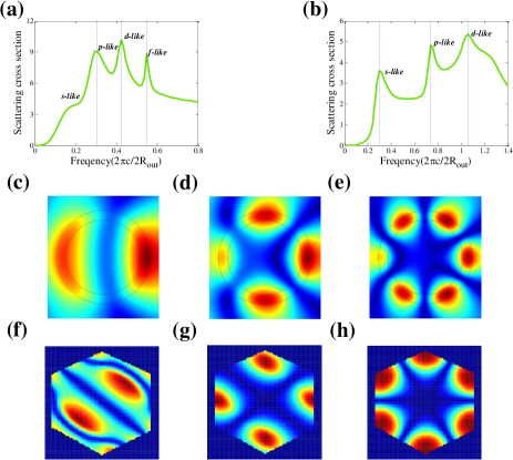
In Fig. 6a the frequency dependence of scattering cross section is shown for a hollow cylinder with outer radius 0.5 and inner radius 0.4 (the same as the hollow cylinders in our photonic crystal) for the TM polarization (calculated via COMSOL MultiPhysics). Fig. 6b gives the results for the TE polarization. In both calculation the cylinder is assumed to be infinitely long, and the photon wave vector is in the - plane. Thus, the problem considered is a two-dimensional problem.
The scattering cross-section as a function of the frequency of the incident plane wave is shown in Figs. 6a and 1b for the two situations when the incident wave is TM polarized (i.e., polarized) and when it is TE polarized (i.e., polarized), respectively. There are several peaks in the two figures which are the recognized as the Mie resonances. The electric field patterns at the resonant frequency’s are shown for the TM polarization in Figs. 6c, 1d, and 1e. The field patterns show , and -wave symmetry for the second, third, and fourth resonances for the TM polarization. We notice that the TE resonances have much higher frequency than the TM resonances. The field patterns of the TM Mie resonance is comparable with that of the , and photonic states in the hollow cylinder photonic crystal (see Figs. 6f, 1g, and 1h). The resonant frequency’s for the - and -wave scatterings for the TM polarization are and , respectively. These numbers, multiplied by the square root of the effective permittivity in our three-dimensional photonic crystal, , with ( is the permittivity for the dielectrics, e.g., silicon) being the filling ratio of silicon,soukoulis yield 0.57 and 0.8 , respectively. This rough estimation gives quite comparable results with the frequency’s of the - and - photonic bands at the point of our photonic crystal, and , respectively.
Appendix C Dirac points without micropillars
Here we show that the Dirac points exist even when the six micropillars are removed. The simplified structure is maybe more attractive for applications. The photonic bands are shown in Fig. 7. It is seen that the Dirac points also emerges as an accidental crossing of the doubly-degenerate and bands above the light-line. Meanwhile there is a Dirac point emerge on the - and - line. Although there is only two-fold degeneracy at the point from the figure, taking into account of the degeneracy at the point with the same frequency, in total it is four-fold degeneracy, i.e., a Dirac point.
Appendix D Symmetry analysis
We now analyze the constraints of the time-reversal symmetry (TRS), inversion symmetry (IS) and rotation symmetry on the photonic Hamiltonian. Let us look at the following form of a Hamiltonian,
| (8) |
where each is a matrix which is a linear combination of , , and ( is identity matrix).
First, the pseudo-time-reversal symmetry with gives rise to the following constraints, and where denotes transposition. We can thus describe the total Hamiltonian using only and . The pseudo-time-reversal symmetry can always be defined whenever there is a two-fold degeneracy.hou Ref. hu, showed how to construct the pseudo-time-reversal symmetry for the and bands in symmetric photonic crystals.
Second, the inversion symmetry is with . This imposes the further restrictions, and .
We remind the readers that in construction the pseudo-time-reversal operator and the inversion operator we have already used the properties that the four bands are the eigen-representation of the symmetry with opposite parity. Using the theory up to linear terms in , one finds that the coupling between different bands is only within each pseudo-spin. This coupling between bands with opposite parity has a winding phase in - plane in order to conserve the angular momentum along direction.fang ; nagaosa Hence, up to linear terms in ,
| (9) | |||
| (10) |
where , , and are even functions of . The sign depends on the definition of the pseudo-spin.
According to Ref. nagaosa, , the symmetry can also stabilize Dirac points the off-diagonal terms in is of the form . Such coupling is impossible for photonic bands, because it is of the form between bands with same parity in - plane which will anti-cross at a generic point along the - line (since at such point there is only symmetry, the two doubly-degenerate bands with same parity will belong to the same representation, hence symmetry cannot prevent them from anticrossing).
Therefore, in photonic crystals the only possible Dirac points is of the same form as what we discussed in the main text. The other possible case is for the Dirac points on the - line. The simplest way to understand this is that by enlarging the unit cell in real space, the - line folds back to the - line.hu Therefore, the situations are similar to what was discussed in the main text.
Appendix E Topological surface states
Due to the existence of the -bands, there is no complete band gap for the hollow cylinder photonic crystal with inversion symmetry. Nevertheless, for the inversion symmetry broken photonic crystal, there is complete photonic band gap for . We calculate the edge states for the inversion symmetry broken photonic crystal using the supercell illustrated in Fig. 8(a). Two armchair boundaries are formed between two types of photonic crystals with clockwise and anticlockwise twisted micropillars. Edge states emerge at the two boundaries as governed by the band topology. According to the analysis, the Chern numbers for the and and for the and bands below the Weyl points are plotted in Fig. 8 for the two twisted-micropillar structures. For the clockwise-twisting structure, the Chern numbers are shown in Fig. 8(b). For the anticlockwise-twisting structure, the dispersion of the - bands are switched with the - bands. Thus, for both the and regions, the position of the Weyl point with positive chirality switches with the position of the Weyl point with negative chirality. This modifies the -dependence of the Chern number [see Fig. 8(c)]. The difference of the total Chern number between the two types of photonic crystals, , is plotted in Fig. 8(d) as a function of . The two types of photonic crystals have perfectly matched photonic band gap which is suitable for the calculation of the edge states.
We calculate the edge states for , and for a supercell with 9 periods of clockwise-twisting structures and 11 periods of anti-clockwise-twisting structures along the direction [see Fig. 9(a)]. According to Fig. 8(c), the Chern number difference is zero for and , while for . To carefully take into account of the finite size effect in the supercell calculation (as the band gap can be very small here), we plot the photonic spectrum for the heterostructure (blue) together with the spectrum for the supercell with the same size but with only the anti-clockwise-twisting structures (gray) [The two kinds of supercell are illustrated in Fig. 9(a)]. Since the supercell with only the anti-clockwise-twisting photonic crystal has no boundary, its spectrum acts as a good reference for the bulk photonic spectrum with the finite size effect included.
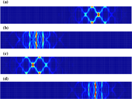
In Fig. 9(b) the blue and gray (with gray on top) spectra are almost identical. Although the finite size effect closes the band gap near , the results show that there is no edge states for . Note that the dispersion near is not due to edge states. We have checked the projected bulk photonic bands [red and black points in Fig. 9(b) for the upper and lower band edges, respectively]. It is seen that the projected photonic band gap can be very small near the region. The photonic band gap actually closed for finite size supercell with a single type of photonic crystal (as depicted by the gray curves). Note that the “curves” in Figs. 9(b), 7(c) and 7(d) are actually made of (many) points from the band structure calculation using MPB. We did not connect them artificially. Fig. 9(c) clearly demonstrates the existence of edge states for in the common photonic band gap. For [Fig. 9(d)], the photonic band gap is very small, we did not notice any edge state.
To further prove the existence of edge states and study their properties for , we plot the electromagnetic energy density in the - plane for the a, b, c, and d points in the photonic spectrum in Fig. 9(c). From Fig. 10 it is seen that there are two edge states at the right-hand-side boundary, the a and d points. From the photonic spectrum in Fig. 9(c) we find that the group velocity at both the a and d points are positive [leading to two anticlockwise (from top-down view) edge modes]. Therefore, there are two one-way edge states at the boundaries for , which is in accordance with the Chern number difference given in Fig. 8(d). This simulation proves our analysis of the topology of the photonic bands based on symmetry and the theory.
Appendix F Spatial field patterns and Poynting vector profiles
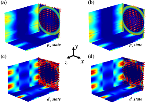
In the chiral photonic crystal (shown in Fig. 3) the four states, , , , and , can be identified via their Poynting vector profile. In Fig. 11, we plot the spatial profile of the Poynting vector (i.e., the time-averaged value ) as well as that of the electromagnetic energy density (i.e., ) on the surfaces of a block that contains a unit cell for the four photonic bands at . The spatial patterns of the Poynting vector are plotted in the - plane in Fig. 11. It is noted that the Poynting vector exhibits spatial distributions similar to skyrmion configuration. In such skyrmion configuration the Poynting vector winds around the axis. The winding direction is the same as the pseudo-spin direction, revealing the finite orbital angular momentum of the four states. In addition, the Poynting vectors at the center point along whereas at the boundaries they point along . Such flip of the Poynting vector, alongside with the winding texture comprises the full skyrmion configuration. We remark that those special field profiles can be used to identify topological photonic bands in chiral photonic crystals.
In each figure, on the three boundary planes (i.e., the -, -, and - planes) we plot the energy density by color. The red color represents high energy density, while the blue denote low energy density. For example, the energy density distribution in the - plane has a ring pattern for states (the ring coincides with the cross-section of the hollow cylinder). From the figures we notice that the electromagnetic energy is mostly localized on the cylinder for both and bands. However, the energy density profile for the bands is more anisotropic and dispersed away from the cylinder.
Appendix G Moving and Annihilating of Dirac point
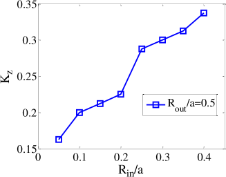
Here we show the moving of the Dirac points when the inner radius of the hollow cylinder is significantly changed, to demonstrate the robustness of the Dirac points in our photonic crystal. In Fig. 12, we plot the position of the Dirac point as a function of the inner radius of the hollow cylinder at fixed outer raidus . The two curves represent the case with . It is clearly seen that decreases with decreasing . At very small the Dirac points are moved to the point and annihilated there. This confirms that the Dirac points can only be created and annihilated in pairs, and demonstrates the robustness of the Dirac points.
Appendix H Robustness against weak disorders
In this section we study the robustness of the Dirac points against disorder effects such as fabrication errors. We use MPB to calculate the photonic band structure. In MPB the Maxwell equation is solved via real space grid method. The space resolution (i.e., how many grid points for the distance of the lattice constant ) in MPB calculation is a natural way to simulate the space resolution in fabrication. We calculate the splitting of the Dirac points (i.e., the largest frequency minus the smallest one) vs. the simulation resolution and plot the results in Fig. 13. From the figure we find that the splitting of the Dirac points is smaller than 5% of the frequency at the Dirac point for resolution greater than 16. For resolution 24, the splitting is below 1% of the frequency at the Dirac point. These results indicate that fabrication error within 5% of the lattice constant is sufficient to preserve the Dirac points, which can be well achieved in the state-of-art fabrication methods of photonic crystals.revphc
References
- (1) F. D. M. Haldane and S. Raghu, Phys. Rev. Lett. 100, 013904 (2008).
- (2) Z. Wang, Y. D. Chong, J. D. Joannopoulos, and M. Soljačić, Phys. Rev. Lett. 100, 013905 (2008).
- (3) Z. Wang, Y. Chong, J. D. Joannopoulos, and M. Soljačić, Nature (London) 461, 772 (2009).
- (4) M. Hafezi, S. Mittal, J. Fan, A. Migdall, and J. Taylor, Nat. Photon. 7, 1001 (2013).
- (5) A. B. Khanikaev, S. H. Mousavi, W.-K. Tse, M. Kargarian, A. H. MacDonald, and G. Shvets, Nat. Mater. 12, 233 (2013).
- (6) L. Lu, L. Fu, J. D. Joannopoulos, and M. Soljačić, Nat. Photon. 7, 294 (2013).
- (7) L. Lu, Z. Wang, D. Ye, L. Ran, L. Fu, J. D. Joannopoulos, and M. Soljačić, Science 349, 622 (2015).
- (8) L. Lu, J. D. Joannopoulos, and M. Soljačić, Nat. Photon. 8, 821 (2014).
- (9) K. Y. Bliokh, D. Smirnova, and F. Nori, Science 348, 1448 (2015).
- (10) W. Gao, B. Yang, M. Lawrence, F. Fang, B. Béri, and S. Zhang, arXiv:1511.04875
- (11) W.-J. Chen, M. Xiao, and C. T. Chan, arXiv:1512.04681
- (12) Z. Wang, Y. Sun, X.-Q. Chen, C. Franchini, G. Xu, H. Weng, X. Dai, and Z. Fang, Phys. Rev. B 85, 195320 (2012).
- (13) Z. Wang, H. Weng, Q. Wu, X. Dai, and Z. Fang, Phys. Rev. B 88, 125427 (2013).
- (14) Z. K. Liu et al., Science 343, 864 (2014).
- (15) T. Morimoto and A. Furusaki, Phys. Rev. B 89, 235127 (2014).
- (16) B.-J. Yang and N. Nagaosa, Nat. Comm. 5, 4898 (2014).
- (17) T. Liang, Q. Gibson, M. N. Ali, M. Liu, R. J. Cava, and N. P. Ong, Nat. Mater. 14, 280 (2015).
- (18) C. Fang, L. Lu, J. Liu, and L. Fu, arXiv:1512.01552
- (19) C. L. Kane and E. J. Mele, Phys. Rev. Lett. 95, 226801 (2005).
- (20) L.-H. Wu and X. Hu, Phys. Rev. Lett. 114, 223901 (2015)
- (21) C. He, X.-C. Sun, X.-P. Liu, M.-H. Lu, Y. Chen, L. Feng, and Y.-F. Chen, arXiv:1405.2869
- (22) J. D. Joannopoulos, S. G. Johnson, J. N. Winn, and R. D. Meade, Photonic crystals: molding the flow of light (Princeton university press, 2011).
- (23) S. John, Phys. Rev. Lett. 58, 2486 (1987).
- (24) E. Yablonovitch, Phys. Rev. Lett. 58, 2059 (1987).
- (25) J. Bravo-Abad, L. Lu, L. Fu, H. Buljan, and M. Soljačić, 2D Mater., 2, 034013 (2015).
- (26) L. Lu, C. Fang, L. Fu, S. G. Johnson, J. D. Joannopoulos, and M. Soljačić, Nat. Phys. 12, 337 (2016).
- (27) K. Sakoda, Opt. Express 20, 3898 (2012).
- (28) A. Fang, Z. Q. Zhang, S. G. Louie, and C. T. Chan, Phys. Rev. B 93, 035422 (2016).
- (29) J. Bravo-Abad, J. D. Joannopoulos, and M. Soljačić, Proc. Natl. Acad. Sci. (USA) 109, 9761 (2012).
- (30) R. A. Sepkhanov, Ya. B. Bazaliy, and C. W. J. Beenakker, Phys. Rev. A 75, 063813 (2007).
- (31) X. Zhang, Phys. Rev. Lett. 100, 113903 (2008).
- (32) S. R. Zandbergen and M. J. A. de Dood, Phys. Rev. Lett. 104, 043903 (2010).
- (33) X. Q. Huang, Y. Lai, Z. H. Hang, H. H. Zheng, and C. T. Chan, Nat. Mater. 10, 682 (2011).
- (34) K. Sakoda, J. Opt. Soc. Am. B 29, 2770 (2012).
- (35) E. Lidorikis, M. M. Sigalas, E. N. Economou, and C. M. Soukoulis, Phys. Rev. Lett. 81, 1405 (1998).
- (36) B. A. Bernevig, T. A. Hughes, and S.-C. Zhang, Science 314, 1757 (2006).
- (37) K. Sakoda, Optical Properties of Photonic Crystals (Springer, 2004).
- (38) M. C. Rechtsman, Y. Lumer, Y. Plotnik, A. Perez-Leija, A. Szameit, and M. Segev, arXiv:1605.02053
- (39) S. Mittal, V. V. Orre, and M. Hafezi, arXiv:1605.04894
- (40) S. Noda, M. Fujita, and T. Asano, Nat. Photon. 1, 449 (2007); H. Sekoguchi, Y. Takahashi, T. Asano, and S. Noda Opt. Exp. 22, 916-924 (2014); K. Ishizaki, M. Koumura, K. Suzuki, K. Gondaira, and S. Noda, Nat. Photon. 7, 133–137 (2013).
- (41) L. Wang, S.-K. Jian, and Hong Yao, arXiv:1511.09282
- (42) Q.-D. Jiang, H. Jiang, H. Liu, Q.-F. Sun, and X. C. Xie, Phys. Rev. Lett. 115, 156602 (2015).
- (43) Q.-D. Jiang, H. Jiang, H. Liu, Q.-F. Sun, and X. C. Xie, arXiv:1601.07297
- (44) B. J. Wieder, Y. Kim, A. M. Rappe, and C. L. Kane, Phys. Rev. Lett. 116, 186402 (2016).
- (45) A. Slobozhanyuk, S. H. Mousavi, X. Ni, D. Smirnova, Y. S. Kivshar, and A. B. Khanikaev, arXiv:1602.00049
- (46) K. Sakoda, J. Opt. Soc. Am. B 29, 2770 (2012).
- (47) M. Z. Hasan and C. L. Kane, Rev. Mod. Phys. 82, 3045 (2010).
- (48) X.-L. Qi and S.-C. Zhang, Rev. Mod. Phys. 83, 1057 (2011).
- (49) J.-M. Hou and W. Chen, arXiv:1507.02024
- (50) C. Fang, M. J. Gilbert, X. Dai, and B. A. Bernevig, Phys. Rev. Lett. 108, 266802 (2012).