A strongly-coupled -type micromechanical system
Abstract
We study a classical -type three-level system based on three high- micromechanical beam resonators embedded in a gradient electric field. By modulating the strength of the field at the difference frequency between adjacent beam modes, we realize strong dynamic two-mode coupling, via the dielectric force. Driving adjacent pairs simultaneously, we observe the formation of a purely mechanical ‘dark’ state and an all-phononic analog of coherent population trapping — signatures of strong three-mode coupling. The -type micromechanical system is a natural extention of previously demonstrated ‘two-level’ micromechanical systems and offers new perspectives on the architecture of all-phononic micromechanical circuits and arrays.
The ability to control phonon transport in micromechanical systems has important consequences for applications such as low-power mechanical filters, switches, routers, memories, and logic gates Trigo et al. (2002); Maldovan (2013); Habraken et al. (2012); Schmidt et al. (2012); Safavi-Naeini and Painter (2011); Zhu et al. (2007); Mahboob and Yamaguchi (2008); Hatanaka et al. (2014); Sklan (2015). As a basic starting point, considerable effort has been aimed towards achieving tunable coupling between two modes of a micromechanical resonator, using a combination of piezoelectric Okamoto et al. (2013); Mahboob et al. (2012), photothermal Ohta et al. (2015); Liu et al. (2015), and dielectric Unterreithmeier et al. (2009) forces. Realization of strong coupling — that is, coherent energy exchange between two modes at a rate () larger than their mechanical dissipation () — has recently enabled classical analogs of ‘two-level system’ coherent control, including Rabi flops, Ramsey fringes and Hahn echo Okamoto et al. (2013); Faust et al. (2013). These demonstrations provide a dress rehearsal for phonon transport in future micromechanical circuits and arrays Truitt et al. (2007); Bargatin et al. (2012).
In this Letter, we demonstrate strong coupling between three radiofrequency micromechanical resonators forming a classical analog of a -type three-level system (two nearly degenerate, low energy levels and single high energy level). The inclusion of a third ‘level’ opens the door to a rich variety of physics not accessible to two-level systems, such as analogs of EIT (electromagnetically induced transparency Harris (2008)) and CPT (coherent population trapping Arimondo (2006)). To our knowledge, a fully micromechanical -type system has not been previously implemented. By contrast, V-type three-level systems formed by a pair of optical cavity modes coupled to a common mechanical resonator mode have been extensively explored in the context of cavity optomechanics Weis et al. (2010); Dong et al. (2012); Wang and Clerk (2012a), enabling demonstrations of optomechanical state transfer Weis et al. (2010) and optomechanical dark states Dong et al. (2012). In analogy to the latter, we show that by driving both pairs of the -system micromechanical system simultaneously, destructive interference leads to the formation of a mechanical dark state and a phononic analog of CPT.
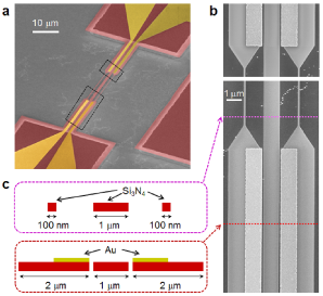
The micromechanical system, shown in Fig. 1, consists of a planar stack of three high-stress Si3N4 microbeams. The outer left and right beams possess fundamental out-of-plane flexural modes with frequencies MHz and MHz, respectively. The middle beam has a fundamental mode frequency of MHz. To couple these modes, a voltage is applied between two electrodes patterned on the outer beams. The resulting electric field produces a dielectric potential, which, owing to the spatial dependence of the field, gives rise to a static intermodal coupling Faust et al. (2013), analogous to the strain-mediated coupling of two beams sharing a non-rigid anchor Okamoto et al. (2013). We wish to emphasize that, contrary to the latter case, dielectric intermode coupling can be switched completely off by grounding the electrodes. In this sense, the mechanical modes may be considered to reside on three physically isolated mechanical resonators. Though conceptually the same as three modes of a single resonator, physical separation is advantageous for building micromechanical circuits/arrays, as it enables the resonators to be fictionalized for independent purposes. For instance, we envision that the central beam in Fig. 1 may be integrated into the a near-field of an optical cavity Wilson et al. (2015), for precision readout and actuation.
Applying a DC voltage produces static coupling between the beams; however, energy transfer between vibrational modes remains weak because of their different eigenfrequencies. To overcome this non-degeneracy, an AC voltage may be applied at the difference frequency between modes of adjacent beams. The resulting modulated static coupling strength (see Eq. 1) leads to energy flow between the two modes — hereafter referred to as dynamic intermode coupling. The magnitude of the dynamic coupling rate is proportional to the product of the AC voltage, the DC voltage, and a geometric factor proportional to the cross derivative of the dielectric potential. When sufficiently large, the dynamically coupled modes exhibit normal mode splitting. The magnitude of this splitting corresponds to their coupling rate. In our system, owing to the high room temperature quality factor of the tensily stressed beams , the normal mode splitting can be made much larger than that of mechanical dissipation (i.e. energy decay) rate, corresponding to “strong coupling”.
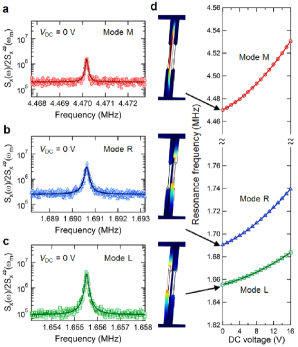
Experimental characterization of the device is shown in Fig. 2. Mechanical spectra are recorded used a lensed fiber-based interferometer Azak et al. (2007) with a spot size (m) large enough to simultaneously record the thermal displacement of each beam. The optical field, supplied by a 780 nm Ti:sapphire laser, is attenuated until photothermal effects are negligible. Sample and fiber are embedded in a vacuum chamber at mbar. When no voltage is applied across the electrodes, the fundamental out-of-plane modes of the middle (M), right (R), and left (L) beams reside at their natural frequencies with energy dissipation rates of Hz, Hz, and Hz, respectively, shown in descending order in Fig. 2a-c. The identity of each mode is verified by finite element simulation (using COMSOL, see Fig. 2d). When a DC voltage is applied to the electrodes, the mechanical frequencies are blue-shifted (Fig. 2d). The frequency shift is nearly quadratic, consistent with the dielectric force in a linear field gradient Unterreithmeier et al. (2009).
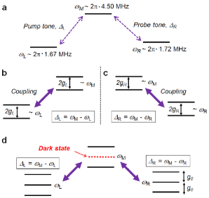
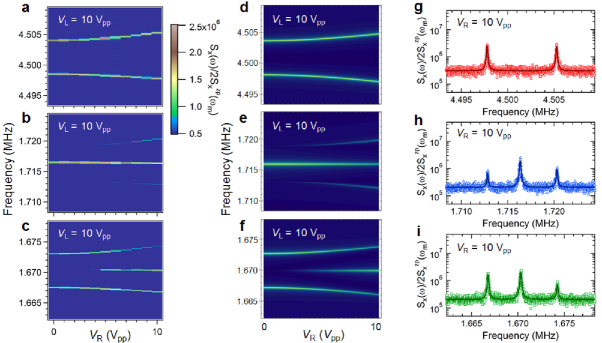
To realize dynamic intermode coupling, an AC voltage is applied across the electrodes at one of the two difference frequencies, . (Following Tian (2012); Wang and Clerk (2012b, a), we refer to these as the ‘pump’ () and ‘probe’ () tones. See Fig. 3.) For sufficiently large AC voltages, normal mode splitting is observed in the thermal displacement noise spectrum. Shown in Fig. 4 is the displacement noise spectrum plotted versus AC voltage amplitude for a fixed DC offset of V. The magnitude of the mode splitting is proportional to the AC voltage amplitude, and corresponds to twice the energy coupling rate between the left(right) and middle beam modes. Strong coupling, , is achieved for 1 in both cases. At the largest AC voltage amplitudes, the cooperativities achieved are .
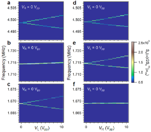
When the pump and probe tones are applied simultaneously, strong coupling is induced among all three beams. This coupling is akin to a resonant Raman interaction, and features the formation of a dynamically decoupled ‘dark’ state due to destructive interference (see Fig. 3d). To study this effect, the displacement noise spectrum is recorded versus probe strength () for a fixed pump strength of and a fixed DC offset of V. As the probe strength is increased, a trio of dressed states emerges near (Fig. 5b) and (Fig. 5c), reflecting the onset of strong dynamic coupling between all three beams. Notably, only two peaks appear near even when the three mechanical resonators are strongly coupled (Fig. 5a). The energetically allowed third peak appears ‘dark’ because of destructive interference between modes L, R, and M. This effect is analogous to coherent population trapping, as explored in optomechanical systems Wang and Clerk (2012a); Tian (2012); Wang and Clerk (2012b).
The experimental results shown in Fig. 5a-c are reproduced in Fig. 5d-f using a classical coupled-resonator model:
| (1a) | ||||
| (1b) | ||||
| (1c) | ||||
Here is the generalized displacement of the left(right,middle) beam mode, is the modulated intermode coupling rate with strength and is a generalized external force. The normal modes of Eq. 1 are: and , where . corresponds to the ‘dark’ mode, which contains no contribution from . To obtain Fig. 5d-f we solved Eq. 1 numerically using the rotating wave approximation Okamoto et al. (2013), viz., assuming
| (2) |
(and similar expressions for and ). Models in Fig. 5d-f are produced using the first-order approximation .
In summary, we have demonstrated strong dynamic coupling of three Si3N4 micromechanical resonators via dielectric forces, enabling formation of a mechanical ‘dark’ state and a classical analog of coherent phonon population trapping. It bears emphasis that experiments were performed at room temperature and that the device (included mechanical and electrical elements) is fully integrated on a chip, allowing for robust control. Pulsed switching of the gradient field is available, thus two-level control techniques (albeit here in the entirely classical analog) such as Rabi oscillation and Ramsey fringe measurements Okamoto et al. (2013); Faust et al. (2013)) and three-level techniques like pulsed EIT Tian (2012) are available. This control might be extended, for example, to nodes of micromechanical resonator circuits and arrays Truitt et al. (2007); Bargatin et al. (2012). We also remark that, by design, the three-beam system shown in Fig. 1 is readily incorporated in the evanescent near-field of a optical microdisk cavity; this platform has been shown to enable state-of-the-art interferometric displacement sensitivities as well as efficient radiation pressure force actuation Gavartin et al. (2012); Wilson et al. (2015), offering compelling opportunities for coherent coupling of electrical fields and optical fields Bagci et al. (2014); Regal and Lehnert (2011); Andrews et al. (2014); Bochmann et al. (2013).
We thank NTT for granting and supporting the sabbatical leave of H.O.. We acknowledge nanofabrication advice from M. Zervas and A. Feofanov. The sample was fabricated at the CMi (Center for Micro-Nanotechnology) at EPFL. Research was funded by an ERC Advanced Grant (QuREM), the Marie Curie Initial Training Network for Cavity Quantum Optomechanics (cQOM), and partial support from MEXT KAKENHI (Grant No. 15H05869 and 15K21727). D.J.W. acknowledges support from the European Commission through a Marie Skodowska-Curie Fellowship (IIF project 331985).
References
- Trigo et al. (2002) M. Trigo, A. Bruchhausen, A. Fainstein, B. Jusserand, and V. Thierry-Mieg, Phys. Rev. Lett. 89, 227402 (2002).
- Maldovan (2013) M. Maldovan, Nature 503, 209 (2013).
- Habraken et al. (2012) S. Habraken, K. Stannigel, M. D. Lukin, P. Zoller, and P. Rabl, New J. Phys. 14, 115004 (2012).
- Schmidt et al. (2012) M. Schmidt, M. Ludwig, and F. Marquardt, New J. Phys. 14, 125005 (2012).
- Safavi-Naeini and Painter (2011) A. H. Safavi-Naeini and O. Painter, New J. Phys. 13, 013017 (2011).
- Zhu et al. (2007) Z. Zhu, D. J. Gauthier, and R. W. Boyd, Science 318, 1748 (2007).
- Mahboob and Yamaguchi (2008) I. Mahboob and H. Yamaguchi, Nat. Nano. 3, 275 (2008).
- Hatanaka et al. (2014) D. Hatanaka, I. Mahboob, K. Onomitsu, and H. Yamaguchi, Nat. Nano. 9, 520 (2014).
- Sklan (2015) S. R. Sklan, AIP Advances 5, 053302 (2015).
- Okamoto et al. (2013) H. Okamoto, A. Gourgout, C.-Y. Chang, K. Onomitsu, I. Mahboob, E. Y. Chang, and H. Yamaguchi, Nat. Phys. 9, 480 (2013).
- Mahboob et al. (2012) I. Mahboob, K. Nishiguchi, H. Okamoto, and H. Yamaguchi, Nat. Phys. 8, 387 (2012).
- Ohta et al. (2015) R. Ohta, H. Okamoto, R. Hey, K. Friedland, and H. Yamaguchi, App. Phys. Lett. 107, 091906 (2015).
- Liu et al. (2015) C.-H. Liu, I. S. Kim, and L. J. Lauhon, Nano Lett. 15, 6727 (2015).
- Unterreithmeier et al. (2009) Q. P. Unterreithmeier, E. M. Weig, and J. P. Kotthaus, Nature 458, 1001 (2009).
- Faust et al. (2013) T. Faust, J. Rieger, M. J. Seitner, J. P. Kotthaus, and E. M. Weig, Nat. Phys. 9, 485 (2013).
- Truitt et al. (2007) P. A. Truitt, J. B. Hertzberg, C. Huang, K. L. Ekinci, and K. C. Schwab, Nano Lett. 7, 120 (2007).
- Bargatin et al. (2012) I. Bargatin, E. Myers, J. Aldridge, C. Marcoux, P. Brianceau, L. Duraffourg, E. Colinet, S. Hentz, P. Andreucci, and M. Roukes, Nano Lett. 12, 1269 (2012).
- Harris (2008) S. E. Harris, Phys. Today 50, 36 (2008).
- Arimondo (2006) E. Arimondo, “Coherent population trapping in laser spectroscopy,” in Progress in Optics XXXV (Elsevier Science, 2006) pp. 257–354.
- Weis et al. (2010) S. Weis, R. Rivière, S. Deléglise, E. Gavartin, O. Arcizet, A. Schliesser, and T. J. Kippenberg, Science 330, 1520 (2010).
- Dong et al. (2012) C. Dong, V. Fiore, M. C. Kuzyk, and H. Wang, Science 338, 1609 (2012).
- Wang and Clerk (2012a) Y.-D. Wang and A. A. Clerk, Phys. Rev. Lett. 108, 153603 (2012a).
- Wilson et al. (2015) D. Wilson, V. Sudhir, N. Piro, R. Schilling, A. Ghadimi, and T. J. Kippenberg, Nature 524, 325 (2015).
- Azak et al. (2007) N. Azak, M. Shagam, D. Karabacak, K. Ekinci, D. Kim, and D. Jang, App. Phys. Lett. 91, 093112 (2007).
- Tian (2012) L. Tian, Phys. Rev. Lett. 108, 153604 (2012).
- Wang and Clerk (2012b) Y.-D. Wang and A. A. Clerk, New J. Phys. 14, 105010 (2012b).
- Gavartin et al. (2012) E. Gavartin, P. Verlot, and T. J. Kippenberg, Nat. Nano. 7, 509 (2012).
- Bagci et al. (2014) T. Bagci, A. Simonsen, S. Schmid, L. G. Villanueva, E. Zeuthen, J. Appel, J. M. Taylor, A. Sørensen, K. Usami, A. Schliesser, et al., Nature 507, 81 (2014).
- Regal and Lehnert (2011) C. Regal and K. Lehnert, in J. of Phys.: Conf. Series, Vol. 264 (IOP Publishing, 2011) p. 012025.
- Andrews et al. (2014) R. Andrews, R. Peterson, T. Purdy, K. Cicak, R. Simmonds, C. Regal, and K. Lehnert, Nat. Phys. 10, 321 (2014).
- Bochmann et al. (2013) J. Bochmann, A. Vainsencher, D. D. Awschalom, and A. N. Cleland, Nat. Phys. 9, 712 (2013).