∎
33email: bdarbois@ulg.ac.be 44institutetext: P. Laurent 55institutetext: S. Stoukatch 66institutetext: Microsys, Montefiore Institute, ULg, Liège , Belgium
Wicking through a confined micropillar array
Abstract
This study considers the spreading of a Newtonian and perfectly wetting liquid in a square array of cylindric micropillars confined between two plates. We show experimentally that the dynamics of the contact line follows a Washburn-like law which depends on the characteristics of the micropillar array (height, diameter and pitch). The presence of pillars can either enhanced or slow down the motion of the contact line. A theoretical model based on capillary and viscous forces has been developed in order to rationalize our observations. Finally, the impact of pillars on the volumic flow rate of liquid which is pumped in the microchannel is inspected.
Keywords:
Microchannel wicking micropillar array liquid impregnationIntroduction
Wicking can be defined as the spreading of a liquid in the tiny structures of a porous media due to capillary forces. The pioneer work concerning the spreading of a viscous liquid in a capillary tube is attributed to Washburn (1921). The wicking phenomenon has a large spectra of applications such as textile science (Kissa (1996)) or heat pipe design (Tien and Sun (1971)). The problem was revisited because of microelectronics components bonding (Schwiebert and Leong (1996)). One way to model the wicking process is to consider the spreading of a liquid into a micropillar array. Ishino et al (2007) studied experimentally how a wetting liquid propagates along solid surfaces decorated with a forest of micropillars. This problem leads to numerous experimental derivations (Xiao and Wang (2011); Kim et al (2011); Mai et al (2012); Spruijt et al (2015)), numerical contributions (Semprebon et al (2014)) and theoretical modelizations (Hale et al (2014a, b)). In the case of microchannels, studies have inspected the effect of surface patterned by posts or pillars on the dynamics of liquid inside the microchannel (Gamrat et al (2008); Mognetti and Yeomans (2009); Mohammadi and Floryan (2013)). Besides, the liquid spreading into a confined micropillar array is involved in various applications such as lab-on-a-chip chromatography (Op de Beeck et al (2012)), isolation of tumor cells (Nagrath et al (2007)) or flow regulation in microfluidic (Vangelooven et al (2010)). If the problem of liquid impregnation in a micropillar array with a free surface has been extensively studied Bocquet and Barrat (2007), the effect of confinement on this phenomenon is still an open question that we address in this article.
In this work we consider the case of a square array of cylindric micropillars confined between two plates. We study experimentally the spreading of a perfectly wetting liquid as a function of the pillars characteristics (height, pitch, diameter). The measurements are compared with a theoretical model based on capillary forces and viscous resistance. Finally, the consequences of this work for capillary pumping is discussed. In addition, more complex micropillars arrangements are examined such as non-square and non-uniform lattices.
1 Experiments
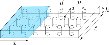
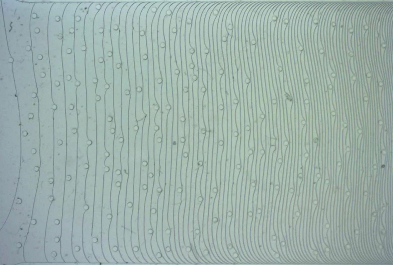
Microchannels were obtained by negative SU-8 photolithography made on a silicon wafer (Del Campo and Greiner (2007)) prior to a PDMS molding (Folch et al (1999)). The PDMS cavity was bonded on a substrate of the same material by oxygen plasma exposure. By varying the design of a the mask used in the photolithography, we changed the geometry of the micropillars array inside the channel [Fig. 1]. The channel height could be changed between and , the pillar diameter from to and the lattice pitch between and . Thus, the pillar aspect ratio may vary between 0.05 and 1.2 and the ratio between 1.5 and 10. The transverse dimension of the channel was chosen in order to keep the ratio larger than 100. These PDMS microchannels were put into contact with a liquid reservoir containing a Newtonian silicone oil V100 of density , dynamic viscosity and surface tension at a temperature . The mean position of the contact line was recorded from above and reported in Fig. 2. The analysis of these experiments provides the position of the contact line over time as shown in Fig. 3.
(a) 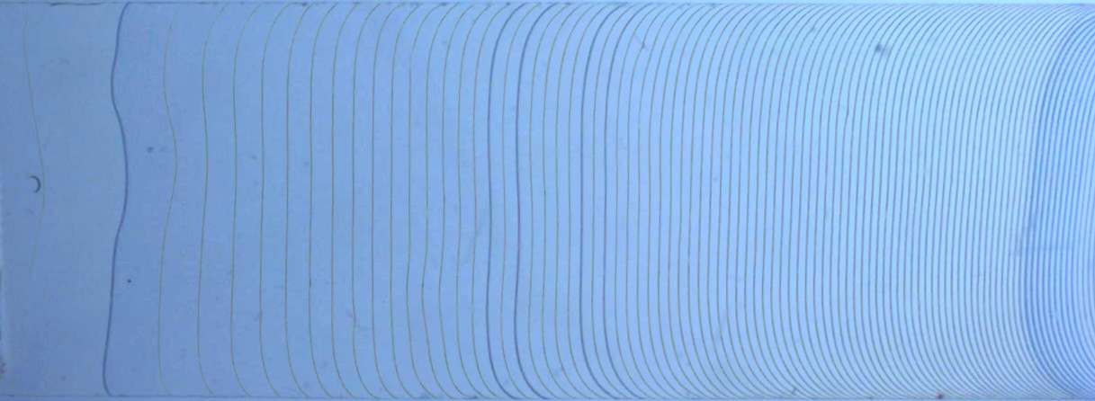
(b) 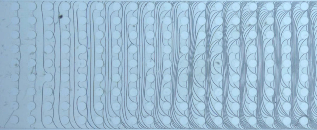
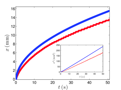
One observes that, whatever the considered microchannel, the mean position of the contact line propagates according to the square root of time. This dependency is underlined by the linearity of with time as shown in the inset of Fig. 3 and corresponds to a Washburn-like law expected for the spreading of a viscous fluid induced by capillary forces (Washburn (1921)). Besides, one notices the influence of the pillars array on the dynamics of the contact line by a change of the pre-factor of the square root law. In the considered case, the presence of pillars in the channel slows down the liquid dynamics. Additionally, the introduction of pillars in the microchannel induces a stick-slip behavior in the dynamics of the contact line which appears by the way of steps in the red curves in Fig. 3.
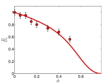
Thereafter, the effect of the micropillar array on the spreading dynamics is quantified. We measure the pre-factor of the square root law for microchannels as a function of the lattice properties (pillar diameter , height and pitch ). This pre-factor defines the diffusivity of the liquid in the micro-channel and is measured by fitting the slope of by the way of a least mean squares method. The analogous diffusivity of the liquid in the empty microchannel is denotes . Symbols in Fig. 4a and 4b show the evolution of the experimental ratio as a function of the pillar density where and are kept constants and only is varied. Two sets of experiments have been done for a different pillar aspect ratio of and and are plotted with dots.
(a)
(b)
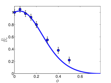
As expected, when the pillar density tends to zero, the fluid diffusivity recovers the one of an empty microchannel . In the case for which the pillars aspect ratio , the diffusivities ratio decreases monotonically with the pillar density . The situation is more complicated for the case of because the ratio first increases up to pillar density of about 0.06 and then decreases to reach values lower than unity for large pillar densities (). One remarks that in the situation where and , the presence of pillars enhances the spreading of the liquid in the channel.
2 Model
2.1 Empty cavity
The goal of this section is to develop a theoretical model in order to rationalize the experimental observations. First, we evaluate the dimensionless numbers associated to previous experiments in order to determine the main forces in presence. According to experimental data presented in Section 1, the spreading velocity reaches in less than 20 ms. This allows to estimate the Reynolds number associated to the fluid flow at this particular time: . Therefore, the liquid flow is dominated by viscous friction and no inertial terms will be taken into account in this study. The experimental Bond number, which compares the relative effect of gravity and surface tension, is . Also, we estimate the capillary number . The small value of the capillary number compared to one signifies that the contact angle remains close to its equilibrium value (Thompson and Robbins (1989)). Finally, the experimental data presented in Section 1 will be approached by a model which balances capillary and viscous forces.
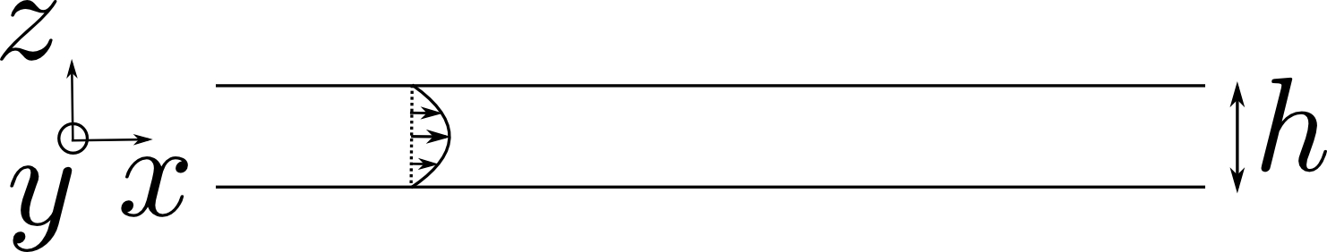
In the case where the microchannel is empty, the surface wetted by the fluid at a positon is equal to (neglecting the channel height which is more than 100 times smaller than its width ). The resulting capillary force in the direction is . The non-slipping boundary conditions of the fluid on the two microchannel plates impose a Poiseuille flow which can be expressed as: [Fig. 5a]. The flow conservation imposes . The viscous force along the -direction is equal to which provides . Balancing the capillary force with the viscous contribution provides
(a)
(b)
| (1) |
This approach predicts the square root evolution of the contact line position with time observed experimentally in Section 1 and provides a theoretical value of the diffusivity in the case of an empty microchannel. Note that, in practice this law is used to estimate the flowing time of the underfill process in microelectronics (Wan et al (2008)).
2.2 Effect of the pillar array
When the pillars are present in the microchannel, the surface of the cavity wetted by the fluid reads
| (2) |
where is the mean number of pillar rows wetted by the fluid when its interface is located in and the mean number of wetted pillar rows along the transverse direction of the microchannel. The global approach used here is justified because we consider the mean dynamics of the contact line over a distance much larger than the characteristics of the pillar array ( and ).
The resulting capillary force is
| (3) |
which reduces to
| (4) |
with the pillar density and the pillar aspect ratio.
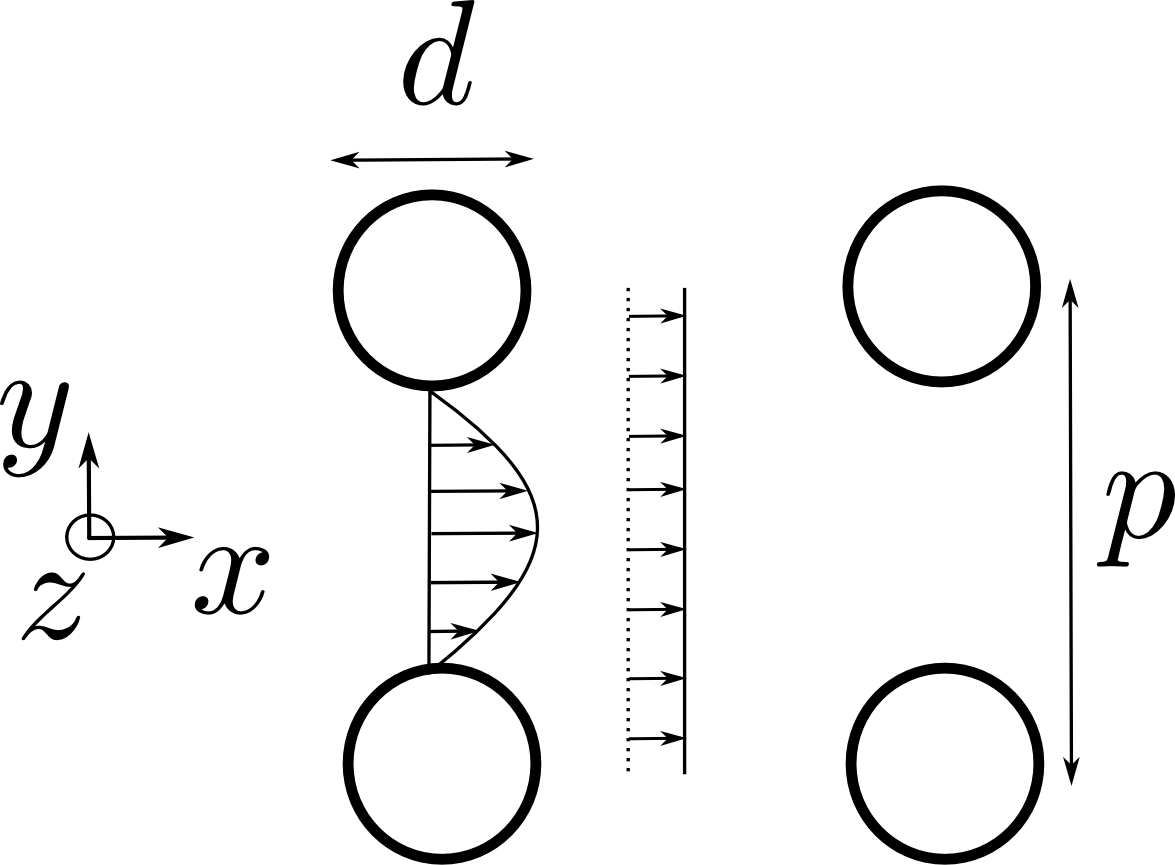
The presence of pillars inside the microchannel modifies the fluid velocity profile inside the cavity and thus the viscous force experienced by the fluid. Various studies inspected experimentally and theoretically the pressure drop resulting of a liquid flow through a square arrays of cylinders embedded inside a microchannel (Sadiq et al (1995); Tamayol and Bahrami (2009); Gunda et al (2013); Tamayol et al (2013)). However, these studies only consider the situation where the vertical confinement is negligible. In this paper, we estimate the viscous force by assuming a Poisseuille flow in the space between micropillars. We suppose that the fluid velocity profile in-between pillars is whereas the fluid velocity profile elsewhere remains [Fig. 5b]. The flow mass conservation yields and . Finally, the viscous force resulting from the fluid flow between two pillars reads
| (5) |
The total viscous force in-between pillars when the contact line is located in can be approached by
| (6) |
The previous equation yields
| (7) |
with the maximal pillar density when . The viscous contribution resulting from the fluid flow out of inter-pillar areas is
| (8) |
This equation reduced to
| (9) |
Balancing the capillary and viscous forces, , gives
| (10) |
This relation simplifies as
| (11) |
In presence of pillars, the liquid still follows a Washburn-like law () but the diffusivity now depends on the pillar array characteristics ( and ). We define the ratio of the diffusivity of the channel in presence of pillars and the diffusivity for an empty channel. This ratio is expressed as
| (12) |
2.3 Comparison with experiments
Predictions of Eq. (12) are compared with experimental data in Fig. 4 for different pillars density and various normalized pillar height by the way of solid lines. The good agreement between experiments and theoretical predictions validates the assumptions made for the profile of the flow in the model developed in section 2.2.
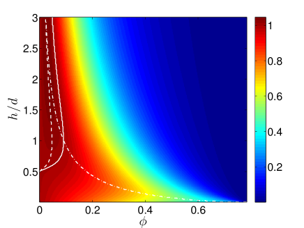
Thereafter, we consider the predictions of the model in a broader range of parameters compared to experiments. Figure 6 shows as a function the pillar density and the normalized height as predicted by Eq. (12). One notices that whatever the pillar aspect ratio, the diffusivity ratio tends to one for small pillar densities () and falls to zero for large pillar densities (). If , the diffusivity ratio is slightly larger than one for small density values () as delimited by the white solid line in Fig. 6. The analytical determination of the domain where is presented in the Appendix A. The maximal value of the diffusivity ratio increases with the normalized aspect ratio . For , reaches a maximal value of about 1.1 for . This behavior can be understood by the fact that when the liquid wets a pillar, the gain of surface energy is whereas if there was no pillar the gain of energy would have been . If , the presence of pillars increases the energetic benefit of the liquid impregnation and fasten its dynamics.
3 Discussion
3.1 Fluid pumping
In our experiments, the capillary forces pump the fluid inside the microchannel. The liquid flow rate is defined as with the volume of fluid inside the microchannel. When the contact line has the position , the volume of fluid inside the cavity is . Substituting the relation in the previous definition leads to
| (13) |
The ratio of the flow rate in a cavity with pillars and the flow rate in an empty cavity is
| (14) |
Inserting equation (12) in the previous ratio yields
| (15) |
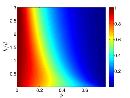
Figure 7 presents the flow rate ratio as a function of the pillar density and the pillar aspect ratio . Whatever the ratio , if the pillar density is small (), the flow rate ratio tends to one. In the opposite situation where the pillar density is large (), the ratio falls to zero. One notices that the presence of pillars only slows down the flow rate in a cavity with pillars compared to the case of an empty cavity. Thus, the addition of micro-structures in a microchannel does not enhance its pumping properties. This conclusion is of first importance for the development of capillary pumps in the context of autonomous microfluidic. In such a situation, the presence of micro-structures in the capillary pump increases its efficiency by inducing large interface curvatures which produce a large overpressure and drive the fluid (Zimmermann et al (2007)). According to our conclusions, this effect works only if the hydraulic resistance of the system is imposed by an element placed before the pump. In the context of autonomous microfluidic, the determination of the hydraulic resistance of the capillary pump compared to the one of upstream elements is essential to maximize the fluid flow rate.
3.2 Other lattices
This section aims to discuss how the conclusions drawn previously for square lattices of cylindrical pillars depend on the pillars geometry and arrangement. With the procedure described in Section 1 for microchannels fabrication, we create original pillars arrangements such as square lattices of square pillars [Fig. 8a], square lattices of cylindric pillars with defects [Fig. 8b] and randomly distributed lattices of cylindric micropillars [Fig. 8c].
(a)
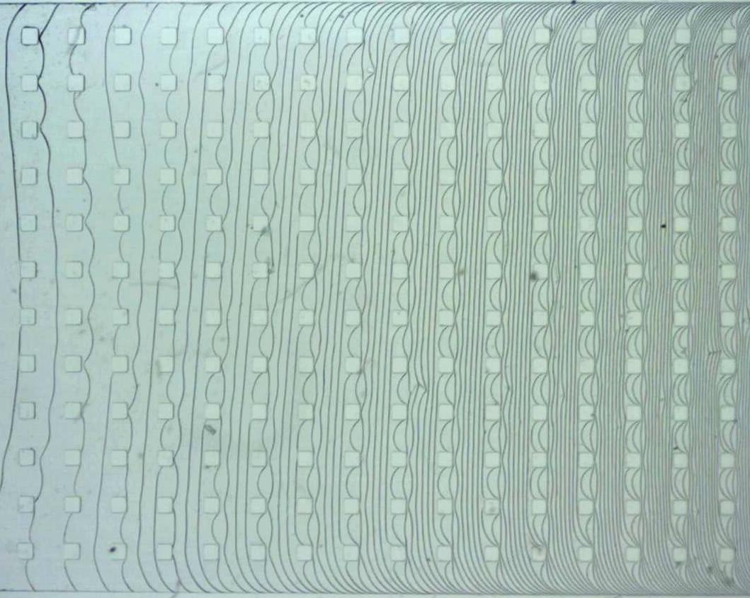
(b)
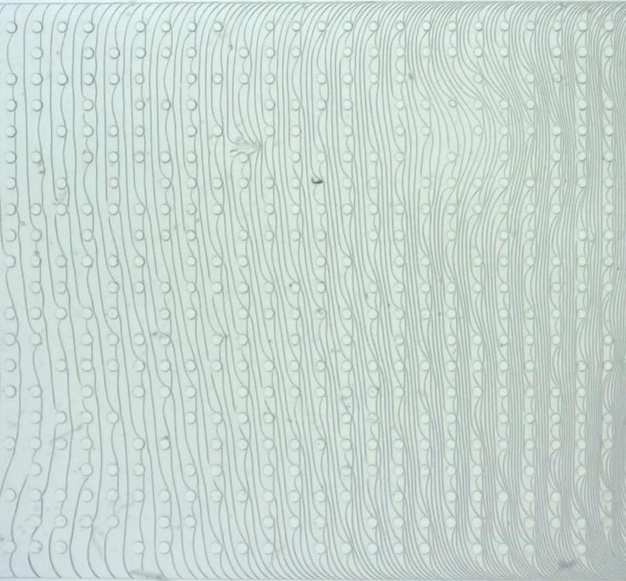
(c)
For all these cases, we recorded the wicking of a Newtonian silicone oil V100 inside the microchannels. The diffusivity coefficient was measured and compared with the one of a reference case that we choose to be a square lattice of cylindric micropillars with the same pillar density. For lattices that were non-square with cylindrical pillars, the density of pillars is defined by the ratio between the cross section of all the pillars and the total section of the microchannel. The results of these experiments are listed in Table 1.
| Lattice | |||||||
| square section pillars | 250 | 750 | 0.11 | 80 | 0.98 | ||
| square lattice of cylindric pillars with defects | 250 | 600 | 0.12 | 80 | 1.03 | ||
| random lattice of cylindric pillars | 250 | - | 0.05 | 80 | 1.02 |
First, one notices that in the three situations considered previously, the diffusivity modification induced by a change of pillar geometry or lattice arrangement are moderate. Indeed, the relative variation of the diffusivity stays below 3 % in the three situation considered above. Thus, the dynamics of the contact line in a microchannel is mainly ruled by the micro-structure density and their aspect ratio . In details, we observe that the change in the geometry of the pillars from cylindrical to square section reduces the dynamics of the liquid impregnation. The presence of defects in a square lattice of cylindric micropillars enhances slightly the fluid wicking. Finally, a random distribution of cylindric micropillars is a bit more efficient relatively to a square arrangement. Obviously, a systematic study as a function of the lattice parameters has to be lead in order to conclude on the precise impact of square section pillars, presence of defect or random distribution of pillars.
3.3 Model limitations
We propose in this section to discuss the limitation of the model developed in Section 2. This latter is based on a basic assumption of the fluid velocity profile in-between pillars. This velocity profile is clearly non-physical because it does not respect the non-slipping conditions of the fluid velocity along walls. In order to solve exactly the problem of the fluid flow inside a confined micropillars array, the Stokes equation has to be solved with the corresponding boundary conditions and thus the resulting viscous force can be deduced. We expect our model to be close from the exact solution in the case of low pillar densities but to be less accurate for large pillar densities where the confinement modifies the fluid flow far from the assumed profile. Such an effect may explain the discrepancy between experiments and theoretical predictions observed for large pillar densities in Fig. 4b.
Also, we assumed in Section 2.2 that the fluid flow adopts everywhere a fully developed velocity profile. The time needed for the fluid to reach such a state can be estimated. When a non-slipping boundary condition is imposed to a fluid flow, it spreads in a lateral direction according the relation: where is the kinematic viscosity of the liquid. In the case of the microchannels studied previously, the non-slipping conditions on the top and bottom walls spread in the direction according . The fully developed velocity profile is reached when which occurs for a critical traveled distance . For , , and we estimate that . As the microchannel is much longer than its height in our experiments, the assumption of a fully developed velocity profile is justified.
3.4 Comparison between open and confined micropillar arrays
The presence of a top wall modifies the liquid impregnation behavior compared to the case of an open micropillar array. Such a wall introduces two counteracting ingredients on the capillary flow: an additional surface to wet and another no-slip boundary condition. Following the same procedure as in Section 2.2 with a free boundary condition at the top, we deduce a theoretical prediction for the diffusivity in the case of an open microchannel. The ratio between the diffusivity in an open micropillar array and the diffusivity in a close one reads
| (16) |
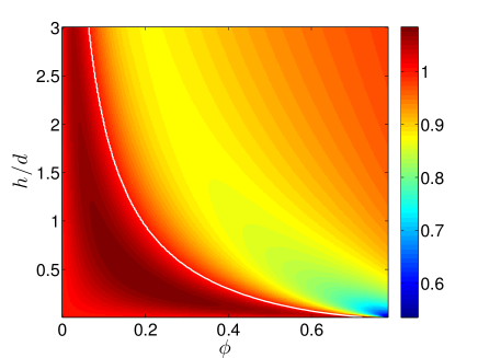
Figure 9 shows as a function the pillar density and the normalized height as predicted by Eq. (16). One notices that depending on the pillar aspect ratio and the pillar density, the diffusivity ratio is lower or larger than one. Thus, the two antagonistic effects, i.e. capillary pumping and viscous resistance, caused by the introduction of a top wall can overcome each other regarding the properties of the micropillar array. For dense arrays of slender pillars, the liquid impregnation in a confined micropillar array is faster than in a similar open array. In such situations, the confinement enhances the liquid spreading.
Conclusions
The wicking of a micropillar array confined between two plates by a perfectly wetting and viscous liquid has been investigated experimentally. We showed that the presence of pillars can either enhance or slow down the dynamics of the contact line. However, the pillars only slow down the flow rate of the liquid which penetrates into the microchannel. A model based on the estimation of capillary forces and viscous friction inside the microchannel was developed. This latter provides a fair agreement with experimental data. In the end, this study predicts the fall of the efficiency of the liquid impregnation with increasing pillar density. This result has implications for the underfill process in microelectronics packaging where the liquid filling time is a limiting factor of the production (Wan et al (2008)).
A perspective of this work is to refine the basic model proposed to describe the liquid dynamics. The exact determination of the viscous force in the microchannel can be addressed by the way of numerical simulations. Besides, this study only considers pillars with cylindrical and square section. It could be interesting to vary this shape and introduce concave geometries in order to study the effect on the liquid dynamics and the possible entrapment of air bubbles. Furthermore, this study only considers the ideal situation where the liquid perfectly wets the entire surface of the microchannel. The modification of our predictions in the case of a liquid which partially wets the solid is an open question which has to be investigated. Finally, the impact of the non-Newtonian behaviors of a liquid on its wicking dynamics through a micropillar array can also be the scoop of future studies.
Acknowledgements.
This research has been funded by the Inter-university Attraction Poles Programme (IAP 7/38 MicroMAST) initiated by the Belgian Science Policy Office. SD thanks the FNRS for financial support. We acknowledge Mathilde Reyssat, Tristan Gilet and Pierre Colinet for fruitful discussions and valuable comments. We are grateful to Stéphanie Van Loo for precious advices concerning the realization of the PDMS microchannels.Appendix A
Equation (12) allows to determine the critical pillar density in order to have with . The critical density verifies the relation
| (17) |
which has a solution only if . Equation (17) is solved numerically as a function of and the solution is indicated in Fig. 6 by a white solid line.
For , the diffusivity ratio reaches a maximal value for a pillar density which can be calculated by deriving Eq. (12) relatively to keeping constant. Such a calculation is performed numerically and the solution is indicated in Fig. 6 by a white dashed line. Finally, the pillar aspect ratio which maximizes the diffusivity ratio for a given pillar density verifies
| (18) |
References
- Op de Beeck et al (2012) Op de Beeck J, De Malsche W, Tezcan D, De Moor P, Desmet G (2012) Impact of the limitations of state-of-the-art micro-fabrication processes on the performance of pillar array columns for liquid chromatography. Journal of Chromatography A 1239:35–48
- Bocquet and Barrat (2007) Bocquet L, Barrat JL (2007) Flow boundary conditions from nano-to micro-scales. Soft matter 3(6):685–693
- Del Campo and Greiner (2007) Del Campo A, Greiner C (2007) Su-8: a photoresist for high-aspect-ratio and 3d submicron lithography. Journal of Micromechanics and Microengineering 17(6):R81
- Folch et al (1999) Folch A, Ayon A, Hurtado O, Schmidt M, Toner M (1999) Molding of deep polydimethylsiloxane microstructures for microfluidics and biological applications. Journal of Biomechanical Engineering 121(1):28–34
- Gamrat et al (2008) Gamrat G, Favre-Marinet M, Le Person S, Baviere R, Ayela F (2008) An experimental study and modelling of roughness effects on laminar flow in microchannels. Journal of Fluid Mechanics 594:399–423
- Gunda et al (2013) Gunda N, Joseph J, Tamayol A, Akbari M, Mitra S (2013) Measurement of pressure drop and flow resistance in microchannels with integrated micropillars. Microfluidics and nanofluidics 14(3-4):711–721
- Hale et al (2014a) Hale R, Bonnecaze R, Hidrovo C (2014a) Optimization of capillary flow through square micropillar arrays. International Journal of Multiphase Flow 58:39–51
- Hale et al (2014b) Hale R, Ranjan R, Hidrovo C (2014b) Capillary flow through rectangular micropillar arrays. International Journal of Heat and Mass Transfer 75:710–717
- Ishino et al (2007) Ishino C, Reyssat M, Reyssat E, Okumura K, Quere D (2007) Wicking within forests of micropillars. EPL (Europhysics Letters) 79(5):56,005
- Kim et al (2011) Kim S, Moon MW, Lee KR, Lee DY, Chang Y, Kim HY (2011) Liquid spreading on superhydrophilic micropillar arrays. Journal of Fluid Mechanics 680:477–487
- Kissa (1996) Kissa E (1996) Wetting and wicking. Textile Research Journal 66(10):660–668
- Mai et al (2012) Mai T, Lai C, Zheng H, Balasubramanian K, Leong K, Lee P, Lee C, Choi W (2012) Dynamics of wicking in silicon nanopillars fabricated with interference lithography and metal-assisted chemical etching. Langmuir 28(31):11,465–11,471
- Mognetti and Yeomans (2009) Mognetti B, Yeomans J (2009) Capillary filling in microchannels patterned by posts. Physical Review E 80(5):056,309
- Mohammadi and Floryan (2013) Mohammadi A, Floryan J (2013) Pressure losses in grooved channels. Journal of Fluid Mechanics 725:23–54
- Nagrath et al (2007) Nagrath S, Sequist LV, Maheswaran S, Bell DW, Irimia D, Ulkus L, Smith MR, Kwak EL, Digumarthy S, Muzikansky A, et al (2007) Isolation of rare circulating tumour cells in cancer patients by microchip technology. Nature 450(7173):1235–1239
- Sadiq et al (1995) Sadiq T, Advani S, Parnas R (1995) Experimental investigation of transverse flow through aligned cylinders. International Journal of Multiphase Flow 21(5):755–774
- Schwiebert and Leong (1996) Schwiebert MK, Leong WH (1996) Underfill flow as viscous flow between parallel plates driven by capillary action. Components, Packaging, and Manufacturing Technology, Part C, IEEE Transactions on 19(2):133–137
- Semprebon et al (2014) Semprebon C, Forsberg PSH, Priest C, Brinkmann M (2014) Pinning and wicking in regular pillar arrays. Soft Matter
- Spruijt et al (2015) Spruijt E, Le Guludec E, Lix C, Wagner M, Quéré D (2015) Liquid filmification from menisci. EPL (Europhysics Letters) 112(1):16,002
- Tamayol and Bahrami (2009) Tamayol A, Bahrami M (2009) Analytical determination of viscous permeability of fibrous porous media. International Journal of Heat and Mass Transfer 52(9):2407–2414
- Tamayol et al (2013) Tamayol A, Yeom J, Akbari M, Bahrami M (2013) Low reynolds number flows across ordered arrays of micro-cylinders embedded in a rectangular micro/minichannel. International Journal of Heat and Mass Transfer 58(1):420–426
- Thompson and Robbins (1989) Thompson P, Robbins M (1989) Simulations of contact-line motion: slip and the dynamic contact angle. Physical Review Letters 63(7):766
- Tien and Sun (1971) Tien C, Sun K (1971) Minimum meniscus radius of heat pipe wicking materials. International Journal of Heat and Mass Transfer 14(11):1853–1855
- Vangelooven et al (2010) Vangelooven J, De Malsche W, De Beeck JO, Eghbali H, Gardeniers H, Desmet G (2010) Design and evaluation of flow distributors for microfabricated pillar array columns. Lab on a Chip 10(3):349–356
- Wan et al (2008) Wan J, Zhang WJ, Bergstrom D (2008) Experimental verification of models for underfill flow driven by capillary forces in flip-chip packaging. Microelectronics Reliability 48(3):425–430
- Washburn (1921) Washburn EW (1921) The dynamics of capillary flow. Physical review 17(3):273
- Xiao and Wang (2011) Xiao R, Wang EN (2011) Microscale liquid dynamics and the effect on macroscale propagation in pillar arrays. Langmuir 27(17):10,360–10,364
- Zimmermann et al (2007) Zimmermann M, Schmid H, Hunziker P, Delamarche E (2007) Capillary pumps for autonomous capillary systems. Lab on a Chip 7(1):119–125