Strongly-coupled nanotube electromechanical resonators
Coupling an electromechanical resonator with carbon-nanotube quantum dots is a significant method to control both the electronic charge and the spin quantum states. By exploiting a novel micro-transfer technique, we fabricate two strongly-coupled and electrically-tunable mechanical resonators on a single carbon nanotube for the first time. The frequency of the two resonators can be individually tuned by the bottom gates, and strong coupling is observed between the charge states and phonon modes of each resonator. Furthermore, the conductance of either resonator can be nonlocally modulated by the phonon modes in the other resonator. Strong coupling is observed between the phonon modes of the two resonators, which provides an effective long distance electron-electron interaction. The generation of phonon-mediated-spin entanglement is also analyzed for the two resonators. This strongly-coupled nanotube electromechanical resonator array provides an experimental platform for studying the coherent electron-phonon interaction, the phonon mediated long-distance electron interaction, and entanglement state generation.
I Introduction
Carbon nanotubes (CNTs) Saito1998 are noted for their nearly perfect structures with nanometer diameter, ultralow mass density, great mechanical strength and elastic properties, as well as ballistic electron transport Ilani2010 ; Laird2015 . Owing to good electrical conductivity and lack of impurities and net nuclear spin, the electron charge and spin states in gate-defined CNT quantum dots (QDs) Biercuk2005 ; Sapmaz2006a ; Sapmaz2006 ; Grove-Rasmussen2008 ; Jung2013 are promising candidates for solid-state quantum information processing. However, a scalable quantum processor requires long-range couplings, which is a challenge for QDs, because there are only local interactions between neighboring QDs. Many researches have been undertaken on the development of a “quantum bus” to transfer quantum information, carried by electrons, over certain distances Petersson2012 ; Deng2015 . For example, a single electron can be conveyed between QDs over distances of micrometers Meunier2011 ; Mcneil2011 , and an integrated superconducting microwave cavity can mediate the coupling between spins over distances of millimeters Petersson2012 .
On the other hand, the excellent mechanical properties of CNTs enable their use as high frequency and high-quality-factor nanomechanical resonators Laird2012 ; Moser2014 . The vibrations of suspended CNTs can modulate the electrochemical potential of quantum dots, which leads to coherent coupling between single electron charge and phonon Steele2009 ; Lassagne2009 . Additionally, the deformation of CNTs can induce an effective transverse magnetic field applied on the electron spins that arises from the spin-orbit interaction Ando2000 ; Huertas2006 ; Kuemmeth2008 , thereby allowing spin flips by phonons Palyi2012 ; Ohm2012 . These approaches provide avenues toward the coherent operation and transduction of the quantum state of CNT QDs by a phonon, or alternatively, the electronic manipulation of the phonon quantum state Wang2014 ; Bulaev2008 ; Rudner2010 ; Benyamini2014 ; Zippilli2009 ; Meerwaldt2012 . Theoretically, mechanically-induced two-qubit gates and maximally-entangled states for two spins trapped in a single CNT have recently been studied Wang2015 . However, those previous works have only focused on the localized electron-phonon interactions. Hence, the great potential of using phonons as flying qubits for communicating electron spins over long-distance Rabl2010 ; Gustafsson2014 ; Schuetz2015 is overlooked.
Here we demonstrate a highly-tunable electrically-coupled nanomechanical resonator system of a single CNT with two suspended sections. We developed a novel transfer method, which can precisely posit the CNT to the designated location and maintain the clean surface of the CNT without requiring of chemical treatment. In the conductance spectrum, an avoided crossing indicates a strong coupling between the two CNT electromechanical resonators and the hybridization of two modes, and also proves the strong coupling between the electron charge and individual hybrid mode. To our knowledge, this is the first demonstration of non-local coupling between an electron charge and phonon in a carbon nanotube. Our theoretical study also predicts that remote-entanglement spin-state preparation is feasible in this device, for practical experimental parameters.
II Results
II.1 Experiment Setup
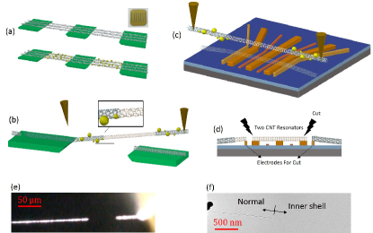
Figure 1 shows the sample fabrication method, where a CNT (typically single- or double-walled, 2-3 nm in diameter and grown by chemical vapour deposition) is suspended over two trenches (1.2 m wide, 200 nm deep) between three metal (Ti/Au) electrodes. The CNT is transferred by a novel near-field micro-manipulation method, by which the perfect clean single CNTs are deterministically and precisely posited on the electrodes, without degrading the quality of the CNT (see Fig. 1). The measurements are performed in a He3 refrigerator at a base temperature of approximately 270 mK and at pressures below torr (see Methods for details).
The suspended CNT is biased and actuated by two electrodes underneath the CNT (Fig. 2(a)). Each suspended section of the CNT simultaneously serves as both a mechanical resonator and a quantum dot. The gate voltages, , induce an average additional charge on the CNT, where is the capacitance between the -th gate and the CNT. The attraction between the charge and its opposite charge on the -th gate causes an electrostatic force downward on the CNT, leading to a mean electrostatic force on the CNT as
| (1) |
Here, is the derivative of the gate capacitance with respect to the distance between the gates and the CNT, while and are the DC bias and AC signal electric fields applied to the electrodes, respectively.
By applying a DC voltage , the nanobeam-type nanomechanical resonator can be deformed by the static force , and the induced additional tension on the CNT changes the frequencies of the mechanical resonances. In addition, the electron transport properties of the quantum dot also depend on the electrochemical potential on the dot, and so are controllable by the DC voltage. For instance, Figs. 2(b, c) show the currents through the quantum dot as a function of gate voltage. The st quantum dot is working in the Coulomb blockade regime, while the nd is working in the Fabry-Perot interference regime Liang2001 . Both quantum dots can be tuned to work in different regimes by changing the Grove-Rasmussen2007 ; Moser2014 . If an RF driving field is applied, when the frequency approaches the resonance frequency of the -th resonator, the periodic driving force will effectively actuate the mechanical vibration. The phonons can also be generated by a parametric driving force with .
II.2 Individual nanotube resonators
Before studying the coupled resonators, we first investigate the two mechanical resonators independently. Owing to the RF driving force, we obtain the driving displacement vibration , with driving frequency , amplitude of the mechanical oscillator
| (2) |
phase factor , effective mass and nonlinear Duffing term . The displacement-modulated capacitor of the suspended CNT can modify the current, which has the same effect on the modulated gate voltage as Huttel2009 ; Moser2014 . Therefore, the drain-source current changes with time as , with the shown in Fig. 2. The measured change of the DC current is approximated by
| (3) |
to second order. Figure 2 shows the measured DC current as a function of driving frequency at low temperature, for various driving powers. For relatively low driving powers, the spectra show symmetry peaks. The Duffing coefficient is measured to be of the order of . High order nonlinearities begin to exist when the driving power is larger than -40 dBm. (see the supplementary materials).
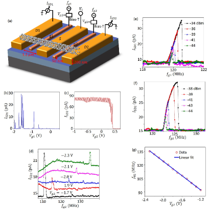
The quality factor of the resonator and resonance frequency of the CNT resonator are determined by fitting the spectrum obtained at low driving power with a Lorentzian function. The quality factors of both resonators are (largest value in our measurements), which yield an energy relaxation time of . Figs. 2(d, g) show the broadband tunability of the resonance frequency , which is linearly increased with . This can be explained as an incremental increase of the elastic tension on the nanotube, which is almost linearly proportional to the perturbative DC voltage applied to the gate. From the data for resonator 2, we fit the coefficient . This number is orders of magnitude larger than those reported for other systems, such as 2 kHz/V for tunability with capacitive forces Rugar1991 , 240 kHz/V with a Lorentz force Karabalin2009 , 40 kHz/V for piezoelectric NEMSs Mahboob2008 , and 10 kHz/V for a dielectric force setup Unterreithmeier . Such a large frequency-shifting coefficient, as demonstrated by our CNT nanomechanical device, allows us to tune the phonon modes to be on-resonance or off-resonance with each other, offering a great ability to reconfigure the phonon-electron system to regions inaccessible in other systems.
II.3 Coupled resonators
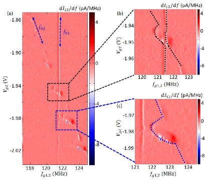
Based on the fact that the resonators are highly tunable, we can study the electron-phonon strong coupling by varying the gate field Steele2009 ; Lassagne2009 ; Meerwaldt2012 ; Moser2013 ; Benyamini2014 . Fixing V, and the corresponding resonance frequency MHz, we scan to make near-resonant with and record the current . In this case, we drive the two resonators simultaneously with two individual microwave sources at the same frequencies (43 dBm for resonator 1 and 49 dBm for resonator 2). To achieve a better resolution, we show the numerically-differentiated as a function of frequency and in Fig. 3(a). As indicated by the inclined arrow, linearly decreases with increasing , and greatly modifies the current for the bias field that yields the peaks or dips observed in Fig. 2(c). At these points, we also observed a change of mechanical resonance frequency of . Such phenomena arise from the strong phonon-electron tunneling interaction, which was firstly reported in 2009 Steele2009 ; Lassagne2009 . The fluctuation of electron charges on the CNT induces the back-action force on the mechanical modes, softening and damping the phonon modes [Fig. 3(c)]. The largest frequency shift is about , and the quality factors of the resonators are also largely reduced from 10,000 to 500 because of damping, corresponding to an increase of linewidth of phonon mode to . The frequency shift is about 3 times of magnitude larger than the linewidth of phonon mode, verifying the strong coupling of the mechanical motion and single-electron tunneling, and the damping rate induced by electron-phonon coupling kHz, showing that the mechanical motion is largely damped at these points.
In contrast to previous results, obtained for single-nanotube mechanical oscillators, our system shows an additional vertical line (corresponding to resonator 1) where the frequency does not change with . This line clearly demonstrates the influence of resonator 2 on the electron charge in resonator 1, which provides evidence of the non-local control of the electron charge by phonons. When this line encounters the photon-electron tunneling interaction frequency, as shown in Fig. 3(b), the spectrum exhibits distinct features. A magnified 2D spectrum is shown in Fig. 4(a), with a clear avoided-crossing when scanning the frequency of resonator by varying .
To quantitatively verify this phonon-phonon interaction mechanism, we also theoretically modeled the system using the Hamiltonian ()
| (4) |
where is the phonon hopping between two resonators arising from the tunneling. Therefore, the coupling induced new normal modes with hybridization of two oscillators
| (5) |
with normalization factor and eigenfrequencies
| (6) |
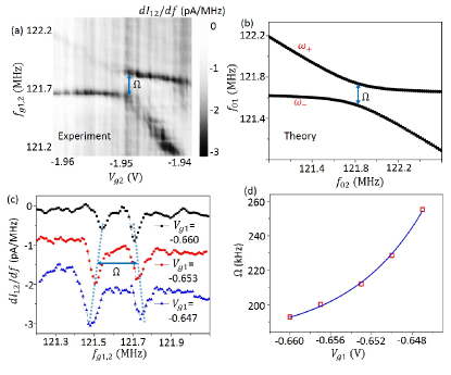
The calculated hybrid modes are shown in Fig. 4(b), by fitting the parameters from our system. The good correspondence with experiment confirms that the mechanism observed in Fig. 4(a) is coherent mechanical mode coupling. Especially, the obtained is an order of magnitude larger than . Therefore, the phonon-phonon coupling is in the strong-coupling regime , and can be used for further coherent manipulation Faust2013 .
The coherent coupling is further studied for various . As indicated by Eq. 6, the coupling strength can be extracted directly through the minimum frequency difference between the hybrid modes (). Therefore, we plotted the spectrum of the minimum frequency splitting for different biased . Note that the changes the intrinsic frequency of , thus the is adjusted to match the for each plot. Again, the two symmetrical dips in the spectrum confirm the equal superposition of and (Eq. 5) for . Intriguingly, the coupling strength shows a dependence on . This might be attributed to the increase of tension of the nanotubes with increasing , which reduces the evanescent phonon field on the S-electrode and suppresses the phonon tunneling. We find that the coupling strength can be tuned from 190 kHz to 250 kHz when is varied from V to V (Fig. 4(d)).
II.4 Phononic quantum bus and discussion
Taking advantage of our novel fabrication method, the coupled CNT mechanical resonators could be extended to one dimensional resonator arrays, where a single CNT is put on a chip with multiple suspended sections. Combined with an electrically-configurable individual mode frequency and hopping rate, phonons could be manipulated and guided along the array on demand. Our study suggests that phonons are promising for quantum bus that can be used to transfer information over distances. It is instructive to consider two possible configurations: Given double quantum dots on each suspended section, phonons can assist single-electron tunneling between the dots, as demonstrated in Fig. 3. As a result, the quantum charge state can be coherently coupled with the localized phonon. Alternatively, according to the inherent curvature and the spin-orbit interaction Bulaev2008 ; Rudner2010 ; Steele2013 , the spin states can be flipped by the phonons. Based on the phonon-phonon coupling demonstrated in this work, the excitation can be transferred between qubits over distance, and an effective qubit-qubit coupling can then be realized by the virtual collective phonon mode.
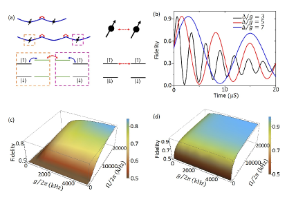
Specifically, we take the qubit as an example to illustrate the generation of spin entanglement states through the phononic quantum bus. As schematically shown in Fig. 5(a), there are two mechanical resonators each containing a single spin. More generally, such effects also hold for an array of resonators. For ideal conditions, without any dissipation or decoherence, the initial state of the system would evolve to the state , which is the maximum entangled state over a distance of the order of microns. For practical parameters, spin-phonon coupling strength Ohm2012 ; Palyi2012 (also see the supplementary materials), temperature and , the fidelity of the entanglement state for various detuning is plotted in Fig. 5(b) (see Methods for details). Owing to the trade-off between phonon relaxation and effective phonon-mediated coupling , a moderate detuning shows a longer coherence time and also maximum fidelity. In Fig. 5(c, d), the fidelity versus and is shown for mK and mK, respectively. The results indicate that both strong phonon-phonon coupling and spin-phonon coupling are important for remote-entanglement generation. Although the thermal-excitation decoherence substantially degrades the entanglement fidelity, it is still possible to observe this remote-entanglement effect in the current experiment setup ( mK) if we can increase the to kHz by decreasing the width of [Fig. 1(a)]. High-fidelity remote-entanglement generation () is promising with mK, kHz and kHz, which are parameters that can be readily realized with current technologies.
In summary, we have studied the electron-phonon coupling in strongly-coupled carbon nanotube nanomechanical resonators. Our study suggests the use of phonons as coherent quantum information carriers to mediate the effective interaction between electron spins. The engineered phonons can also be used to initialize, readout and manipulate the electron spin states. Using phonons as flying qubits is the first step in the exploration of multiple degrees-of-freedom electron-phonon systems. Possible future works would investigate CNT mechanical resonator arrays in phononic quantum memories Zhang2015 , also many-body interactions Soykal2013 and the implementation of possible quantum error correction schemes in coupled spin-phonon chains Waldherr2014 . This system can even be further integrated with superconducting circuits to construct a hybrid quantum machine Xiang2013 ; Deng2015a .
Methods
Sample preparation The CNTs were grown using the ethane CVD method on a silicon substrate with trenches. The prepared CNTs were all double- or triple-walled CNTs, with diameters ranging from 2 to 3 nm. After depositing TiO2 nanoparticles onto the suspended parts of the CNTs for visualization, the inner shell of the CNTs were drawn out and placed in their proper positions with high precision using two homemade tips under an optical microscope. The electrodes and alignment marks were fabricated on an undoped silicon chip with 500 nm oxide, by optical lithography followed by metal deposition (5 nm Ti and 45 nm Au) with an electron-beam evaporator. Two gate electrodes beneath the resonators were fabricated by electron beam lithography (EBL) followed by metal deposition (5 nm Ti and 45 nm Au). Finally, the contact electrodes (10 nm Ti and 190 nm Au) were fabricated, to decrease the residual resists as much as possible. The EBL resists used here were single-layered PMMA 950 A4 for the gates and double-layered for the contacts. After the transfer process, electrical annealing was used to improve the contact. The resistance of our devices was typically several hundred at room temperature.
Detection The driving AC signals were produced by two individual analogue signal generators (Agilent E8257D), attenuated by 30 dB at room temperature, then transmitted to the sample through Lake-Shore cables. There was an approximately 5 dB attenuation in the cable; however, we estimate a 3 dB error from sample to sample in our setup. Gate and bias DC voltages are controlled by the DC ports of a lock-in amplifier (SR830). AC and DC voltages are combined by a bias-T (Anritsu K251). Current through the resonator was measured by a multi-meter, after a pre-amplifier (SR570).
Theory of phonon mediated entanglement Considering the simple two-resonator case studied here, we obtain the system Hamiltonian as Ohm2012 ; Palyi2012 ; Wang2014
| (7) | |||||
For simplicity, we assume the phonon modes and spins are identical ( and ). In the normal mode representation, we have , whose frequencies differ by . Allowing the phonon modes to be largely detuned from the spin transitions (), therefore mediates the spin-spin interaction but rarely absorb the excitations. By adiabatic elimination of the phonon modes, the spins obey the Master equation as , where the effective Hamiltonian is
| (8) |
with and Lindbald form . Here, the pure dephasing rate is estimated from hyperfine interaction Csiszar2014 , and the intrinsic energy relaxation is neglected owing to the negligible environment phonon density of state, and the effective energy relaxation rate arising from is .
References
- 1 Saito, R., Dresselhaus, G., and Dresselhaus, M. S. Physical Properties of Carbon Nanotubes. World Scientific Publishing, (1998). ISBN 978-1-86094-093-4 (hb) ISBN 978-1-86094-223-5 (pb).
- 2 Ilani, S. and McEuen, P. L. Annu. Rev. Condens. Matter Phys. 1(1), 1–25 (2010).
- 3 Laird, E. A., Kuemmeth, F., Steele, G. A., Grove-Rasmussen, K., Nygard, J., Flensberg, K., and Kouwenhoven, L. P. Reviews Of Modern Physics 87(3), 703–764 (2015).
- 4 Biercuk, M. J., Garaj, S., Mason, N., Chow, J. M., and Marcus, C. M. Nano Lett. 5(7), 1267–1271 (2005).
- 5 Sapmaz, S., Meyer, C., Beliczynski, P., Jarillo-Herrero, P., and Kouwenhoven, L. P. Nano Lett. 6(7), 1350–1355 (2006).
- 6 Sapmaz, S., Jarillo-Herrero, P., Kouwenhoven, L. P., and Zant, H. S. J. V. D. Semicond. Sci. Technol. 21(11), S52–S63 (2006).
- 7 Grove-Rasmussen, K., Jø rgensen, H. I., Hayashi, T., Lindelof, P. E., and Fujisawa, T. Nano Lett. 8(4), 1055–1060 (2008).
- 8 Jung, M., Schindele, J., Nau, S., Weiss, M., Baumgartner, A., and Schönenberger, C. Nano Lett. 13(9), 4522–4526 (2013).
- 9 Petersson, K. D., McFaul, L. W., Schroer, M. D., Jung, M., Taylor, J. M., Houck, a. a., and Petta, J. R. Nature 490(7420), 380–383 (2012).
- 10 Deng, G. W., Wei, D., Li, S. X., Johansson, J. R., Kong, W. C., Li, H. O., Cao, G., Xiao, M., Guo, G. C., Nori, F., Jiang, H. W., and Guo, G. P. Nano Lett. 15(10), 6620–6625 (2015).
- 11 Meunier, T. and Ba, C. Nature 477(7365), 435–438 (2011).
- 12 Mcneil, R. P. G., Kataoka, M., Ford, C. J. B., Barnes, C. H. W., Anderson, D., Jones, G. A. C., Farrer, I., and Ritchie, D. A. Nature 477(7365), 439–442 (2011).
- 13 Laird, E. A., Pei, F., Tang, W., Steele, G. A., and Kouwenhoven, L. P. Nano Lett. 12(1), 193–197 (2012).
- 14 Moser, J., Eichler, A., Guttinger, J., Dykman, M. I., and Bachtold, A. Nat. Nanotechnol. 9(12), 1007–1011 (2014).
- 15 Steele, G. A., Huttel, A. K., Witkamp, B., Poot, M., Meerwaldt, H. B., Kouwenhoven, L. P., and Zant, H. S. J. v. d. Science 325(5944), 1103 (2009).
- 16 Benjamin, L., Yury, T., Jari, K., David, G.-S., and Adrain, B. Science 325, 1107 (2009).
- 17 Ando, T. J. Phys. Soc. Japan 69(6), 1757–1763 June (2000).
- 18 Huertas-Hernando, D., Guinea, F., and Brataas, A. Phys. Rev. B 74(15), 155426 (2006).
- 19 Kuemmeth, F., Ilani, S., Ralph, D. C., and McEuen, P. L. Nature 452(7186), 448–452 (2008).
- 20 Palyi, A., Struck, P. R., Rudner, M., Flensberg, K., and Burkard, G. Phys. Rev. Lett. 108(20), 206811 (2012).
- 21 Ohm, C., Stampfer, C., Splettstoesser, J., and Wegewijs, M. R. Appl. Phys. Lett. 100(14), 143103 (2012).
- 22 Wang, H. and Burkard, G. Phys. Rev. B 90(3), 035415 July (2014).
- 23 Bulaev, D. V., Trauzettel, B., and Loss, D. Phys. Rev. B 77(23), 235301 (2008).
- 24 Rudner, M. S. and Rashba, E. I. Phys. Rev. B 81(12), 125426 (2010).
- 25 Benyamini, a., Hamo, A., Kusminskiy, S. V., von Oppen, F., and Ilani, S. Nat. Phys. 10(2), 151–156 January (2014).
- 26 Zippilli, S., Morigi, G., and Bachtold, A. Phys. Rev. Lett. 102(9), 096804 mar (2009).
- 27 Meerwaldt, H. B., Labadze, G., Schneider, B. H., Taspinar, A., Blanter, Y. M., van der Zant, H. S. J., and Steele, G. A. Phys. Rev. B 86(11), 115454 (2012).
- 28 Wang, H. and Burkard, G. Phys. Rev. B 92(19), 195432 nov (2015).
- 29 Rabl, P., Kolkowitz, S. J., Koppens, F. H. L., Harris, J. G. E., Zoller, P., and Lukin, M. D. Nat. Phys. 6(8), 602–608 May (2010).
- 30 Gustafsson, M. V., Aref, T., Kockum, A. F., Ekstrom, M. K., Johansson, G., and Delsing, P. Science 346(6206), 207–211 September (2014).
- 31 Schuetz, M. J. a., Kessler, E. M., Giedke, G., Vandersypen, L. M. K., Lukin, M. D., and Cirac, J. I. Phys. Rev. X 5(3), 031031 (2015).
- 32 Liang, W., Bockrath, M., Bozovic, D., Hafner, J. H., Tinkham, M., and Park, H. Nature 411(6838), 665–669 (2001).
- 33 Grove-Rasmussen, K., Jø rgensen, H. I., and Lindelof, P. E. Phys. E Low-Dimensional Syst. Nanostructures 40(1), 92–98 (2007).
- 34 Huttel, A. K., Steele, G. a., Witkamp, B., Poot, M., Kouwenhoven, L. P., and Van Der Zant, H. S. J. Nano Lett. 9(7), 2547–2552 (2009).
- 35 Rugar, D. and Grutter, P. Phys. Rev. Lett. 67(6), 699–702 (1991).
- 36 Karabalin, R. B., Cross, M. C., and Roukes, M. L. Phys. Rev. B 79(16), 165309 apr (2009).
- 37 Mahboob, I. and Yamaguchi, H. Nature Nanotech. 3(5), 275–279 (2008).
- 38 Unterreithmeier, Q. P., Weig, E. M., and Kotthaus, J. P. Nature 458(7241), 1001–1004 (2009).
- 39 Moser, J., Guttinger, J., Eichler, A., Esplandiu, M. J., Liu, D. E., Dykman, M. I., and Bachtold, A. Nature Nanotech. 8, 493 (2013).
- 40 Faust, T., Rieger, J., Seitner, M. J., Kotthaus, J. P., and Weig, E. M. Nature Phys. 9(8), 485–488 (2013).
- 41 Steele, G. A., Pei, F., Laird, E. A., Jol, J. M., Meerwaldt, H. B., and Kouwenhoven, L. P. Nat. Commun. 4, 1573 (2013).
- 42 Zhang, X., Zou, C.-L., Zhu, N., Marquardt, F., Jiang, L., and Tang, H. X. Nat. Commun. 6, 8914 nov (2015).
- 43 Soykal, O. O. and Tahan, C. Phys. Rev. B 88(13), 134511 October (2013).
- 44 Waldherr, G., Wang, Y., Zaiser, S., Jamali, M., Schulte-Herbrüggen, T., Abe, H., Ohshima, T., Isoya, J., Du, J. F., Neumann, P., and Wrachtrup, J. Nature 506(7487), 204–7 February (2014).
- 45 Xiang, Z.-L., Ashhab, S., You, J., and Nori, F. Rev. Mod. Phys. 85(2), 623–653 apr (2013).
- 46 Deng, G.-W., Wei, D., Johansson, J. R., Zhang, M.-L., Li, S.-X., Li, H.-O., Cao, G., Xiao, M., Tu, T., Guo, G.-C., Jiang, H.-W., Nori, F., and Guo, G.-P. Phys. Rev. Lett. 115(12), 126804 sep (2015).
- 47 Csiszar, G. and Palyi, A. Phys. Rev. B 90(24), 245413 (2014).
Acknowledgment
We thank Liang Jiang, Lin Tian and Guido Burkard for beneficial discussions. This work was supported by the National Fundamental Research Program (Grant No. 2011CBA00200), the Strategic Priority Research Program of the Chinese Academy of Sciences (Grant No. XDB01030000), and the National Natural Science Foundation (Grants No. 11222438, 11174267, 61306150, 11304301, and 91421303). This work was also supported by the National Basic Research Program of China (2012CB932301), National Key Basic Research Program of China (MOST 2013CB922003) and NSF of China (No. 11474178).
Author Contribution
G.W.D. and D.Z. conceived the device. D.Z., X.H.W., K.L.J., D.L. and Y.L. fabricated the samples. G.W.D., H.O.L., G.C., G.C.G. and M.X. performed the measurements. G.W.D., D.Z. and X.H.W. analyzed the data. C.L.Z. and G.P.G. conducted the theoretical investigation. G.P.G. supervised the project. All authors contributed to the writing of this paper.
Additional information
Competing financial interest: The authors declare that they have no competing financial interests.