Phase matched backward-wave second harmonic generation in a hyperbolic carbon nanoforest
Abstract
We show that deliberately engineered spatially dispersive metamaterial slab can enable co-existence and phase matching of contra-propagating ordinary fundamental and backward second harmonic electromagnetic modes. Energy flux and phase velocity are contra-directed in backward waves which determines extraordinary nonlinear-optical propagation processes. Frequencies, phase and group velocities, as well as nanowavequide losses inherent to the electromagnetic modes supported by the metamaterial can be tailored to optimize nonlinear-optical conversion of frequencies and propagation directions of the coupled waves. Such a possibility, which is of paramount importance for nonlinear photonics, is proved with numerical model of the hyperbolic metamaterial made of carbon nanotubes standing on metal surface. Extraordinary properties of backward-wave second harmonic in the THz and IR propagating in the reflection direction are investigated with focus on pulsed regime.
pacs:
41.20.Jb, 42.25.Bs, 42.65.Ky, 42.65.Sf, 77.84.Lf, 78.67.Ch, 78.67.PtI Introduction
Metamaterials (MM) are artificially designed and engineered materials, which can have properties unattainable in nature. MM rely on advances in nanotechnology to build tiny metallic nanostructures smaller than the wavelength of light. These nanostructures modify the electromagnetic (EM) properties of MM, sometimes creating seemingly impossible optical effects. Negative-index MM (NIM) are most intriguing EM materials that support backward EM waves (BEMW). Phase velocity and energy flux (group velocity) become contra-directed in NIM. The appearance of BEMW is commonly associated with simultaneously negative electric permittivity () and magnetic permeability () at the corresponding frequencies and, consequently, to negative refractive index []. Such counter-intuitive backwardness of EMW is in strict contrast with the electrodynamics of ordinary, positive-index materials (PIM). It was generally accepted that the magnetization at optical frequencies is negligible Land and, hence, did not play any essential role. It is because natural optical emitters (atoms) are much smaller than optical wavelengths. Consequently, magnetic permeability was normally set equal to one in the basic Maxwell’s equations describing linear and NLO processes. In the late 1960s, V. G. Veselago considered propagation of EM in an fictitious, isotropic medium with simultaneously negative dielectric permittivity and magnetic permeability and showed that it would exhibit unusual EM properties Vesel1 ; Vesel2 . The situation has dramatically changed with the advent of nanotechnology. As was shown in Smith1 ; Smith11 ; Smith2 ; mu1 ; mu2 ; mu3 ; NIMExp1 ; NIMExp2 , specially shaped metallic nanostructures can enable negative optical magnetism. While the physics and applications of NIM are being explored world-wide at a rapid pace since then, current mainstream still focuses on fabricating of nanoscopic LC circuits shaped as split rings, horse shoe, fishnets, etc. that ensures negative magnetic response. Size of such mesoscopic structures (metaatoms and metamolecules) embedded in dielectric host material is typically about several tens to hundred nanometers. Since excitation of electrons (plasma) localized in nanometer-scale metallic building blocs determines the outlined extraordinary EM properties of such MM, they are commonly referred to as plasmonic metamaterials (PMM).
Backwardness of EM waves dictates a revision of many concepts concerning EM propagation processes in man-made materials. This holds the promise of revolutionary breakthroughs in microwave and photonic device technologies Sh ; MM . Such breakthrough can be employed to develop a wide variety of devices with enhanced and uncommon functions, such as enhanced photovoltaic light collection, biosensing, perfect imaging, all-optical memories and invisibility cloaks. Nanostructured NIM are expected to play a key role in the development of all-optical data processing chips. Much success has already been demonstrated at microwave frequencies. This has led to commercially available products. However, the situation is different in the optical regime, where the visionary applications are expected to have the highest and most wide-ranging impact.
Nonlinear optical photonics in NIMs holds promises of the breakthrough that essentially broaden the scope and power of the photonic applications ShC . It has been shown that opposite directions of the energy flow and phase velocity in NIM gives rise to unique NLO propagation processes KivSHG ; Sl ; APB . The possibility to compensating losses inherent to most plasmonic MM through coherent NLO energy exchange between ordinary and BEMW is among the important applications OL . Such losses present a severe formidable obstacle towards applications of NIMs. A review and corresponding references, including experimental realization, can be found in EPJD ; SPIE ; Mw ; Such ; OQE . Creation of the MM that would enable co-existence of ordinary and BEMWs at the particular frequencies, their phase matching and strong NLO response is of paramount importance, while presents a great challenge.
This paper is to study a novel paradigm for BW photonics that does not rely on optical magnetism APA2012 ; AST2013 ; SSP2014 . At that, it enables co-existence and phase matching of ordinary and backward EMWs through the alternative approach based on tailored variable quasi-hyperbolic dispersion. Such a possibility and its general implementation principles are demonstrated with numerical simulations for the particular example applicable to SHG in the THz and mid IR frequency ranges. It is shown that SHG in the proposed NIM exhibits exotic properties, especially in the pulse regime, that can be employed for unparallel applications to photonics and device technologies. Consideration of particular technique for engineering of nonlinearity is beyond the scope of this work.
The basic idea is as follows. The limitations associated with characterization of NIM by negative and and the possibility of more general approach based on spatial inhomogeneity of dielectric properties of materials at the nanoscale were described in Refs. Agr ; AgGa . The latter give rise to dispersion of the electromagnetic response of the medium to perturbations of frequency and wave vector . The presence of the spatial dispersion signifies a nonlocal dielectric response. It is manifested by the dependence of the generalized dielectric tensor on the wavevector and may lead to difference in signs of phase and group velocities. In a loss-free medium, energy flux and directed along group velocity which may become directed against the wavevector depending on the direction of the group velocity:
| (1) |
where is energy density. Hence, the metamaterial supports BEMW modes if dielectric properties and spatial dispersion of its structural elements lead to such relationship between the allowed frequencies and corresponding wavenumbers of polaritons that . The latter is referred to as negative dispersion of the medium electric response. The possibility to craft MM that can support BEMWs was shown in 2001 Tr . In 2003 the authors of Smith noticed the potential of MM with a hyperbolic-type dispersion for subwavelength imaging of objects at electrically large distances. The concept of such imaging was first introduced in Pendry . The hyperbolic-type dispersion is inherent to uniaxial materials in which the axial and tangential components of the permittivity and (or) permeability tensors have different signs. Such media are referred to as indefinite MM Smith . The hyperbolic-type (or a conic-type in a 3D case) dispersion results in a possibility to design a “hyperlens”, where evanescent near fields are transformed into propagating modes and can be transported at electrically long distances Zhang ; Shvets . Thus, for a transfer of image with subwavelength resolution media, characterized by the permittivity tensors with negative signs of all components are not necessary. For waves of only one linear polarization (TM-polarized waves with respect to the optical axis), that allows to realize a layer of an indefinite dielectric MM Smith3 , whose permeability is unity and only components of the permittivity tensor have different signs. For the visible range, such a MM was designed in Smith3 ; Kawata as an array of parallel plasmonic (metal) nanowires. Appearance of BEMW modes in the particular case of layered structures has been shown in Ref. Bel ; Nar . It was shown that nonlinear dielectrics add tunability to the optical response of layered hyperbolic metamaterials Alu ; Lapine . The possibility to achieve phase matching in such structures was recently reported in Ref. Duncan .
Obviously, many other options should have existed Mok ; Chr . Each of them leaves open questions, both fundamental and specific for each potential material and for its particular applications. Among them are losses imposed by metal component which are different for different nanowaveguide modes. In such a context, we elaborate here a particular realization of the paradigm proposed in Ref. APA2012 ; AST2013 ; SSP2014 and the underlaying physical principles. Based on the outlined principles, we show the possibilities of engineering of nonmagnetic metamaterial, which supports a set of modes with negative and sign-changing dispersion and enables the coexistence of both of BEMW and ordinary modes that satisfy to phase matching required for second harmonic generation. Losses at the corresponding frequencies are calculated and extraordinary properties of BWSHG in such metaslab are investigated in the most important case of pulsed regime. The results prove new avenue in engineering of nonlinear photonic metamaterials and ultra-miniature BW NLO photonic devices, such as frequency upconverting all-optically controlled metareflector with unparalleled functional properties.
II Backward electromagnetic waves in a metamaterial slab made of carbon nanotubes
As shown in Ref. IgorPRB , EM waves in arrays of metallic carbon nanotubes (CNTs) posses a hyperbolic dispersion and reasonably low losses in the THz and mid-IR ranges. The study was based on the impedance cylinder model and effective boundary conditions, applied to individual CNTs, and Green’s function which takes into account EM interaction between CNTs. Simple effective medium model also was proposed for arrays of CNTs Minsk .
Below, we show the hyperbolic-type dispersion enables co-existence of both forward and backward waves in finite-thickness slabs of vertically standing CNTs and discuss benefits offered by these structures for nonlinear applications. It is proved that high-loss and narrow-band resonant structures, like split-ring resonators, exhibiting negative and are not required for realization of backward wave regime. Proposed two-dimensional periodic arrays of carbon nanotubes are fabricated by many research groups. Such CNT arrays form finite-thickness slabs, which are used already as field emitters ShFan , biosensors YLin and antennas Wang ; DresselNat . We assume that all nanotubes possess metallic properties.
II.1 Impedance cylinder model of an individual carbon nanotube
As an example, single-wall zigzag CNTs will be considered that possess metallic properties. As a model of the individual metallic zigzag nanotube an impedance cylinder will be used, which characterizes by complex dynamic conductivity and effective boundary conditions Slepyan . According to this model, a simple approximate expression for the complex surface conductivity can be employed which is valid for metallic zigzag CNTs at frequencies below optical transitions:
| (2) |
Here is electron charge, eV is the overlapping integral, is the relaxation time, is reduced Planck constant. The radius of metallic zigzag CNT is determined by an integer as , where nm is the interatomic distance in graphene. Since the wall of a single-wall CNT is a monoatomic sheet of carbon, Eq. (2) can be considered as the surface conductivity of the carbon nanotube. Simple formulas for the surface conductivity, like (2), were used by authors of many publications on EM properties of CNTs Hanson ; Hanson2 ; BurkeNT ; Maffucci ; Miano ; Mikki . The surface impedance per unit length is
| (3) |
Here, and have meaning and magnitudes on the order of quantum resistance and kinetic inductance, respectively which are defined in the framework of the transmission line model for metallic CNTs BurkeNT ; Maffucci .
II.2 Eigenwaves in metamaterials made of infinitely long CNTs and in finite-thickness slabs of carbon nanotubes
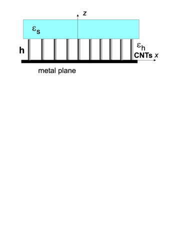
Finite-thickness slab of CNTs, embedded into a host matrix with the relative permittivity , is shown in Fig. 1. It forms two-dimensional periodic structure in the -plane with the square lattice (for simplicity) and the lattice constant . The radius of the CNT and the lattice constant are taken to be nm and nm, respectively. For the eigenwaves propagating in the arrays of infinitely long carbon nanotubes, space-time dependence of fields and currents is taken as . The approximation used in the following consideration is adopted from IgorPRB .
The surface conductivity for thin CNTs is highly anisotropic; namely, the axial component of the conductivity tensor is much larger than its azimuthal component due to quantum effects Slepyan . For this reason one can neglect by the azimuthal current on a CNT surface compared with the axial current. As a consequence, one can also neglect -component of the magnetic field and as a result, Maxwell’s equations are split into two subsystems describing the TM and TE waves. The following consideration will relate to TM-modes, whose electric field lies in the -plane because fields of TE-modes do not interact with thin CNTs. The effective medium model Minsk ; PNF will be employed. In the framework of the effective medium model, the CNT array can be considered as a uniaxial material with the relative permittivity dyadic
| (4) |
Transverse components of the diagonal permittivity tensor are equal to since carbon nanotubes do not affect the electric field vector, orthogonal to them due to very small thickness and very low azimuthal conductivity of CNTs. As shown in Minsk ,
| (5) |
where is the wavenumber in free space, is the effective plasma wavenumber, and is the effective inductance per unit length which includes the kinetic inductance and the electromagnetic inductance which can be neglected compared to the kinetic one, so BurkeNT ; is the permeability of vacuum and the parameter , where is the permittivity of vacuum, is responsible for losses. Thus the material behaves as a uniaxial free-electron plasma, where electrons can move only along -direction. Apparently, this corresponds to an indefinite medium at frequencies below the plasma frequency, because the permittivity in the directions orthogonal to the tubes equals to . Dispersion equation for waves propagating in a uniaxial crystal is Land
| (6) |
where . Substituting (5) into Eq. (6) one obtains:
| (7) |
It describes a typical conic-type dispersion. This cone is similar to the surface derived for the numerical model which accounts for periodicity of the CNT array (e.g., Fig. 3 from IgorPRB ). Applicability of the effective medium model was verified by comparing with the results of the electrodynamic model IgorPRB . An excellent agreement with more accurate theory occurs within a wide range of transversal wave numbers, at least for , in the mid-IR range for nm Giant .
II.3 Waveguide properties of finite-thickness slabs of carbon nanotubes
The following is to show that backward waves can propagate in the arrays of vertically standing CNTs. First, for simplicity consider CNTs placed between perfect electric conductor (PEC) and perfect magnetic conductor (PMC) planes, where the PMC boundary models the open-ended interface with free space. Assuming that waves propagate in the -direction, i.e. , the relation between the transversal wave vector component and the wavenumber in free space follows from Eq. (7):
| (8) |
where , is the integer determining a number of field variations along CNTs (the transverse resonant condition). Assuming , one can readily show that the derivative , if and . Thus, in this regime the finite-thickness slab supports propagation of backward waves, because the group velocity is in the opposite direction to phase velocity. This property can be understood also from considering a planar waveguide filled with a CNT array (the array axis is orthogonal to the walls of the waveguide). The propagation constant of the TM mode along the waveguide is equal to
| (9) |
where is a positive integer and is the height of the waveguide SpatD . If , backward-wave propagation is allowed when and forbidden for .
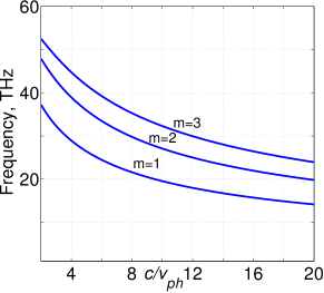
Figure 2 illustrates dispersion of this idealized structure. Here, all TM modes are backward waves; ; the plasma frequency is calculated to equal 58.7 THz.
Waveguide field components read as
| (10) |
where is the amplitude of the -th mode and
| (11) |
is the transverse wave impedance for the TM waves. Here is the wave impedance of vacuum. The spectrum of TE modes is the same as in a parallel-plane waveguide, filled with the dielectric with permittivity ; CNTs do not affect the TE modes propagation. All TE modes are forward ones and are not interesting for our purposes. Compared to optical MM made of resonant elements like split-ring resonators, dramatically increased bandwidth of backward-wave propagation is seen that gives the ground to consider CNT arrays as a perfect backward-wave metamaterial.
Then consider a more realistic structure, namely, CNTs with open ends, adjoining with a half-space, filled in with a dielectric, characterized with the relative permittivity , as shown in Fig. 1. In the framework of the effective medium theory the transfer matrix method Born can be used analyzing this structure. The transfer matrix components for the layer of carbon nanotubes have the form:
| (12) |
where is defined by formula (11). The transfer matrix (12) allows recalculation of tangential components of the electric and magnetic fields from the plane to . In contrast to the case of the plane plate waveguide bounded by PEC and PMC planes, is not fixed and depends on the waveguide propagation constant according to Eq. (7). The transfer matrix method allows easy calculations for any problems related to multilayered structures. For the simple case of surface waves propagating in the slab of CNTs with open ends, whose fields attenuate exponentially from the interface with surrounding medium, which is the dielectric with permittivity in our case, dispersion is given by the equation PNF :
| (13) |
which can be solved numerically.
II.4 Eigenmodes, phase matching and losses
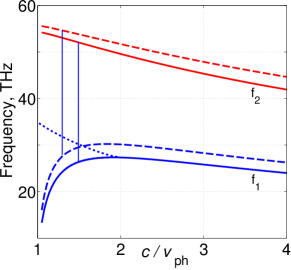
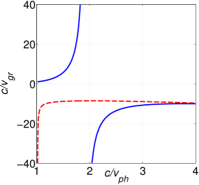
Complex propagation constant was calculated by numerically solving Eq. (13). Dispersion diagram for two lowest modes, calculated for two different thicknesses of the CNT layer, is shown in Fig. 3. Here, reduced wave vector is a slow-wave factor (the ratio of speed of light to the phase velocity), which represents effective refraction index .
Frequencies and dispersion of the allowed propagating EMW (eigenmodes) are determined by the thickness and effective parameters of the metaslab and, hence, can be adjusted. Appearance of the positive dispersion for small slow-wave factors and stop-light regime can be explained taking into account that directions of the Poynting vector in the metaslab and in the upper bounding dielectric (here, air) are opposite and the total energy flux stops if overall energy flows in both areas become equal. The branch of which descends down to the stop light point of the dispersion curve at approximately 27.5 THz for m is characterized by a complex constant corresponding to a huge damping. (Such a branch is not shown for m.) Imaginary part, , is not shown. Waves with complex propagation constants appear in a stop band if dispersion changes a sign and exist even in a lossless case (see radiofiz , also DWM , Fig. 6). These waves do not transfer energy because can be excited only as pairs of complex conjugate solutions and their fields can be represented in the form of standing waves with decaying amplitudes [see DWM , Eq. (28)].
Phase of NLO polarization oscillation at 2 at a given point in the metamaterial is determined by its wave vector 2, whereas that of the emitted SH – by the wave vector . Hence, to achieve phase matching, the phase velocities of both waves, and must be equal. Such a possibility for ordinary fundamental and BWSH waves is shown in Fig. 3. Here, the vertical lines show frequencies and that correspond to one and the same slow-wave factors . For m, = 52.37 THz and , whereas for m, = 55 THz and . For m, the wavelength of the the wave at in CNTs is about m, which corresponds to about m in free space. Figure 3 demonstrates that positions and dispersion of TM modes depend on the length of CNTs. It proves the possibility to ensure and to adjust to different frequencies the co-existence of ordinary fundamental and BWSH waves with equal phase velocities and contra-directed energy fluxes.
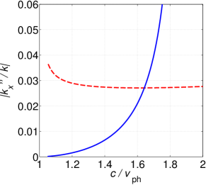
Optical losses of EMWs are represented by imaginary part of the propagation constant . For carbon nanotubes, magnitude of is determined by the relaxation time at frequencies below optical transitions. At low frequencies, including those close to a few terahertz, at room temperature is estimated as s Slepyan ; Hanson . Fig. 4 shows an attenuation of both modes in the proximities of frequencies of the phase matched fundamental and BWSH waves.
III Backward-wave second harmonic generation in pulsed regime
In this section, SHG will be investigated for the case of fundamental EMW falling in the positive dispersion frequency domain and its SH in the negative one (Fig. 3). To achieve phase matching, phase velocities of the fundamental and SH waves must be co-directed. This means that the pulse of SH will propagate against the pulse of the fundamental radiation. Such extraordinary NLO coupling scheme dictates exotic properties of the frequency-doubling ultracompact NLO mirror under consideration Mir ; APA2016 . Our goal is to investigate the characteristic magnitudes of the metamaterial nonlinearity and of the fundamental field intensity that would enable an appreciable output of BWSHG provided that the phase-matching is achieved. A simplified model of plane travelling waves will be used for such a purpose.
III.0.1 Basic Equations
Electric and magnetic components of the waves and corresponding nonlinear polarizations at and are defined as
| (14) | |||
| (15) | |||
| (16) | |||
| (17) |
Amplitude of the first harmonic (FH) and of the SH, , are given by the equations:
| (18) | |||
| (19) |
Here, and are group velocities and absorption indices at the corresponding frequencies, . Parameter for ordinary, and for backward wave. With account for , , , we introduce effective nonlinear susceptibility , amplitudes and , the coupling parameters and , the loss and phase mismatch parameters and , the metaslub thickness , the position and the time instant . It is assumed that , is the pump pulse length and is duration of the input fundamental pulse. Quantities are proportional to the time dependent photon fluxes. Then Eqs. (18) and (19) are written as
| (20) | |||
| (21) |
In the case of magnetic nonlinearity, , equations for amplitudes take the form:
| (22) | |||
| (23) |
Then, equations for amplitudes , where , take the form of (20) and (21), with coupling parameters given by and . In both cases, is characteristic medium length required for significant NLO energy conversion. Only the most favorable case of exact phase matching will be considered below.
The following values and estimates, which are relevant to the MM made of nanotubes of height m (Figs. 4 and 5), were used at numerical simulations. For pulse duration of ps, the spectrum bandwidth is on the order of THz. Hence, , and phase matching can be achieved for the whole frequency band. This becomes impossible at fs because . Phase matching is achieved at m-1, m-1 (Fig. 3). Then one finds m-1, m-1. Since losses for the second mode is greater, the characteristic metaslab thickness corresponding to extinction is estimated as , , m, which is about 10 wavelengths in the medium. The fundamental pulse length is m, which is 15 times greater than . The later indicates that whereas some transients occur at the pulse forefront and the tail, the quasistationary process establishes through almost the whole pulse duration. At ps, which is still acceptable, the effect of the transient processes significantly increases.
The input pulse shape was chosen close to a rectangular form
| (24) |
where , is duration of the pulse front and tail, and is shift of the front relative to . Magnitudes and were selected for numerical simulations. Coupling parameter is proportional to strength of the input pump field and presents a ratio of the input pulse length and characteristic nonlinear conversion length.
III.0.2 Transparent NIM slab
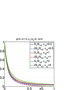
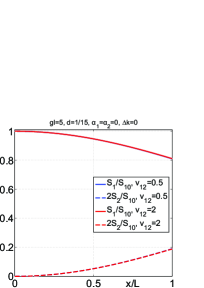
In order to show unparallel properties of the BWSHG in a frequency double domain positive/negative spatially dispersive slab, first, consider a loss-free slab that supports ordinary EMW at fundamental frequency and BEMW at SH frequency (, ).
(a) (b)
(c) (d)
(a) (b)
(c) (d)
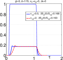
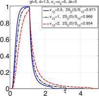
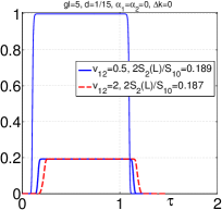
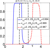
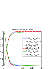
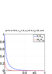
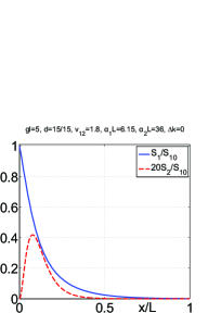
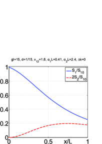
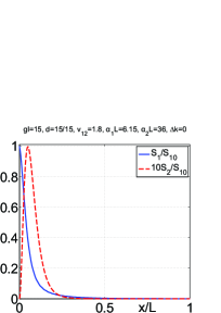
Unusual properties of SHG in NIMs in the pulsed regime stem from the fact that it occurs only inside the traveling pulse of fundamental radiation. Generation begins on the leading edge of the pulse, grows towards its trailing edge, and then exits the pulse with no further changes. Since the fundamental pulse propagates across the slab, duration of the contra-propagating SH pulse appears longer than the fundamental one. Basically, depletion of the fundamental radiation along the pulse and the conversion efficiency depend on its initial maximum intensity, phase matching and group velocities of pulses. Ultimately, properties of BWSHG are anticipated to depend on ratio of the fundamental pulse and the slab lengths. Such extraordinary behavior is illustrated in Fig. 6. Figure 6(a) displays rectangular shape of the input fundamental pulse entering the slab at (the blue rectangular plot). Shapes of the output pulses of BWSH traveling in the opposite, reflection direction and exiting the slab at are depicted by the lower blue and red plots for the input pulse length which is 15 times longer than the metaslab thickness (), and for two different group velocities. This case is close to continuous-wave regime. Figure 6(b) also show results of numerical simulations for shapes of output BWSH pulses for the same input pulse amplitude corresponding to , however, for the pulse length 1.5 times shorter than the metaslab thickness (). The plots demonstrate that output BWSH pulse becomes longer and its shape significantly differs from the shape of input fundamental pulse. Such a behavior is due to the fact that non-stationary transient processes at pulse edges that does not play significant role in the first case become important in the second case. Figures 6(c) and (d) depict the pulse energy (quantum) conversion efficiency and depletion of energy of the of the fundamental pulse along the slab and at the corresponding exits for the same coupling parameter .
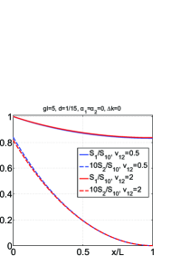
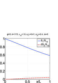
Fundamental differences between BWSHG and SHG in ordinary materials are seen from comparison of Fig. 6 and Fig. 7. In the first case, SH propagate against the fundamental pulse towards its greater magnitudes. The gap between the plots is inverse proportional to the conversion efficiency. It is seen from comparison of plots in Figs. 6 c and d that energy conversion efficiency grows with increase of the ratio (thicker MM slabs) and is almost independent on the dispersion of the group velocities for the given range of the select parameters. The plots satisfy to Manley-Rove (the energy conservation) law: the difference between the the number of pairs of photons in FH and the number of photons in SH () is a constant along the slab, which magnitude decreases with increase of the parameter Sl ; APB ; OL . Total number of annihilated pair of photons in the FH ( is equal to the number of output SH photons . In contrast, for ordinary materials and co-propagating waves, a sum of the the number of pairs of photons in FH and the number of photons in SH () is a constant along the slab. Shape, width and delay of the output pulses of SH generated in ordinary and BW materials is also differ.
(a) (b)
(c) (d)
III.0.3 Lossy NIM slab
Figure 8 presents the results of numerical simulations for energy conversion efficiency at BWSHG with account for the above calculated losses and group velocities pertinent to the given frequencies and the given MM.
(a) (b)
(c) (d)
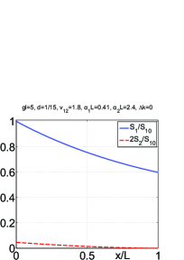
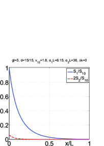
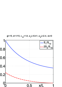
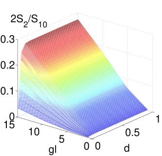
Figures 8 and 9 show that conversion efficiency grows with increase of the input pulse amplitude. However, the important unparalleled property is that nonlinear reflectivity rapidly saturates with increase of the metaslab thickness. Such unusual behavior is due to backwardness of SH which propagates against the fundamental beam and is predominantly generated in the area where FH is not yet significantly absorbed. It is seen that quantum nonlinear reflectivity of frequency doubling meta-mirror may reach the values of about ten percents at given values of the parameter . The power reflectivity is two times greater. Such a dependence is in stark contrast with SHG in ordinary materials as seen from comparison with Fig. 10. It shows corresponding dependencies in the case of ordinary material with all other parameters the same as in Figs. 8. It is seen that, in the latter case, SH reaches maximum inside the slab which is due to the interplay of nonlinear conversion and absorption processes. That means the pump strength and the slab thickness must be mutually optimized in this case to maximize the SH output.
IV Conclusions
We show the possibility to engineer the metamaterials that satisfy to a set of requirements of paramount importance for realization of unparallel nonlinear photonic processes which change photon frequency and propagation direction. The proposed metamaterials enable a set of travelling electromagnetic waves i) which frequencies satisfy to energy conservation low for nonlinear-optical frequency-conversion processes; ii) some of them are extraordinary backward waves with contra-directed energy flux and phase velocity, whereas other(s) are ordinary waves; iii) contra-propagating waves have equal phase velocities, i.e., are phase matched; iv) such properties can be adjusted to different frequencies. Frequency mixing of backward and ordinary waves possess fundamentally different properties compared to they ordinary counterparts and have important breakthrough applications in photonics. Current mainstream in crafting metamaterials that ensure backward waves relies on engineering the nanoscopic LC circuits that provide negative magnetic response at optical frequencies. The described in this paper approach is fundamentally different and bases on engineering the tailored coexisting negative and positive dispersion which dictates particular relationship between the frequencies and wavevectors of electromagnetic modes.
Such a general possibility is demonstrated through numerical simulations making use a particular example of the ”carbon nanoforest.” It is the metamaterial made of carbon nanotubes of particular diameter, height and spacing standing on metallic surface. We show that the negative and sign-changing dispersions pertinent to such metamaterial can be tailored to support phase matched backward-wave second harmonic generation in the THz and near IR frequency ranges. Losses introduced by the metallic properties of carbon nanotubes and by the particular nano-waveguide modes were investigated and appeared different for the coupled harmonics. Most practically important, pulsed, regimes of second harmonic generation in such metamaterials was described with the simplified model of plane travelling waves. A set of coupled partial differential equations was employed which accounted for dispersion of group velocities and losses. Since the generated second harmonic travels in the direction opposite to the fundamental wave, the investigated process presents a model of the miniature frequency doubling metareflector/metasensor with unparalleled properties.
The described approach can be applied to engineering the metamaterials that employ tailored positive and negative dispersion to enable extraordinary phase-matched three-wave mixing of contra-propagating waves and their optical parametric amplification which will be described elsewhere.
Acknowledgements
This material is based upon work supported in part by the U. S. Army Research Laboratory and the U. S. Army Research Office under grant number W911NF-14-1-0619 and by the Russian Foundation for Basic Research under grant RFBR 15-02-03959A.
References
- (1) L. D. Landau and E. L. Lifshits, [Electrodinamics of Continuous Media], Ch. 9, 2nd. ed., Pergamon Press, New York (1960).
- (2) V. G. Veselago, “Properties of materials having simultaneously negative values of dielectric and magnetic susceptibilities,” Sov. Phys. Solid State 8, 2854–2856 (1967).
- (3) V.G. Veselago, “The electrodynamics of substances with simultaneously negative values of and ,” [Sov. Phys. Usp. 10, 509–514 (1968)].
- (4) D.R. Smith, W. Padilla, D.C. Vier, S.C. Nemat-Nasser, and S. Shults, “Composite medium with simultaneously negative permeability and permittivity,” Phys. Rev. Lett. 92, 4184–4187 (2000).
- (5) R. A. Shelby, D. R. Smith, and S. Schultz, “Experimental verification of a negative index of refraction,” Science 292, 77–79 (2001).
- (6) D.R. Smith, J. B. Pendry, and M. C. K. Wiltshire, “Metamaterials and negative refractive index,” Science 305, 788–790 (2004).
- (7) S. Linden, C. Enkrich, M. Wegener, J. Zhou, T. Koschny, and C. M. Soukoulis, “Magnetic response of metamaterials at 100 Terahertz,” Science 306, 1351–1353 (2004).
- (8) Z. Zhang, W. Fan, B. K. Minhas, A. Frauenglass, K. J. Malloy, and S. R. J. Brueck, “Midinfrared resonant magnetic nanostructures exhibiting a negative permeability,” Phys. Rev. Lett. 94, 037402 (2005).
- (9) A. N. Grigorenko, A. K. Geim, N. F. Gleeson, Y. Zhang, A. A. Firsov, I. Y. Khrushchev, and J. Petrovic, “Nanofabricated media with negative permeability at visible frequencies,” Nature, 438, 335–337 (2005).
- (10) V. M. Shalaev, W. Cai, U. Chettiar, H.-K. Yuan, A. K. Sarychev, V. P. Drachev, and A. V. Kildishev, “Negative index of refraction in optical metamaterials,” Optics Letters 30, 3356–3358 (2005).
- (11) S. Zhang, W. Fan, N. C. Panoiu, K. J. Malloy, R. M. Osgood, and S. R. J. Brueck, “Experimental demonstration of near-infrared negative-index metamaterials,” Phys. Rev. Lett. 95, 137404 (2005).
- (12) V. M. Shalaev, “Optical negative-index metamaterials,” Nat. Photonics 1, 41–48 (2007).
- (13) M. Freebody, “Metamaterials: photonic sleight of hand,” Photonics Spectra, 44–47, September (2011).
- (14) W. Cai and V. Shalaev, Optical metamaterials, fundamentals and applications, Springer-Verlag New York, 2010.
- (15) I.V. Shadrivov, A.A. Zharov, and Yu.S. Kivshar, “Second-harmonic generation in nonlinear left-handed metamaterials,” JOSA B 23, 529- 534 (2006).
- (16) A.K. Popov, V.V. Slabko, and V.M. Shalaev, “Second harmonic generation in left-handed metamaterials,” Laser Phys. Lett. 3, 293–296 (2006).
- (17) A.K. Popov and V.M. Shalaev, “Negative-index metamaterials: second harmonic generation, Manley - Rowe relations and parametric amplification,” Appl. Phys. B Lasers Opt. 84, 131 -137 (2006).
- (18) A.K. Popov and V.M. Shalaev, “Compensating losses in negative-index metamaterials by optical parametric amplification,” Opt. Lett. 31, 2169 -2171 (2006).
- (19) A. K. Popov, “Nonlinear optics of backward waves and extraordinary features of plasmonic nonlinear-optical microdevices,” Eur. Phys. J. D 58, 263–274 (2010) (topical issue on Laser Dynamics and Nonlinear Photonics).
- (20) A. K. Popov and V. M. Shalaev, “Merging nonlinear optics and negative-index metamaterials,” in Metamaterials: Fundamentals and Applications IV, Alan D. Boardman, Nader Engheta, Mikhail A. Noginov, Nikolay I. Zheludev, Editors: Proc. SPIE, 8093, 809306-27 (2011).
- (21) A. Rose, Da Huang, and D.R. Smith, “Controlling the second harmonic in a phase-matched negative-index metamaterial,” Phys. Rev. Lett. 107, 063902–4 (2011).
- (22) H. Suchowski, K. O Brien, Z.J. Wong, A. Salandrino, X. Yin, and X. Zhang, “Phase mismatch free nonlinear propagation in optical zero-index materials,” Science 342, 1223–1226 (2013).
- (23) A.K. Popov and S.A. Myslivets, “Second harmonic generation and pulse shaping in positively and negatively spatially dispersive nanowaveguides: comparative analysis.” http://arxiv.org/abs/1507.07167, Journal Opt. Quant. Electron. 48(2), 1–10 (2016), DOI: 10.1007/s11082-016-0416-2.
- (24) A.K. Popov, M.I. Shalaev, S.A. Myslivets, V.V. Slabko, and I.S. Nefedov, “Enhancing coherent nonlinear-optical processes in nonmagnetic backward-wave materials,” Appl. Phys. A 109, 835–840 (2012), doi:10.1007/s00339-012-7390-8.
- (25) A.K. Popov, M.I. Shalaev, V.V. Slabko, S.A. Myslivets, and I.S. Nefedov, “Nonlinear backward-wave photonic metamaterials,” Advances in Science and Technology 77, 246–252 (2013), doi:10.4028/www.scientific.net/AST.77.246.
- (26) A.K. Popov, V.V. Slabko, M.I. Shalaev, I.S. Nefedov, and S.A. Myslivets, “Nonlinear optics with backward waves: Extraordinary features, materials and applications,” Solid State Phenomena 213, 222–225 (2014), doi:10.4028/www.scientific.net/SSP.213.222.
- (27) V. M. Agranovich, Y. R. Shen, R. H. Baughman, and A. A. Zakhidov, “Linear and Nonlinear Wave Propagation in Negative Refraction Metamaterials,” Phys. Rev. B 69, 165112 (2004).
- (28) V. M. Agranovich and Yu. N. Gartstein, “Spatial dispersion and negative refraction of light,” Physics-Uspekhi (UFN) 176, 1051–1068 (2006) (Also in Physics of Negative Refraction (Eds C.M. Krowne, Y. Zhang) (Springer, 2007).
- (29) I.V. Lindell, S.A. Tretyakov, K.I. Nikoskinen, and S. Ilvonen, “BW media - - media with negative parameters, capable of supporting backward waves,” Microwave Opt. Techn. Let. 31, 129–133 (2001), doi:10.1002/mop.1378.
- (30) D. R. Smith and D. Schurig, “Electromagnetic wave propagation in media with indefinite permittivity and permeability tensors,” Phys. Rev. Lett. 90, 077405 (2003).
- (31) J. B. Pendry, “Negative refraction makes a perfect lens,” Phys. Rev. Lett. 85, 3966 (2000).
- (32) X. Zhang and Z. Liu, “Superlenses to overcome the diffraction limit,” Nature Materials 7, 435 (2008).
- (33) G. Shvets, S. Trendafilov, J.B. Pendry, and A. Sarychev, “Guiding, focusing, and sensing on the subwavelength scale using metallic wire arrays,” Phys. Rev. Lett. 99, 053903 (2007).
- (34) Y. Liu, G. Bartal, and X. Zhang, “All-angle negative refraction and imaging in a bulk medium made of metallic nanowires in the visible region,” Optics Express 16, 15439–49 (2008).
- (35) A. Ono, J. Kato, and S. Kawata, “Subwavelength optical imaging through a metallic nanorod array,” Phys. Rev. Lett. 95, 267407 (2005).
- (36) P. A. Belov, A. A. Orlov, A. V. Chebykin, and Yu. S. Kivshar, “Spatial dispersion in layered metamaterials,” Proc. Internat. Conf. on Electrodynamics of Complex Materials for Advanced Technologies, PLASMETA’11, September 21-26, Samarkand, Uzbekistan, pp.30–31.
- (37) E.E. Narimanov, “Photonic hypercrystal,” Phys. Rev. X 4, 041014 (2014).
- (38) C. Argyropoulos, N. M. Estakhri, F. Monticone, and A. Alù, “Negative refraction, gain and nonlinear effects in hyperbolic metamaterials,” Optics Express 21, 15037–15047 (2013).
- (39) M. Lapine, I. V. Shadrivov, and Yu. S. Kivshar, “Colloquium: Nonlinear metamaterials,” Review of Modern Physics 86, 1093–1123 (2014).
- (40) C. Duncan, L. Perrel, S. Palomba, M. Lapine, B. T. Kuhlmey, and C. M. de Sterke, “New avenues for phase matching in nonlinear hyperbolic metamaterials,” Scientific Reports 5, 08983 (2015).
- (41) S. Mokhov, R. El-Ganainy, and D.N. Christodoulides, “Power circulation via negative energy-flux wormholes in optical nanowaveguides,” Opt. Express 14, 3255- 3262 (2006).
- (42) A. Salandrino, D.N. Christodoulides, “Negative index Clarricoats-Waldron waveguides for terahertz and far infrared applications,” Opt. Express 18, 3626–3631 (2010).
- (43) I. S. Nefedov, “Electromagnetic waves propagating in a periodic array of parallel metallic carbon nanotubes,” Phys. Rev. B 82, 155423 (2010).
- (44) I. Nefedov and S. Tretyakov, “Ultabroadband electromagnetically indefinite medium formed by aligned carbon nanotubes,” Phys. Rev. B, 84, 113410 (2011).
- (45) S. Fan, M. G. Chapline, N. R. Franklin, T. W. Tombler, A. M. Cassell, and H. Dai, “Self-oriented regular arrays of carbon nanotubes and their field emission properties,” Science 283, 512 (1999).
- (46) Y. Lin, F. Lu, Y. Tu, and Z. Ren, “Glucose biosensors based on carbon nanotube nanoelectrode ensembles,” Nano Letters 4, 191 (2004).
- (47) Y. Wang et al., “Receiving and transmitting light-like radio waves: Antenna effect in arrays of aligned carbon nanotubes,” Appl. Phys. Lett. 85, 2607 (2004).
- (48) M. S. Dresselhaus, “Applied physics: nanotube antennas,” Nature Materials 432, 959 (2004).
- (49) G. Y. Slepyan, S. A. Maksimenko, A. Lakhtakia, O. Yevtushenko, and A. V. Gusakov, “Electrodynamics of carbon nanotubes: Dynamic conductivity, impedance boundary conditions, and surface wave propagation,” Phys. Rev. B 60, 17136 (1999).
- (50) G. V. Hanson, “Fundamental transmitting properties of carbon nanotube antennas,” IEEE Trans. on Ant. and Prop. 53, 3426–3434 (2005).
- (51) J. Hao and G. V. Hanson, “Electromagnetic scattering from finite-length metallic carbon nanotubes in the lower IR bands,” Phys. Rev. B 74, 035119 (2006).
- (52) P.J. Burke, S. Li, and Z. Yu, “”Quantitative theory of nanowire and nanotube antenna performance,” IEEE Trans. on Nanotechnology 5, 314-334 (2006).
- (53) A. Maffucci, G. Miano, and F. Villone, “A transmission line model for metallic carbon nanotube interconnects,” Int. J. Circ. Theor. Appl. 36, 31–51 (2008).
- (54) G. Miano and F. Villone, “An integral formulation for the electrodynamics of metallic carbon nanotubes based on a fluid model,” IEEE Trans. on on Antennas and Propagation 54, 2713 (2006).
- (55) S. M. Mikki and A. A. Kishk, “Mean-field electrodynamic theory of aligned carbon nanotube composites,” IEEE Trans. Antenna and Propag., 57, 1412–1419 (2009).
- (56) I. S. Nefedov and S. A. Tretyakov, “Effective medium model for two-dimensional periodic arrays of carbon nanotubes,” Photonics and Nanostructures - Fundamentals and Applications, 9, October 2011, 374-380 (2011) (TaCoNa-Photonics 2010).
- (57) I. S. Nefedov and C. R. Simovski, “Giant radiation heat transfer through micron gaps,” Phis. Rev. B 84, 195459 (2011).
- (58) P. A. Belov, R. Marques, S. I. Maslovski, I. S. Nefedov, M. Silveirinha, C. R. Simovski, and S. A. Tretyakov, “Strong spatial dispersion in wire media in the very large wavelength limit,” Phys. Rev. B 67, 113103 (2003).
- (59) M. Born and E. Wolf, Principles of Optics (Second edition. Pergamon Press, Oxford-London-New York, 1964).
- (60) V. N. Ivanov, N. P. Demchenko, I. S. Nefedov, R. A. Silin, and A. G. Schuchinsky, “Waves in a tangentially magnetiozed ferrite layer (numerical electrodynamic analysis and regular asymptotical expansions),” Izvestiya Vysshikh Uchebnykh Zavedenii Radiofizika, 32, 764-776 (1989).
- (61) I. S. Nefedov, A. J. Viitanen, and S. A. Tretyakov, “Propagating and evanescent modes in two-dimensional wire media,” Phys. Rev. B 71, 046612 (2005).
- (62) G. D.’Aguanno, M. Centini, M. Scalora, C. Sibilia, Y. Dumeige, P. Vidacovic, J. A. Levenson, M. J. Bloemer, C. M. Bowden, J. W. Haus, and M. Bertolotti, “Photonic band edge effects in finite structures and applications to interactions,” Phys. Rev. E, 64, 016609 (2001).
- (63) G. Ya. Slepyan, S. A. Maksimenko, V. P. Kalosha, J. Herrmann, E. E. B. Campbell, and I. V. Hertel, “Highly efficient high-order harmonic generation by metallic carbon nanotubes,” Phys. Rev. A 60, R777- R780 (1999).
- (64) G. Y. Guo, K. C. Chu, D. Wang, and C. Duan, “Linear and nonlinear properties of carbon nanotubes from first-principles calculations,” Phys. Rev. B 69, 205416 (2004).
- (65) G. Ya. Slepyan, A. A. Khrutchinskii, A. M. Nemilentsau, and S. A. Maksimenko, “High-order optical harmonic generation on carbon nanotubes: quantum-mechanical approach,” Int. J. of Nanoscience 3, 343–354 (2004).
- (66) D. T. Morris, C. L. Pint, R. S. Arvidson, A. Lüttge, R. H. Hauge, A. A. Belyanin, G. L. Woods, and J. Kono, “Midinfrared third-harmonic generation from macroscopically aligned ultralong single-wall carbon nanotubes,” Phys. Rev. B 87, 161405(R) (2013).
- (67) A. M. Nemilentsau, G. Ya. Slepyan, A. A. Khrutchinskii, and S. A. Maksimenko, “Third-order optical nonlinearity in single-wall carbon nanotubes,” Carbon 44, 2246–2253 (2006).
- (68) A. K. Popov and S. A. Myslivets, “Nonlinear-optical metamirror,” Appl. Phys. A 103, 725–729 (2011).
- (69) A. K. Popov aand S. A. Myslivets, “Nonlinear-optical frequency-doubling meta-reflector: pulsed regime,” http://arxiv.org/abs/ 1508.03135, Applied Physics A, 122(1), 1–6, (2016) DOI 10.1007/s00339-015-9534-0.