Cascade dynamics of thermomagnetic avalanches in superconducting films with holes
Abstract
The sub-microsecond dynamics of thermomagnetic avalanches in superconducting films with non-conducting holes (antidots) is considered. When such an avalanche reaches a hole, it is quickly filled with magnetic flux, and often its rim becomes unstable and a second avalanche is nucleated. In this work the time- and space-resolved behavior of such cascading avalanche behavior is determined using numerical simulations. Results are presented for films with holes of different shape. It is found that holes with sharp corners are those that most frequently create secondary avalanches, and they tend to nucleate in corners. Magneto-optical imaging of Nb films patterned with the same set of holes strongly supports the numerical results.
In the critical-state of type-II superconductors,Bean (1964) the metastable system is susceptible to abrupt redistributions of magnetic flux and electrical currents. For thin samples experiencing a perpendicular magnetic field, even tiny field changes may cause large amounts of flux to jump. Typically, such an avalanche lasts less than a microsecond,Wertheimer and J. le G. Gilchrist (1967); Leiderer et al. (1993) and propagates in a fingering structure, often strongly branched, as observed in films of many materialsDeSorbo and Newhouse (1962); Dolan (1973); Durán et al. (1995); Johansen et al. (2002); Rudnev et al. (2003); Altshuler et al. (2004); Wimbush et al. (2004); Rudnev et al. (2005); Motta et al. (2013); Baziljevich et al. (2014) using magneto-optical imaging (MOI). These dramatic events are caused by an instability Mints and Rakhmanov (1981) creating a runaway of flux motion accompanied by local heating. Linear stability analysis of the thermomagnetic model has explained why there exist onset threshold values both in applied magnetic field and temperature.Mints and Brandt (1996); Denisov et al. (2006); Albrecht et al. (2007) Numerical simulationsAranson et al. (2001, 2005); Vestgården et al. (2011); J. I. Vestgården et al. (2012) have confirmed that the equations representing the thermomagnetic scenario of thin superconductors in perpendicular field indeed give rise to the type of dendritic patterns found experimentally.
Interestingly, MOI observations have also revealed that the avalanches show systematic new behavior when meeting macroscopic nonuniformities in the sample. E.g., when a layer of normal metal covers part of the superconducting film, an avalanche tends to change propagation direction at the boundary between bare and coated film.Albrecht et al. (2005); Mikheenko et al. (2013) A recent study of NbN films coated with a Cu layer showed that the deflection of the avalanche branches tend to follow Snell’s law with a refraction index of 1.4, a number also found to be the ratio of avalanche propagation velocities in the bare and coated film.Mikheenko et al. (2015) Other experiments have shown that inhomogeneities in the form of patterned holes in the superconducting film also modify the avalanche behavior. E.g., in films with regular arrays of small holes (antidots), one finds strong guidance of the avalanche branches.Vlasko-Vlasov et al. (2000); Menghini et al. (2005); Motta et al. (2011, 2014) How avalanches are affected by large holes has also been investigated. In the work Ref. Olsen et al., 2007 the process of flux jumping into the central hole of a circular planar ring of MgB2 was studied, revealing major redistribution of the shielding currents. Recently,Colauto et al. (2013) macro-holes in Nb films were considered as potential traps, or stop holes, serving to limit the spatial extension of thermomagnetic avalanches.
The present work aims to reveal the utra-fast cascade dynamics of avalanches propagating in superconducting films patterned with macro-holes. Space- and time-resolved results from quantitative numerical simulations for samples with holes of various shapes are presented, and compared with avalanche behavior observed in a similarly patterned superconducting film.
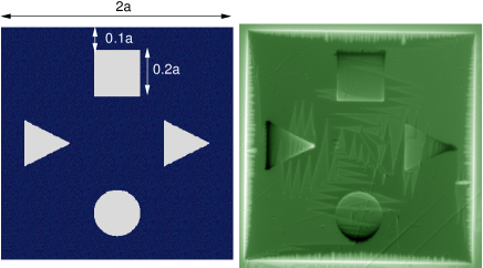
MOI experiments were conducted on a square Nb film of sides mm and thickness nm. Using optical lithography the film was patterend with holes shaped as a square, a circle, and two triangles, see Fig. 1 (left). Each hole has a dimension , and is placed adistance from the nearest edge. To visualize the flux density a ferrite-garnet film with large Faraday coefficientHelseth et al. (2002) was placed directly on the sample, and after cooling down in an optical cryostat, polarized light microscopy was performed.
The Nb film was first zero-field-cooled to K, a temperature sufficiently low for avalanches to occur. When a transverse magnetic field is gradually applied, flux begins to penetrate, and when reaching 2.5 mT one observes the magneto-optical image shown in Fig. 1 (right). The image was recorded with slightly uncrossed polarizers in the MOI setup, allowing to discriminate between flux into or out of the image plane. The central part of the film, which is in the Meissner state serves as reference color representing . The bright rim around the sample perimeter shows the applied field piling up outside the diamagnetic film. The image also shows a shallow flux penetration from the edge, in a pattern typical for critical-state behavior. Note that the holes are clearly visible in the image. All four holes display a dark side towards the sample edge, and a bright side towards the center. This bipolar (flux-antiflux) feature is caused by the additional field created by the shielding currents as they are forced to circumvent the holes.Baziljevich et al. (1996)
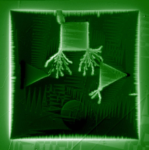
When the applied field reaches 2.8 mT the first avalanche event occurs, resulting in the final flux distribution shown in Fig. 2 (left). The avalanche started from the upper edge, and from there invaded the square hole through the thick finger seen to bridge the two regions. Then, from the two inner corners of the square hole secondary events started, resulting in two highly branched avalanches. Both of them reached their nearest triangular hole, which by their bright constrast, are seen to have received considerable amounts of flux. Then, as a final step in this cascade of events, the triangular hole on the right side releases its magnetic pressure in an avalanche consisting of 3 branches.
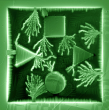
By increasing the field further, even more avalanches appear, and Fig. 2 (right) shows the flux distribution at the field of 4.35 mT. Here, all the holes have received flux, and one sees that some avalanches, e.g., both events starting from the right sample edge do not feed flux into any hole. Continued field ramping adds more and more avalanches, and the complexity in the overall pattern grows.
In the following we present results from numerical simulations of such sequences of events, thus allowing deeper insight into this ultrafast cascading behaviour.
The electrodynamical part of the problem is solved by time-integration of the Maxwell equations
| (1) |
with and , using implicit boundary conditions for edges and holes, as described in Ref. Vestgården et al., 2013. The material characteristics of the sample is the conventional power-law relation
| (2) |
where is the local temperature, is the critical current, and is the creep exponent. The temperature dependencies are and . The local heat is found by time-integration of
| (3) |
where is the specific heat, is the heat conductivity, is the coefficient of heat transfer to the substrate, and is the substrate temperature..
The simulations use the following parameters: K, = 5 m, A/m2, W/Km, J/Km3, and W/Km2. We set and restrict to . The sample dimensions are mm and nm, and the applied magnetic field is ramped at the constant rate of , from initially and .
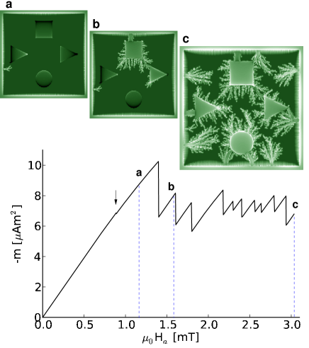
As the applied field gradually increases, shielding currents are induced in the sample, giving it a magnetic moment, . Figure 3 displays the moment as function of field, and shows that at low fields the magnitude of increases monotonously, as expected from the growing induced currents. Soon, the sheet current near the edge reaches the critical value , and magnetic flux starts to enter the sample along the rim. At the field of 0.8 mT a minor avalanche strikes near one of the triangular holes. The event is clearly visible in the flux distribution of image (a), but is hardly noticeable in the magnetic moment curve.
The next event occurs at mT, and is a much bigger avalanche, as here makes a large drop. Image (b) shows that this avalanche alters the flux distribution significantly, and hasfilled both the square and triangular hole on the right side with sizable amounts of flux. Thereafter, the magnetization curve shows that avalanche events continue to appear with irregular intervals and magnitudes. The simulation was ended at the applied field of mT, with the flux distributed as seen in image (c). During this field ramp a total of 11 avalanches took place, and the sequence of images of reproduces most features of the shown experimental images.
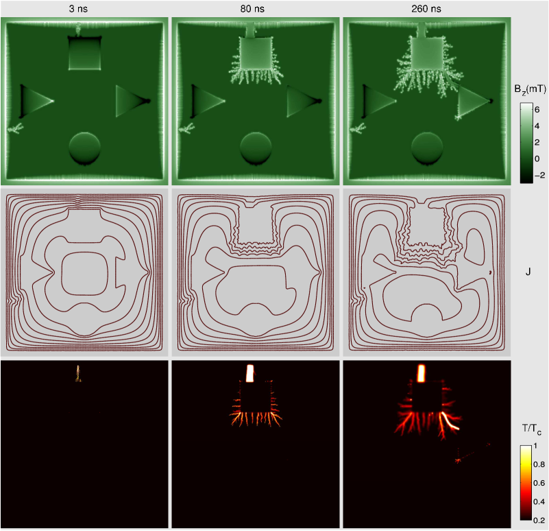
To illustrate the time evolution of an avalanche, the Fig. 4 shows snapshots from the simulations, recorded at three moments in time after nucleation of the event at mT. The figure presents maps of the flux density , the stream lines of the sheet current , and the local temperature . From the left column, one sees that already after 3 ns, a narrow channel of moving flux, accompanied by elevated temperature, is connecting the square hole to the flux reservoir outside the edge.
After 80 ns (middle column) this channel has grown in width, and the flux traffic has increased significantly. The -map shows that in the entire channel the temperature now rises well above . Via this opening the square hole becomes filled with flux, which in turn nucleates secondary avalanches from the edge of the hole. The corresponding -map confirms that a massive rearrangement of currents is taking place. Actually, at this stage the hole is more part of the outside than the inside of the superconductor, as far as shielding is concerned.
After 260 ns (right column) the secondary avalanches have penetrated deeper. In fact, one branch has reached another hole, namely the triangular one on the right side. That hole is now in being filled with flux via the narrow channel appearing as very bright in the -map.
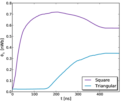
A more quantitative illustration of the interaction between avalanches and holes is presented in Fig. 5. The two graphs display the total flux entering the square and triangular hole as functions of time during the avalanche occurring at mT. First, flux is rapidly injected into the square hole with almost constant rate, while the flux inside the triangular hole stays constant. At around ns the flux in the square hole reaches a maximum. This occurs nearly at the same time as the flux in the triangular hole begins to increase. After 400 ns both curves reach a plateau as the avalanche comes to rest.
In the initial stage of the avalanche, the rate of change of the flux in the square hole is Wb/s. This represents the flux entering the hole while the channel to the external rim is heated above . From Fig. 4 one can estimate that the channel width is m, which means that in the channel the electric field amounts to V/m. For comparison, an estimate of the electric field at the sample’s outer edge created by the regular flux penetration gives mV/m. Note that in the present model no heat flows in the substrate below the holes. This suggests that the electrodynamics alone can lead to avalanche cascades between holes in a superconducting film.
In summary, the present work has shown that thermomagnetic avalanches in superconducting films tend to be attracted by holes in the film. The numerical simulations reveal the detailed dynamics at the various stages of an avalanche as it propagates from one hole to another. Typically, a hole becomes filled with flux via a narrow normal-state channel created between the film’s external edge and the hole. It is found that this often lead to secondary avalanches, which spread to neighboring holes or parts of the film not yet penetrated by flux. Holes with sharp corners, like square and triangular holes, are those that most frequently create avalanche cascades.
The samples were grown in Laboratório de Conformação Nanométrica (LCN-IF-UFRGS), and the lithography was made in Laboratório de Microfabricação (LMF/LNNano/CNPEM). The work was financially supported by the Brazilian funding agencies FAPESP and CNPq, and the program Science without Borders, as well as the CAPES-SIU-2013/10046 project ”Complex fluids in confined environments”.
References
- Bean (1964) C. P. Bean, Rev. Mod. Phys. 36, 31 (1964).
- Wertheimer and J. le G. Gilchrist (1967) M. R. Wertheimer and J. le G. Gilchrist, J. Phys. Chem. Solids 28, 2509 (1967).
- Leiderer et al. (1993) P. Leiderer, J. Boneberg, P. Brüll, V. Bujok, and S. Herminghaus, Phys. Rev. Lett. 71, 2646 (1993).
- DeSorbo and Newhouse (1962) W. DeSorbo and V. L. Newhouse, J. Appl. Phys. 33, 1004 (1962).
- Dolan (1973) G. J. Dolan, J. Low temp. Phys. 15, 111 (1973).
- Durán et al. (1995) C. A. Durán, P. L. Gammel, R. E. Miller, and D. J. Bishop, Phys. Rev. B 52, 75 (1995).
- Johansen et al. (2002) T. H. Johansen, M. Baziljevich, D. V. Shantsev, P. E. Goa, Y. M. Galperin, W. N. Kang, H. J. Kim, E. M. Choi, M.-S. Kim, and I. Lee, EPL 59, 599 (2002).
- Rudnev et al. (2003) I. A. Rudnev, S. V. Antonenko, D. V. Shantsev, T. H. Johansen, and A. E. Primenko, Cryogenics 43, 663 (2003).
- Altshuler et al. (2004) E. Altshuler, T. H. Johansen, Y. Paltiel, P. Jin, K. E. Bassler, O. Ramos, Q. Y. Chen, G. F. Reiter, E. Zeldov, and C. W. Chu, Phys. Rev. B 70, 140505 (2004).
- Wimbush et al. (2004) S. C. Wimbush, B. Holzapfel, and Ch. Jooss, J. App. Phys. 96, 3589 (2004).
- Rudnev et al. (2005) I. A. Rudnev, D. V. Shantsev, T. H. Johansen, and A. E. Primenko, Appl. Phys. Lett. 87, 042502 (2005).
- Motta et al. (2013) M. Motta, F. Colauto, W. A. Ortiz, J. Fritzsche, J. Cuppens, W. Gillijns, V. Moshchalkov, T. H. Johansen, A. Sanchez, and A. V. Silhanek, Appl. Phys. Lett. 102, 212601 (2013).
- Baziljevich et al. (2014) M. Baziljevich, E. Baruch-El, T. H. Johansen, and Y. Yeshurun, Appl. Phys. Lett. 105, 012602 (2014).
- Mints and Rakhmanov (1981) R. G. Mints and A. L. Rakhmanov, Rev. Mod. Phys. 53, 551 (1981).
- Mints and Brandt (1996) R. G. Mints and E. H. Brandt, Phys. Rev. B 54, 12421 (1996).
- Denisov et al. (2006) D. V. Denisov, D. V. Shantsev, Y. M. Galperin, E.-M. Choi, H.-S. Lee, S.-I. Lee, A. V. Bobyl, P. E. Goa, A. A. F. Olsen, and T. H. Johansen, Phys. Rev. Lett. 97, 077002 (2006).
- Albrecht et al. (2007) J. Albrecht, A. T. Matveev, J. Strempfer, H.-U. Habermeier, D. V. Shantsev, Y. M. Galperin, and T. H. Johansen, Phys. Rev. Lett. 98, 117001 (2007).
- Aranson et al. (2001) I. Aranson, A. Gurevich, and V. Vinokur, Phys. Rev. Lett. 87, 067003 (2001).
- Aranson et al. (2005) I. S. Aranson, A. Gurevich, M. S. Welling, R. J. Wijngaarden, V. K. Vlasko-Vlasov, V. M. Vinokur, and U. Welp, Phys. Rev. Lett. 94, 037002 (2005).
- Vestgården et al. (2011) J. I. Vestgården, D. V. Shantsev, Y. M. Galperin, and T. H. Johansen, Phys. Rev. B 84, 054537 (2011).
- J. I. Vestgården et al. (2012) J. I. Vestgården, D. V. Shantsev, Y. M. Galperin, and T. H. Johansen, Sci. Rep. 2, 886 (2012).
- Albrecht et al. (2005) J. Albrecht, A. T. Matveev, M. Djupmyr, G. Schütz, B. Stuhlhofer, and H. Habermeier, Appl. Phys. Lett. 87, 182501 (2005).
- Mikheenko et al. (2013) P. Mikheenko, A. J. Qviller, J. I. Vestgården, S. Chaudhuri, I. J. Maasilta, Y. M. Galperin, and T. H. Johansen, Appl. Phys. Lett. 102, 022601 (2013).
- Mikheenko et al. (2015) P. Mikheenko, T. H. Johansen, S. Chaudhuri, I. J. Maasilta, and Y. M. Galperin, Phys. Rev. B Rapid Comm. (2015).
- Vlasko-Vlasov et al. (2000) V. Vlasko-Vlasov, U. Welp, V. Metlushko, and G. W. Crabtree, Physica C 341, 1281 (2000).
- Menghini et al. (2005) M. Menghini, R. J. Wijngaarden, A. V. Silhanek, S. Raedts, and V. V. Moshchalkov, Phys. Rev. B 71, 104506 (2005).
- Motta et al. (2011) M. Motta, F. Colauto, R. Zadorosny, T. H. Johansen, R. B. Dinner, M. G. Blamire, G. W. Ataklti, V. V. Moshchalkov, A. V. Silhanek, and W. A. Ortiz, Phys. Rev. B 84, 214529 (2011).
- Motta et al. (2014) M. Motta, F. Colauto, J. I. Vestgården, J. Fritzsche, M. Timmermans, J. Cuppens, C. Attanasio, C. Cirillo, V. V. Moshchalkov, J. Van de Vondel, T. H. Johansen, W. A. Ortiz, and A. V. Silhanek, Phys. Rev. B 89, 134508 (2014).
- Olsen et al. (2007) Å. A. F. Olsen, T. H. Johansen, D. Shantsev, E.-M. Choi, H.-S. Lee, H. J. Kim, and S.-I. Lee, Phys. Rev. B 76, 024510 (2007).
- Colauto et al. (2013) F. Colauto, J. I. Vestgården, A. M. H. de Andrade, A. A. M. Oliveira, W. A. Ortiz, and T. H. Johansen, Appl. Phys. Lett. 103, 032604 (2013).
- Helseth et al. (2002) L. E. Helseth, A. G. Solovyev, R. W. Hansen, E. I. Il’yashenko, M. Baziljevich, and T. H. Johansen, Phys. Rev. B 66, 064405 (2002).
- Baziljevich et al. (1996) M. Baziljevich, T. H. Johansen, H. Bratsberg, Y. Shen, and P. Vase, Appl. Phys. Lett 69, 3590 (1996).
- Vestgården et al. (2013) J. I. Vestgården, P. Mikheenko, Y. M. Galperin, and T. H. Johansen, New J. Phys. 15, 093001 (2013).