K. Haze et al.Experimental demonstration of binary shaped pupil mask coronagraphs for telescopes with obscured pupils
instrumentation: high angular resolution—planetary systems—telescopes
Experimental demonstration of binary shaped pupil mask coronagraphs for telescopes with obscured pupils
Abstract
We present the fabrication and experimental demonstration of three free-standing binary shaped pupil mask coronagraphs, which are applicable for telescopes with partially obscured pupils. Three masks, designed to be complementary (labeled Mask-A, Mask-B, and Mask-C), were formed in 5 thick nickel. The design of Mask-A is based on a one-dimensional barcode mask. The design principle of Mask-B is similar, but has a smaller inner working angle and a lower contrast than Mask-A. Mask-C is based on a concentric ring mask and provides the widest dark region and a symmetric point spread function. Mask-A and Mask-C were both designed to produce a flexibly tailored dark region (i.e., non-uniform contrast). The contrast was evaluated using a light source comprising a broadband super-luminescent light-emitting diode with a center wavelength of 650 nm, and the measurements were carried out in a large vacuum chamber. Active wavefront control was not applied in this work. The coronagraphic images obtained by experiment were mostly consistent with the designs. The contrast of Mask-A within the ranges 3.3 - 8 and 8 - 12 was - and , respectively, where is the wavelength and is the pupil diameter. The contrast close to the center of Mask-B was and that of Mask-C over an extended field of view (5 - 25 ) was - . The effect of tilting the masks was investigated, and found to be irrelevant at the contrast level. Therefore the masks can be tilted to avoid ghosting. These high-contrast free-standing masks have the potential to enable coronagraphic imaging over a wide wavelength range using both ground-based and space-borne general-purpose telescopes with pupil structures not specifically designed for coronagraphy.
1 Introduction
Direct observation of spatially resolved exoplanets is important in order to learn about their formation, evolution, and diversity. However, the huge contrast in flux between an exoplanet and its parent star is the primary difficulty in accomplishing direct observations. For instance, the contrast between the sun and the earth is in the visible wavelength region, and in the mid-infrared (mid-IR) wavelength region (Traub & Jucks, 2002). Therefore, it is necessary to develop stellar coronagraphs that can overcome the contrast between the star and the planet.Among the various coronagraphic imaging methods, binary shaped pupil mask coronagraphs have some advantages (Jacquinot & Roizen-Dossier, 1964; Spergel, 2001; Vanderbei et al., 2003a, b, 2004; Kasdin et al., 2005a, b; Tanaka et al., 2006; Belikov et al., 2007; Enya et al., 2007, 2008, 2011b; Haze et al., 2009; Haza2011; Enya & Abe, 2010; Carlotti et al., 2011; Haze, 2012). The function of a binary shaped pupil mask coronagraph is to produce a high-contrast point spread function (PSF) which is much less sensitive to telescope pointing errors, and also less sensitive to wavelength (exceptwhen scaling the size of the PSF) than other coronagraphs. Simplicity is another advantage of this type of optical system. In our previous experimental research (Enya et al., 2007, 2008; Haze et al., 2009, 2011), we demonstrated high contrast performance using a checkerboard mask, which is a conventional type of binary shaped pupil mask (Vanderbei et al., 2004). After the successful demonstration of the principle of binary shaped pupil masks fabricated on substrates, free-standing metal (copper and nickel) masks were developed. Since there is no substrate limiting the applicable wavelength region of the mask, such freestanding masks can be used for observations over a wide infrared wavelength region. This provides a big advantage, since the contrast between the star and the planet is much less in the infrared region than in the visible light region. Moreover, high contrasts () have been confirmed in experiments using free-standing masks at visible wavelengths (Haze, 2012; Enya et al., 2012). The mask design used in those experiments, a conventional checkerboard design, is applicable to specifically designed off-axis telescopes. However, the high contrast performance of these masks is impaired when used with a centrally obscured telescope and in which there is partial obscuration due to support arms. In this case, further optimization is required. Enya & Abe (2010) presented solutions using a simple one dimensional (1D) optimization of the mask design so that the masks could be applied to various telescope pupils including those with segments and/or obscurations. More advanced, complicated mask designs for telescopes with obscured pupils are presented in Enya et al. (2011b); Carlotti et al. (2011). Considering this background, we carried out the fabrication and experimental demonstration of free-standing mask coronagraphs that can be used with centrally obscured onaxis telescopes. The experiments, results, and a discussion are presented in the following sections.
2 Experiments and Results
In this section, we present three new designs for free-standing masks and the results of our first coronagraphic experiments using each mask.
2.1 Mask designs and fabrication
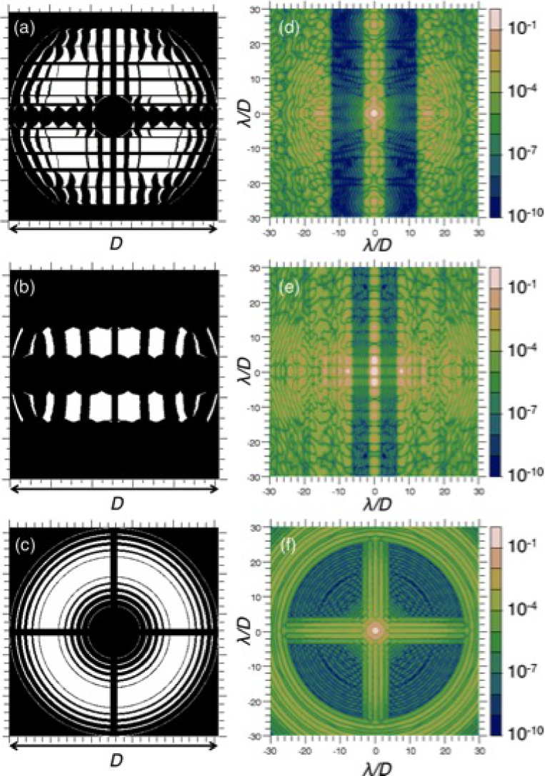
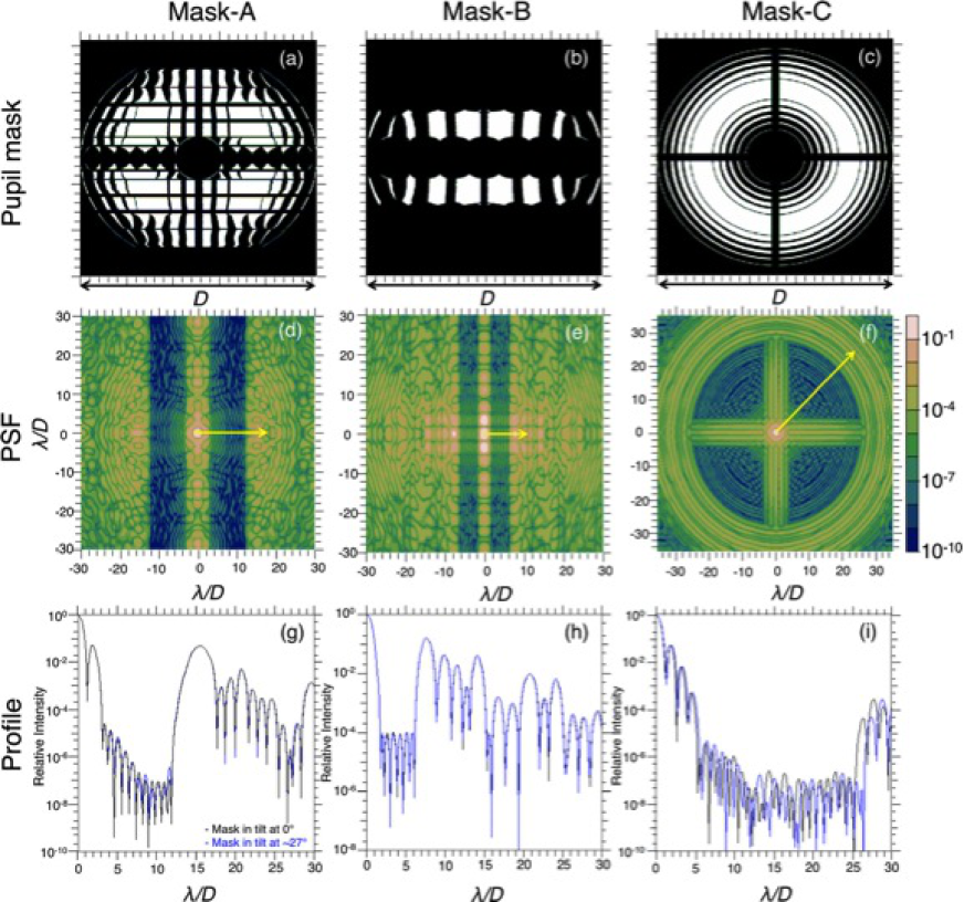
The designs of the masks (Mask-A, Mask-B, and Mask-C) are shown on the left-hand side of figure 1. These masks are types of binary shaped pupil masks, and their basic design is based on those reported in Enya et al. (2011b). Optimization of the basic mask shapes was performed with the LOQO solver presented by Vanderbei (1999). Mask-A and Mask-B are based on an integral 1D design, and Mask-C is based on a concentric ring design (table 1). These masks have the general advantages of binary pupil masks: (1) They are robust against pointing errors, and (2) they can, in principle, make observations over a wide range of wavelengths. These three masks also have a particularly important asset: (3) the design makes them applicable for the pupil of SPICA telescope, which is partially obscured by a secondary mirror and a support spider.
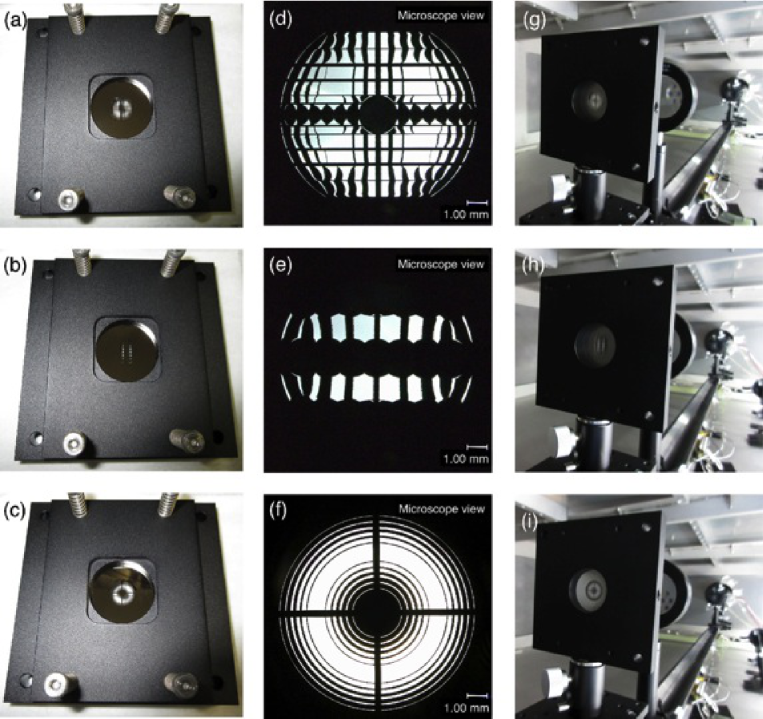
The theoretical PSFs of each mask are shown on the right-hand side of figure 1. The central bright region of the PSF is called the “core”, and the regions near to the core, in which diffracted light is reduced, are called the “Dark Regions (DRs)”. Mask-A is an example of a design with generalized darkness constraints. The inner working angle () and the outer working angle () are 3.3 and 12 , respectively, where is the wavelength and is the pupil diameter. The required contrast for this is at 3.3 and between 8 and 12 . The required contrast between 3.3 and 8 was determined by the constraint that the contrast should be below a straight line on a log scale. Mask-B is intended to be used with a small . The required contrast for this is between 1.7 and 6.2 . This mask is more useful than the other two masks for direct observation in the infrared wavelength region of young Jovian planets close to the star. With Mask-C a wide-field coronagraphic image is obtained. The and the are 5 , and 25 , respectively, and the contrast for this is at 5 and between 12 and 25 . The contrast between 5 λ/D and 12 λ/D was determined to be below a straight line on a log scale. This mask is useful for surveying unknown exoplanets far from the stars they orbit and for observations of diffuse targets such as circumstellar disks related to planetary formation in the infrared wavelength region. The masks were fabricated as free-standing masks, as shown in figure 2, and, consequently, can be used for infrared observations. These free-standing masks were fabricated in nickel using nano-fabrication technology at HOWA Sangyo Co., Ltd and Photo Precision Co., Ltd in Japan. The designs cover a 30 mm square, and comprise 10 mm mask patterns in thin nickel surrounded by thicker nickel borders designed to enable the masks to be easily handled. The target thicknesses of the patterned area and the handling area are 5 and 100 , respectively. First, nickel with a target thickness of 5 was grown by electrolytic plating on a temporary substrate. Then, the handling area with a target thickness of 100 was deposited by further electrolytic nickel plating. Finally, the free-standing mask was completed by stripping it from the temporary substrate. The fabrication process for the freestanding nickel masks is detailed in Enya et al. (2012).
The pattern of the basic design of Mask-A contained some isolated and/or ultra-fine features, which are not viable for a free-standing mask. Therefore, for Mask-A, we added bridge structures in a direction that had no effect on the contrast to support and link the isolated and/or ultrafine structures together. The fact that our mask design is based on a 1D coronagraph is an important advantage in that such bridge structures can in principle be applied (Enya et al., 2011b). Indeed, simulation showed that the contrast obtained with the amended masks was equivalent to the contrast obtained with masks with the basic design. On the other hand, Mask-C has long arches and fine features not shared by Mask-A and Mask-B (the width of the narrowest arch and the space between the arches were designed to be 33 and 20 , respectively). Because of this, we had the problem that the mask was irreversibly damaged during removal from the substrate. However, the problem was finally solved by small changes to the fabrication process conditions for Mask-C (i.e., the mask design was not changed) from the original fabrication process described in Enya et al. (2012).
2.2 Configuration of experiment
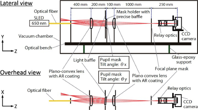
Figure 3 shows the instrument used for this work. All the experimental optics were located in a clean-room at the Japan Aerospace Exploration Agency/the Institute of Space and Astronautical Science (JAXA/ISAS). The coronagraph optics were set up in a vacuum chamber, an experimental platform we call the High dynamic range Optical Coronagraph Testbed (HOCT). We used a Super luminescent Light Emitting Diode (SLED) with a center wavelength of 650nm and wavelength width of 8 nm for the light source. Light was passed into the chamber through a singlemode optical fiber. The beam from the optical fiber was collimated by a 50 mm diameter BK7 plano-convex lens (SIGMA KOKI Co., Ltd.), and the collimated beam passing through the pupil mask was focused by a second planoconvex lens. The pupil mask was set at an angle of to the plane perpendicular to the optical axis to remove light reflected from the mask (see figure 3 for the definition of the coordinates and ). We used 3.4× relay optics after the focal plane. Multi-layer anti-reflection coatings optimized for wavelengths of 400 - 700 were applied to both sides of the lens to reduce reflection. Though active wavefront control helps to improve contrast, it was not applied in this work in order to evaluate the performance of the masks themselves. A commercially available cooled CCD camera (BJ-42L, BITRAN) with 20482048 pixels set up in the chamber was used to measure the PSF. The CCD was cooled and stabilized at . This experimental system is capable of achieving a raw contrast of (Haze et al., 2009, 2011; Haze, 2012; Enya et al., 2012).
To obtain a high-contrast image, we carried out the following procedure: we measured the core and the DR, each of which have different imaging times, separately.When the DR was measured, we obscured the light from the core with a focal plane mask (i.e., a DR-shaped hole mask) inserted at the first focal plane after the pupil mask. For measuring the core, we replaced the DR-shaped hole mask with two neutral density (ND) filters. The transmission through the ND filters is wavelength dependent, and at 650nm is 0.016%.
2.3 Core image
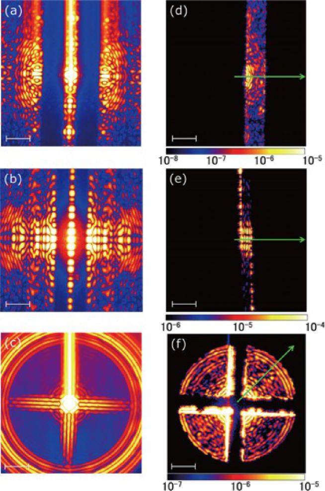
The core image of the coronagraphic PSF was obtained with exposure times of 0.3 s and 3 s. We inserted two ND filters as previously mentioned. After each imaging process, the laser source was turned off and a “dark frame” measurement was taken with the same exposure time and the same neutral density filters. A “raw” coronagraphic image was obtained by subtracting the dark frame from the image with the laser light on (see left-hand side of figure 4). These results are quite consistent with those expected from theory (see figure 1).
2.4 DR image
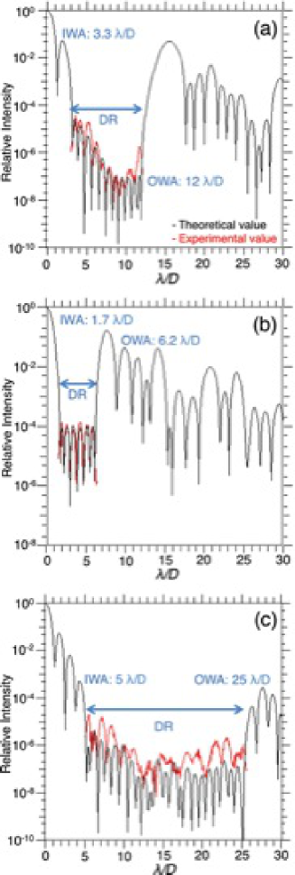
The DR of the coronagraphic image was observed with exposure times of 0.3 s, 3 s, and 30 s. A “dark frame” was taken with the same exposure times, and these were then subtracted from the DR images with the laser light on. The observed DRs of the raw coronagraphic image, which is the area of the image through the focal plane mask, are shown on the right-hand side of figure 4. The contrast was obtained by normalizing the observed DRs to the peak of the core.
As shown in figure 5a, contrasts of - and for the ranges of 3.3 - 8 and 8 - 12, respectively, were achieved using Mask-A. These experimental contrasts almost reached the designed values. The slightly poorer contrast near the is thought to be due to contamination from light outside the . As shown in figure 5b, a contrast of close to the center was achieved using Mask-B. The experimental contrast is almost the same as the designed value. As shown in figure 5c, a contrast of - over an extended field of view (5 - 25 ) was achieved using Mask-C. We also found speckle patterns other than diffraction patterns in the DRs. For example, the observed PSF of Mask-C, which has a contrast of between 20 and 23 , has two ring structures (see figures 4f and 5c).
3 Discussion
3.1 Merits of the new masks for actual observations
One of the critical issues for coronagraphy is preventing the pupil of the telescope from being obscured. So offaxis telescopes have been specifically designed for space missions specializing in coronagraphy—e.g., TPF-C (Traub et al., 2006); SEE-COAST (Schneider et al., 2006); PECO (Guyon et al., 2009). On the other hand, the masks developed in this study are designed for an on-axis telescope, in which the pupil is partially obscured by the secondary mirror and its supporting arms. The experiments with each of these masks described here show that the contrast is significantly improved compared with non-coronagraphic optics. These masks also have the properties of a binary pupil mask coronagraph in that they are robust against pointing errors and they can be used to make observations over a wide wavelength range. These masks have no limitation to the wavelength range over which they can be used because they are free-standing. Therefore, the application of these binary pupil mask coronagraphs to a number of different normal, centrally obscured telescopes can help to open up new platforms for coronagraphy. Many advanced ground-based telescopes (e.g., current 8 - 10m class telescopes like Subaru, and larger future ones such as TMT, E-ELT) and space telescopes (e.g., SPICA, JWST) with an obscured pupil have the potential to be platforms for coronagraphy over a wide wavelength region. The specifications of the masks developed in this study are complementary, and are, therefore, useful for observing Jovian planets located at various distances from the central star in the mid-IR wavelength region (Fukagawa, Itoh & Enya, 2009; Matsuo et al., 2011; Enya et al., 2011a). Obtaining the spectra of Jovian planets is invaluable if we wish to learn more about planetary formation processes. These complementary masks are also useful for studying protoplanetary disks and AGN.
3.2 The contrast obtained with Mask-C
Here, we consider the factors that limited the contrast obtained with the masks in the coronagraphic experiments. The experimental PSF using Mask-B agreed very well with the designed PSF. The experimental PSF using Mask-A matched the designed PSF most closely. On the other hand, forMask-C, the discrepancy in contrast between the design and the experiment is significantly larger than for both Mask-A and Mask-B. Moreover, the experimental PSF obtained withMask-C had two ring structures not expected from the design.
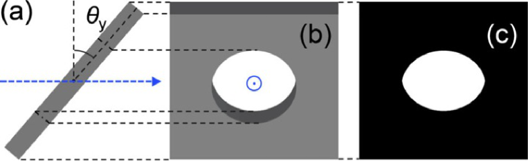
In the experiment described in the previous section, the pupilmaskwas set at an angle (, using the coordinate system defined in figure 3) to the plane perpendicular to the optical axis in order to eliminate light reflected by the mask. Thus, to enable further discussion of the contrast obtained from the experiment, we examined the effect of tilting the mask.
Using Cartesian coordinates, the x and y variables for the 1D coronagraph masks, Mask-A and Mask-B, can be separated, while those for Mask-C, which is rotationally symmetric, cannot. Qualitatively, this suggests that the contrast can be reduced from the optimum by tilting Mask-C. However, a quantitative assessment of the influence of the tilt on the contrast obtained with Mask-C has not yet been done.
Therefore, we assumed the masks to be ideally flat and, with a larger tilt angle (, using the coordinate system defined in figure 3), made projections that took account of the influence of the mask thickness of 5 , as shown in figure 6. The coronagraphic PSFs were obtained from simulation using Fourier transform techniques. The results are shown in figure 7. The simulation shows that a tilt angle of should not affect the contrast obtained not only with Mask-A and Mask-B but also with Mask-C.
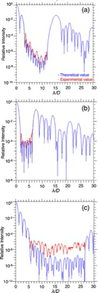
Consequently, we conducted additional experiments with the masks tilted at (see figure 3). A comparison between the results from experiment and those from simulation with the masks tilted at is shown in figure 8. With Mask-A and Mask-B the experimental results are almost consistent with the simulations. The slightly poorer contrast near the and the is thought to be due to the effect of light contamination from outside the and the .On the other hand, the experimental results using Mask-C show the contrast to be worse than that expected from the simulation. A deviation from perfect flatness of the mask is a possible reason for these results. Our freestanding masks were fabricated by stripping them from a substrate after forming them on the substrate. Indeed,many trials were needed to succeed in stripping off the long arches and fine structure of Mask-C without it breaking because the stripping process for Mask-C is fraught with more difficulty than for either Mask-A or Mask-B. To assess and possibly prevent the effects due to errors in flatness, comparative experiments with a similar mask on a substrate would be useful.
4 Conclusion
In this study, we have presented the fabrication and experimental demonstrations of free-standing coronagraphmasks with three complementary designs for telescopes, in which the pupil is partially obscured by a secondary mirror and its support structure. Coronagraphic images obtained from the experiments weremostly consistent with the design. The masks can be tilted with little effect on contrast, thereby giving us the freedom to choose the tilt angle to avoid ghosting and to manage stray light. The results are important for allowing general-purpose telescopes not specialized for coronagraphy to be used as platforms for high contrast coronagraphic observations in future.
Acknowledgement
First of all we are grateful to R. J. Vanderbei and the LOQO solver presented by him (Vanderbei, 1999). This work was financially supported by the Japan Science and Technology Agency and Grants-in- Aid for Scientific Research (Nos. 24840049 and 22244016) from the Japan Society for the Promotion of Science. We thank T. Ishii from Photo Precision Co., Ltd., A. Suenaga from HOWA Sangyo Co., Ltd, and their colleagues in each of these companies.
References
- Belikov et al. (2007) Belikov, R., et al. 2007, Proc. SPIE, 6693, 669328
- Carlotti et al. (2011) Carlotti, A., Vanderbei, R., Kasdin, N. J. 2011, arXiv: 1108.4050
- Enya et al. (2011a) Enya, K., et al. 2011a, Adv. Space Res., 48, 323
- Enya & Abe (2010) Enya, K., Abe, L. 2010, PASJ, 62, 1407
- Enya et al. (2011b) Enya, K., Abe, L., Takeuchi, S., Kotani, T., & Yamamuro, T. 2011b, Proc. of SPIE, 8146, 81460Q
- Enya et al. (2008) Enya, K., Abe, L., Tanaka, S, Nakagawa, T., Haze, K., Sato, T., & Wakayama, T. 2008, A&A, 480, 899
- Enya et al. (2012) Enya, K., Haze, K., Kotani, T., Abe, L. 2012, PASJ, 64, 123
- Enya et al. (2007) Enya, K., Tanaka, S., Abe, L., & Nakagawa, T. 2007, A&A, 461, 783
- Fukagawa, Itoh & Enya (2009) Fukagawa, M., Itoh, Y., Enya, K. 2009, Proc. of SPICA joint European/Japanese Workshop, p.02006
- Guyon et al. (2009) Guyon, O., et al. 2009, Proc. SPIE, 7440, 74400F
- Haze (2012) Haze, K. 2012, Ph.D. thesis, The Graduate University for Advanced Studies
- Haze et al. (2011) Haze, K., Enya, K., Abe, L., Kotani, T., Nakagawa, T., Sato, T., & Yamamuro, T. 2011, PASJ, 63, 873
- Haze et al. (2009) Haze, K., Enya, K., Abe, L., Tanaka, S., Nakagawa, T., Sato, T., Wakayama, T., & Yamamuro, T. 2009, Adv. Space Res., 43, 181
- Jacquinot & Roizen-Dossier (1964) Jacquinot, P., & Roizen-Dossier, B. 1964, Prog. Opt., 3, 29
- Kasdin et al. (2005a) Kasdin, N. J., Belikov, R., Beall, J., Vanderbei, R. J., Littman, M. G., Carr, M., & Give’on, A. 2005a, Proc. SPIE, 5905, 128
- Kasdin et al. (2005b) Kasdin, N. J., Vanderbei, R. J., Littman, M. G., & Spergel, D. N. 2005b, Appl. Opt., 44, 1117
- Matsuo et al. (2011) Matsuo, T., Fukagawa, M., Kotani, T., Itoh, Y., Tamura, M., Nakagawa, T., & Enya, K. 2011, Adv. Space Res., 47, 1455
- Schneider et al. (2006) Schneider, J., et al. 2006, in Proc. Annual Meeting of the French Soc. Astron. and Astrophys., ed. D. Barret et al. (Montpellier: Universit´e Montpellier), 429
- Spergel (2001) Spergel, D. N. 2001, astro-ph/0101142
- Tanaka et al. (2006) Tanaka, S., Enya, K., Abe, L., Nakagawa, T., & Kataza, H. 2006, PASJ, 58, 627
- Traub et al. (2006) Traub, W. A., et al. 2006, Proc. SPIE, 6268, 62680T
- Traub & Jucks (2002) Traub, W. A., & Jucks, K. W. 2002, astro-ph/0205369
- Vanderbei (1999) Vanderbei, R. J. 1999, Optimization methods & software, 11, 485
- Vanderbei et al. (2004) Vanderbei, R. J., Kasdin, N. J., & Spergel, D. N. 2004, ApJ, 615, 555
- Vanderbei et al. (2003a) Vanderbei, R. J., Spergel, D. N., & Kasdin, N. J. 2003a, ApJ, 590, 593
- Vanderbei et al. (2003b) Vanderbei, R. J., Spergel, D. N., & Kasdin, N. J. 2003b, ApJ, 599, 686
| Mask (type) | Separation angle ∗∗\ast∗∗\astSeparation angle for integral 1D mask is defined from the PSF core to the coronagraphic direction. | Contrast |
| (λ/D) | ||
| Mask-A (integral 1D) | 3.3 ††\dagger††\dagger of the mask design (see text). | |
| 8.0 | ||
| 12 ‡‡\ddagger‡‡\ddagger of the mask design (see text). | ||
| Mask-B (integral 1D) | 1.7 ††\dagger††\dagger of the mask design (see text). | |
| 6.2 ‡‡\ddagger‡‡\ddagger of the mask design (see text). | ||
| Mask-C (ring) | 5.0 ††\dagger††\dagger of the mask design (see text). | |
| 12 | ||
| 25 ‡‡\ddagger‡‡\ddagger of the mask design (see text). |