Physically Unclonable Function using Initial Waveform of Ring Oscillators
Abstract
A silicon physically unclonable function (PUF) is considered to be one of the key security system solutions for local devices in an era in which the internet is pervasive. Among many proposals, a PUF using ring oscillators (RO-PUF) has the advantage of easy application to FPGA. In the conventional RO-PUF, frequency difference between two ROs is used as one bit of ID. Thus, in order to obtain an ID of long bit length, the corresponding number of RO pairs are required and consequently power consumption is large, leading to difficulty in implementing RO-PUF in local devices. Here, we provide a RO-PUF using the initial waveform of the ROs. Because a waveform constitutes a part of the ID, the number of ROs is greatly reduced and the time needed to generate the ID is finished in a couple of system clocks. We also propose a solution to a change of PUF performance attributable to temperature or voltage change.
I Introduction
In order to connect a huge number of devices as an Internet of Things (IoT), individual devices have to be manufactured at low cost. In addition, to protect personal information, a stable security system must be implemented. A physically unclonable function(PUF) is considered to be one of the important mechanisms for providing a unique ID for each device at low cost. A PUF outputs a response ID to a challenge signal. The origins of the PUF signal come from process variations of transistors and circuits. Many types of PUF have been already proposed. An arbiter PUF that uses the circuit delay is the most intensively investigated arbiter ; Lee . An SRAM-PUF that uses the initial memory value of SRAM is considered the most advanced Guajardo ; Holcomb . Altera has announced its intention to implement an SRAM-PUF unit in the company’s high-end FPGA. Initial defects of memories Marukame ; RRAM or trap sites in the transistor Chen can be also used to constitute a PUF. The first PUF based on ring oscillators (RO-PUF) was presented by Suh et al. Suh , in which the frequency difference between two ROs is used as the PUF output. The RO-PUF has an advantage in that it can be implemented in commercial FPGAs without difficulty and the stability is proved Maiti0 . However, previous RO-PUFs using the frequency difference between RO pairs have disadvantages: the number of RO pairs corresponds to the length of the ID, resulting that a large number of ROs is required. Thus, from viewpoint of IoT which requires low-power other than low-cost, continuous running of RO of conventional RO-PUF is not desirable.
Because FPGAs are widely used as the basic tools to implement designs, FPGA-based PUFs are expected to protect the individual properties. Here we propose a PUF based on a ring oscillator (RO) using the initial waveform of the RO output just after the oscillation starts. We use an RO pair in which one RO is used for sampling of the other RO. Because the frequency of RO ( 1 GHz) is much faster than the system clock ( 50-100 MHz), the sampling process is finished within a couple of cycles of the system clock, resulting in fast ID generation and low power consumption. We tested our idea on Altera Cyclone V (28nm), and Xilinx (Spartan-6 and Spartan-3E) devices. Our PUF is flexible because there is no design constraint. We use a simple Verilog circuit.
The rest of the paper is organized as follows. In section II, we discuss related works regarding the RO-PUF. In section III, we present our RO-PUF using a starting wave of the RO output. Experimental details and results are presented in section IV. Section V is devoted to the performance evaluation of the proposed PUF. In section VI, we discuss temperature dependence. Section VII presents conclusions.
II Related works
The mechanism of previous proposed RO-PUFs involves comparing frequencies between two ROs, and the large frequency variance leads to robustness of RO-PUFs. In the first proposal of an RO-PUF Suh the best RO pair with large frequency difference is selected out of many ROs, resulting in the requirement of a large number of ROs. Maiti et al. found that the RO frequency depends on the location on the FPGA, and improved the reliability of an RO-PUF by implementing each RO in one configurable logic block Maiti1 . Merli et al. show a chain-like structure that enhances the frequency difference using the frequency difference of nearest neighbor ROs Merli . Habib et al. proposed a more efficient RO-PUF by considering the programmable delay lines Habib .
There are many proposals regarding PUFs based on FPGA other than RO-PUFs. Tuyls et al. proposed the butterfly-PUF butterfly and Flip-Flop(FF)-PUF FF-PUF . The butterfly-PUF shows excellent performance of the Hamming distance and small temperature dependence. The butterfly-PUF uses a bistable state of two FFs and is an FPGA version of the SRAM-PUF. Although the butterfly-PUF shows excellent PUF performance, precise symmetry is required in the bistable FF structure. Yamamoto et al. proposed a PUF using RS-FF Yamamoto in which inhibition input of RS-FF is used to reflect the chip identity. These PUFs require routing constraints or hard macro, resulting in lack of generality in the conventional use of FPGA, in which various applications and IPs are implemented at low cost.
The RO-PUF presented here requires neither routing constraint nor hard macro. Circuits automatically implemented by FPGA software are measured in three kinds of FPGA devices. Various PUF performances are estimated.
III Proposed PUF using waveform of ROs
The origin of a PUF is the process variation of transistors and circuits, and the previously proposed RO-PUFs show that the process variations appear in the frequency of ROs. The frequency difference among different ROs means that the period of one cycle between rising edges differs depending on each RO. Thus, it is natural to consider that the waveform difference of an RO can be used as the source of a PUF. The RO begins to oscillate when the supply voltage is applied or the enable switch is on. When the initial output value of the RO is 0, the time to first rising edge of oscillation signals differs depending on each RO.
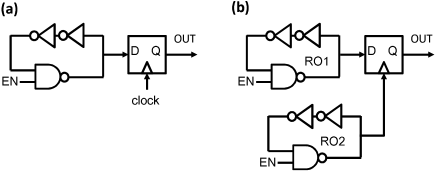
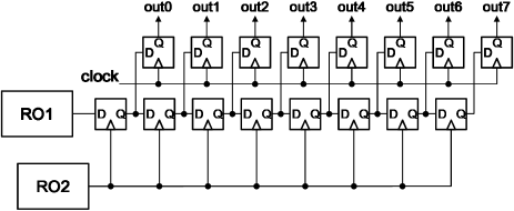
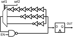
However, because the frequency of ROs ( 1 GHz) is much higher than the clock frequency of the conventional circuit board ( 50-100 MHz), the conventional RO set up shown in Fig.1 (a) is insufficient to capture the oscillation signal. In order to capture the oscillation signal of the RO at higher time resolution, we use other ROs as the sampling clock of FF. Figure 1(b) is the minimum unit of the proposed PUF using the waveform of ROs (wRO-PUF). Because the output frequency of Fig.1(b) is still high, we need FFs to convert the higher-frequency signals to the lower-frequency digital data used in the other circuit. Figure 2 is the basic unit of the wRO-PUF, where the number of FFs corresponds to the length of generated ID for this element.
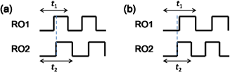
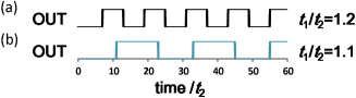
Let us analyze the waveform of Fig.1(b). Figure 3 shows the two possible patterns of the initial waveforms of the two ROs. When , the ROs start to oscillate, and the initial value of ROs is set to 0 by the NAND element in Fig.1(b). The time to the first rising edge differs depending on ROs. When the period of the waveform of RO1 is longer than that of RO2 (), the initial value of the output in Fig.1(b) is 0. When , the initial value of the output in Fig.1(b) is 1. The variation of the oscillation period depends on the properties of the transistors included in the ROs. Thus this mechanism resembles that of the conventional RO-PUFs. Moreover, because the waveforms are analog data, the relative difference between two waveforms is the origin of new degrees of freedom when they are digitized. Figure 4 shows an example where the output signal (OUT) pattern of wRO-PUF greatly changes depending on the relative change even when we limit . If we take the first 32bits from these output signals, the number of the different bits between the two signals is 13, which corresponds to the Hamming distance of the two data.
We consider that the device ID of FPGA consists of outputs of several RO pairs in Fig. 2. Thus, the number of the FFs in Fig. 2 corresponds to the length of a unit ID component. Because the frequency of RO is very high, it is considered that the sampling by ROs is out of the conventional operational region of FFs. In particular, the change of signal in terminal is compatible with terminal, resulting in the difference of output depending on the chip. In addition, the output of Fig. 2 is considered to be affected by the wire delay between the output of RO2 and FFs. This effect changes the periodic waveform to partly aperiodic waveform. This mechanism resembles the arbiter-PUF or FF-PUF. Thus, our wRO-PUF generates ID from the causes of RO-PUF (transistor variation) and the arbiter-PUF(circuit variation).
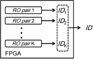
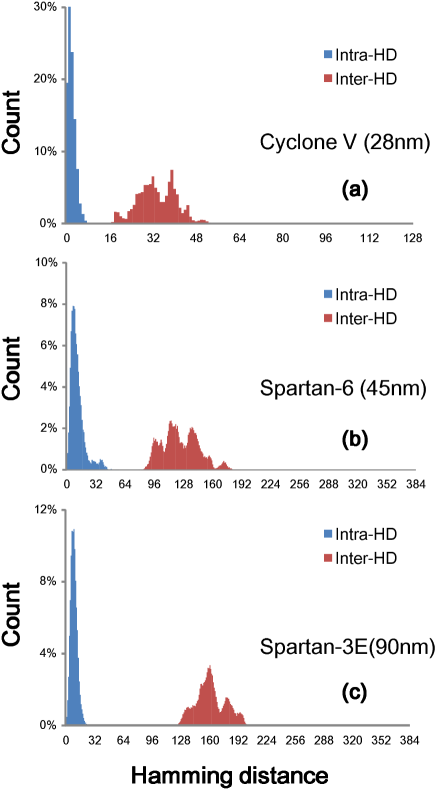
TABLE I
Details of the datasets used.
| Cyclone V | Spartan-6 | Spartan-3E | |
| :Number of devices | 11 | 11 | 10 |
| : Number of RO pairs | 8 | 12 | 12 |
| length from one RO pair | 16 | 32 | 32 |
| : Number of tests per ID | 1000 | 1000 | 1000 |
| System clock | 100 MHz | 50 MHz | 50 MHz |
IV Experiments
We apply our PUF to Xilinx Spartan-3E (xc6slx16-3csg324, Nexys2) and Spartan-6 (xc3s500e-4fg320, Nexys3) and Altera Cyclone V GX (5CGXFC5C6F27C7N, Terasic). ID is determined by the pattern of the wRO-PUF output that appears most frequently. We described the circuit of Fig.2 by Verilog and used Nios II and Microblaze to control the communication between the FPGA devices and our personal computer (Table I). No design constraint is included. Sampling is carried out by repeating and , where the ID of the RO pair is the initial continuous -bits after .
Examples of the measured waveforms of the five ROs of Spartan-6 are given by
The waveforms of the five ROs show different bit patterns after the automatic placement and routing reflecting the difference in the RO frequencies depending on their positions Maiti0 . It can be seen that the waveforms include some irregular bit patterns that are not inferred from the Fig. 5. These irregular bit patterns are considered to be the results of wiring delay variances of the many-FF chains in Fig.2.
The waveform after a long-time oscillation is affected by environmental noise. Thus, long ID generation is undesirable and it is better to produce a long ID by combining outputs of several RO pairs. We define the ID of each device by the combination of output ID of RO pairs of the device as illustrated in Fig. 5. That is, when the output sequence of -th RO pair defines , the total ID of the device is given by
| (1) |
The total ID length, , is given by .
The most important metric to estimate a PUF performance is the Hamming distance (HD), which is the number of different bits between two outputs. The waveform data are obtained by repeating the process of and . Here, the ID is defined as the pattern that appears most frequently over experimental data. The intra-chip HD is the HD between the ID and all sampled data in the same chip after repeated measurements. The count of the intra-HD ideally has a peak at zero HD. The inter-chip HD is defined by the HD between different chips, and is ideally distributed around half of the ID length. Figure 6 shows HDs for the experimental results of the three kinds of FPGAs. It is seen that the intra-HDs are distributed around their most frequent ID patterns. The peaks of the inter-chip HDs in Fig. 6 are smaller than the half of the ID length. The gap between the peak of the intra-HDs and those of the inter-chip HDs becomes smaller as the transistor size decreases. This gap is smallest for the Cyclone V FPGA. As mentioned above, the PUF properties of our wRO-PUF originate from the variations of RO frequency and wiring delay. As the technology node shrinks, the parasitic capacitance of the wiring is reduced, resulting in the decrease of delay variances. It is considered that the reducing variations of the wire delay reduces the gap between the intra-HDs and the inter-HDs.
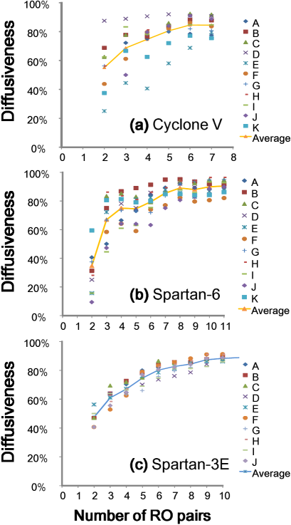
The ID distribution over many RO pairs can be measured by the diffusiveness introduced by Hori et al. Hori :
| (2) |
where is the -th binary bit of an -bit response from a chip . This quantity evaluates the degree of the difference among outputs of different RO pairs in the same device. The ideal value of the diffusiveness is 100% in which all the bit sequences from different IDs are different. Figure 7 shows the diffusiveness as the function of the number of RO pairs in the three types of FPGAs. The results of Fig. 7 show that combination of many RO pairs increases the quality of IDs.
The RO frequency can be adjusted by inserting buffers in the RO as shown in Fig. 8. Here, the buffers represent the primitive look-up tables (LUTs) prepared by Altera and Xilinx. It is found that the number of buffers slightly changes the ID in the present case of the automatic routing and placement.
TABLE II
PUF performance measured on the three types of devices.
| Cyclone V | Spartan-6 | Spartan-3E | Ideal Value | |
|---|---|---|---|---|
| Uniformity | 43.54 % | 55.66 % | 46.74 % | 50% |
| Reliability | 98.59 % | 96.96 % | 97.65 % | 100 % |
| Uniqueness | 62.00% | 32.52% | 42.20% | 100 % |
V PUF performance evaluation
We evaluate the PUF performance of our wRO-PUF based on the metrics discussed in Ref.Maiti3 ; Hori . The results of the evaluation are shown in Table II. Here, uniqueness is calculated from
| (3) |
where is the number of the tested devices, is the length of the ID, and is the ID pattern that appears most frequently. Reliability is calculated from
| (4) |
where is the number of times sampling is done. Uniformity is calculated from
| (5) |
The average results over all samples are listed in Table II.
The uniformity and the reliability are close to the desirable values, whereas the uniqueness is smaller than the ideal value. When we see that the arbiter-PUF shows smaller values of the uniqueness from Ref.Maiti3 ; Hori , the small value of the uniqueness is considered to come from the arbiter-PUF performance, because our PUF is a combination of the RO-PUF and the arbiter-PUF.
VI Temperature and voltage compensations
In general, as the temperature rises, RO frequency linearly decreases. Similarly, the change of supplied voltage affects the PUF outputs. In order to use RO-PUF, we have to take into account the effects of these environmental changes. The general solution to the changing ID is to add some feedback circuit to the PUF system Yang . However, for the low-cost PUF and FPGA-PUF, an analog circuit is not preferable.
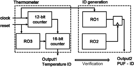
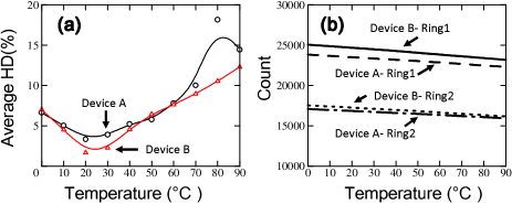
The simple solution to this problem is to detect the environmental change and provide IDs that also change according to the environment. Figure 9 shows our proposed circuit. We prepare the 3rd RO, RO3, whose frequency is estimated by a counter and shows the status of the environment Sayed . Figure 10(a) shows the average HD from the ID at 20 ∘C in the case of sampling done more than thousand times. As can be seen, the ID tends to change linearly as the temperature difference from 20 ∘C increases. The small temperature change would be correctable by an error-correcting code. Figure 10(b) shows the count of the RO3 in Fig. 9. It can be seen that the count has clear linear dependence on the temperature. When the RO3 is closely placed near the wRO-PUF, the change of the physical environment of wRO-PUF is correctly detected by the count of the RO3. Thus, in our scheme, by collating the count of RO3 (temperature ID) to the PUF-ID, we can check the correct ID of the device.
VII Conclusion
We proposed a RO-PUF using the initial waveform (wRO-PUF) accompanied by a temperature detection system that is also constituted by ROs. Although it is preferable that PUF units are placed compactly in the small area of the FPGA cell to avoid extra noises by the global wires in the FPGAs, the wRO-PUF is implemented just by downloading a Verilog circuit, without any manual routing. We proved the wRO-PUF is applicable to various FPGAs of Altera and Xilinx.
Acknowledgment
TT thanks A. Nishiyama, K. Muraoka, S. Shimizu, Y. Komano, T. Marukame, H. Noguchi, T. Kanesige, T. Ootuki, T. Yamakawa, and N. Sakamoto for useful discussion.
References
- (1) D. Lim, J. Lee, B. Gassend, G. Suh, M. van Dijk, and S. Devadas, “Extracting secret keys from integrated circuits,” IEEE Trans. Very Large Scale Integr. (VLSI) Syst., vol. 13, no. 10, pp. 1200-1205, Oct. 2005.
- (2) J.W. Lee, D. Lim, B. Gassend, G.E. Suh, M. van Dijk, S. Devadas, “A Technique to Build a Secret Key in Integrated Circuits for Identification and Authentication Application”, in Proc. Symp. VLSI Circuits, 2004, pp. 176-159.
- (3) J. Guajardo, S. S. Kumar, G.-J. Schrijen, and P. Tuyls, “FPGA intrinsic PUFs and their use for IP protection”, in Proc. 9th Int. Workshop on Cryptographic Hardware and Embedded Systems (CHES’07), 2007, pp. 63-80.
- (4) D. E. Holcomb, W. P. Burleson, and K. Fu, “Power-up SRAM State as an Identifying Fingerprint and Source of True Random Numbers”, IEEE Trans. Comput., vol. 58, no. 9, pp. 1198-120, Sep. 2009.
- (5) T. Marukame, T. Tanamoto, and Y. Mitani, “Extracting Physically Unclonable Function From Spin Transfer Switching Characteristics in Magnetic Tunnel Junctions”, IEEE Trans. Mag. vol. 50, no. 11, pp.1-4, Nov. 2014.
- (6) A. Chen, “Utilizing the Variability of Resistive Random Access Memory to Implement Reconfigurable Physical Unclonable Function”, IEEE Elec. Dev. Lett. vol. 36, no.2 pp. 138-140, Feb. 2015.
- (7) J. Chen, T. Tanamoto, H. Noguchi, and Y. Mitani, “Further investigations on traps stabilities in random telegraph signal noise and the application to a novel concept physical unclonable function (PUF) with robust reliabilities”, 2015 IEEE Symp. VLSI Tech. 2015, pp.40-41.
- (8) G. E. Suh and S. Devadas, “Physical unclonable functions for device authentication and secret key generation”, in Proc. 44th Ann. Design Automation Conf. (DAC’07), 2007, pp. 9-14.
- (9) A. Maiti, J. Casarona, L. McHale, and P. Schaumont, “A large scale characterization of RO-PUF”, in Proc. IEEE Int. Symp. 2010 Hardware- Oriented Security and Trust (HOST), 2010, pp. 94-99.
- (10) A. Maiti and P. Schaumont, “Improving the quality of a physical unclonable function using configurable ring oscillators”, In 19th International Conference on Field Programmable Logic and Applications 2009 (FPL ’09), 2009, pp 703-707.
- (11) B. Habib , K. Gaj, J.-P. Kaps, “FPGA PUF Based on Programmable LUT Delays”, in Proc. Euromicro Conf. Digital System Design 2013 (DSD’13) 2013, pp 697-704.
- (12) D. Merli, F. Stumpf, and C. Eckert, “Improving the quality of ring oscillator PUFs on FPGAs”, in Proc. 5th Workshop on Embedded Systems Security(WESS’ 10), 2010.
- (13) S. Kumar, J. Guajardo, R. Maes, G.-J. Schrijen, and P. Tuyls, “Extended abstract: The butterfly puf protecting IP on every FPGA”, in Proc. IEEE Int. Workshop on Hardware-Oriented Security and Trust, 2008 (HOST 2008), 2008, pp. 67-70.
- (14) R. Maes, P. Tuyls, I. Verbauwhede, “Intrinsic PUFs from flip-flops on reconfigurable devices”, in Proc. Workshop on Information and System Security (WISSec). 2008, pp. 17-26.
- (15) D. Yamamoto, K. Sakiyama, M. Iwamoto, K. Ohta, T. Ochiai, M. Takenaka, and K. Itoh, “Uniqueness enhancement of puf responses based on the locations of random outputting rs latches”, in Proc. 13th Int. Workshop on Cryptographic Hardware and Embedded Systems (CHES’11), 2011, pp. 390-406.
- (16) A Maiti, and P. Schaumont, “The Impact of Aging on a Physical Unclonable Function”, IEEE Trans. Very Large Scale Integr. (VLSI) Syst, vol 22, no.9, Sept. pp.1854-1864 (2013).
- (17) Y. Hori, T. Yoshida, T. Katashita, and A. Satoh, “Quantitative and statistical performance evaluation of arbiter physical unclonable functions on FPGAs”, in Proc. 2010 IEEE Int. Conf. Reconfigurable Computing and FPGAs (ReConFig2010) pp. 298-303.
- (18) K. Yang, Q. Dong, D. Blaauw, and D. Sylvester, “A Physically Unclonable Function with BER for Robust Chip Authentication Using Oscillator Collapse in 40nm CMOS”, IEEE Int. Solid-State Circuits Conference 2015, pp 254-255.
- (19) M. A. Sayed, and P. H. Jones, “Characterizing non-Ideal Impacts of Reconfigurable Hardware Workloads on Ring Oscillator-based Thermometers”,in Proc. 2011 IEEE Int. Conf. Reconfigurable Computing and FPGAs (ReConFig2011), 2011, pp. 92-98.