Study of Relay Selection for Physical-Layer Security in Buffer-Aided Relay Networks Based on the Secrecy Rate Criterion
Abstract
In this paper, we investigate an opportunistic relay and jammer scheme along with relay selection algorithms based on the secrecy rate criterion in multiple-input multiple-output buffer-aided down link relay networks, which consist of one source, a number of relay nodes, legitimate users and eavesdroppers, with the constraints of physical layer security. The opportunistic relay and jammer scheme is employed to improve the transmission rate and different relay selection policies are performed to achieve better secrecy rate with the consideration of eavesdroppers. Among all the investigated relay selection policies, a relay selection policy which is developed to maximize the secrecy rate based on exhaustive searches outperforms other relay selection policies in terms of secrecy rate. Based on the secrecy rate criterion, we develop a relay selection algorithm without knowledge of the channels of the eavesdroppers. We also devise a greedy search algorithm based on the secrecy rate criterion to reduce the computational complexity of the exhaustive search technique. Simulations show the superiority of the secrecy rate criterion over competing approaches.
Index Terms:
Physical layer security, relay selection, buffer relay systemsI Introduction
Secure transmission is difficult to achieve in broadcast channels due to the nature of wireless communications. Traditional encryption techniques are implemented in the network layer with complex algorithms and high cost. To reduce such cost, researchers are exploring novel security techniques in the physical layer. Physical-layer security has been first illustrated by Shannon using an information theoretic viewpoint [1]. The feasibility of physical-layer security has been discussed by Shannon in a theoretical level in [1]. Later on in [2] a wire-tap channel, which can achieve positive secrecy rate, has been proposed by Wyner under the assumption that the users have a better statistical channel than eavesdroppers. Since then further research has been devoted to the wire-tap model and techniques such as broadcast channels [3], MIMO channels, artificial noise, beamforming as well as relay techniques. This paper focuses on relay techniques.
Recently, the concept of physical-layer security with multiuser wireless networks has been investigated [4]. Relay systems are an important evolution of secure transmission strategies and techniques to further improve the performance of relay systems such as relay selection [5] and buffer-aided relay nodes [6] are drawing significant attention. Opportunistic relay schemes have been applied to buffer-aided systems [7], [8] and [9]. In opportunistic relay schemes, the inter-relay interference (IRI) is an important aspect that should be taken into account.
In our previous work [10], we have introduced an opportunistic relay and jammer scheme and investigated its potential for improving secrecy rate. In this work, we employ the same scheme and focus our research on different relay selection algorithms [11, 12, 13, 14, 15]. Unlike prior art which relies on the signal-to-interference-plus-noise (SINR) and channel state information [16] approaches, we examine the potential of using the secrecy rate as the criterion for the selection of relays. In particular, a relay selection strategy is developed to maximize the secrecy rate based on exhaustive searches. A greedy search algorithm is then developed to reduce the computational complexity of the exhaustive search approach.
This paper is organized as follows. Section II details the system model, describes the opportunistic relay and jammer buffer-aided relay system. We focus on the transmission from the source to the relays and from the relays to the users. Section III presents all investigated conventional as well as the proposed relay selection criterion, whereas Section IV details the proposed secrecy rate based criterion with partial channel information. Section V shows and discusses the numerical results, while the conclusions are drawn in Section VI.
II System Model and Performance Metrics
In this section, a brief introduction of the buffer-aided relay system model is given to describe the data transmission. The performance metrics illustrate the assessment of the proposed and existing techniques described in this paper.
II-A System Model

Fig. 1 gives a description of a source node with antennas that transmits the data streams to users in the presence of eavesdroppers. With relays and jammers, in each time slot, the selected relays will receive signals from both the source and the jammers. Each relay and jammer is equipped with and antennas. At the receiver side each user and eavesdropper is equipped with and receive antennas. The quantities and denote the channel matrices of the th relay and the th eavesdropper, respectively. The quantities and denote the channel matrices of the th eavesdropper to the th jammer and the th user to the th jammer, respectively. The channel between the th relay to the th relay is modeled by . To support users transmission, the source is equipped with antennas.
The vector represents the data symbols to be transmitted corresponding to each user in time slot . The total transmit signal at the transmitter can be expressed as
| (1) |
In prior work, several precoding techniques have been considered to eliminate the interference between different users [17, 18, 19, 20, 21, 22]. Alternative approaches to the computation of the transmit filters can be employed [23, 24, 25, 26, 27, 28, 29, 30, 31, 32, 33, 34, 35, 36, 37, song, locsme].. In this work, we use linear zero-forcing precoding and the precoding matrix is described by
| (2) |
The channels of the selected jammers to the th user are given by
| (3) |
The channels of the jammers to the th relay channel are
| (4) |
To simplify the calculation, we assume that each relay will have the same antenna as each user which means . In each phase, the received signal at each relay node can be expressed as:
| (5) |
In (5), the value represents the previous time slot when the signal is stored as a jamming signal in the buffer at the relay nodes. The term is regarded as the inter-relay interference (IRI) between the th relay and jammers and is determined as the jamming signal according to a SINR criterion as in [7]. With the theorem in [7], the IRI can be eliminated.
The channel of the jammers to the th eavesdropper is described by
| (6) |
The received signal at the eth eavesdropper is given by
| (7) |
For the eavesdropper, the term acts as the jamming signal and this jamming signal can not be removed without the knowledge of the channel from the kth jammer to the eth eavesdropper.
In (5) and (7), the IRI term between the relay nodes or the jamming signal to the eavesdropper is simultaneously the transmit signal from the relays nodes to the destination. We assume that the transmit signal from the relay nodes is given by
| (8) |
Note that represents the previous time slot and due to the characteristics of buffer relay nodes, the values can be different for each relay node. The received signal at the destination can be expressed as:
| (9) |
Advanced detection techniques can be used to improve the quality of the reception [38, 39, 31, 40]
III Selection with Jamming Function Relays in Multiuser MIMO Buffer-aided Relay System
In this section, a novel selection approach with jamming function relays is introduced. We first consider a simple single-antenna scenario and then the selection approach is extended to a MIMO scenario. After that, a further exploration of the relay selection in a multiuser MIMO buffer-aided relay system is undertaken.
III-A Relay Selection Criteria
III-A1 Conventional Relay Selection Criterion
The conventional selection relies only on the knowledge of channel information between the source to the relays and the relays to the users. In [41], a max-min relay selection is considered as the optimal selection scheme for conventional decode-and-forward (DF) relay setups. With a single-antenna scenario the relay selection policy is given as:
| (10) |
where is the link between the source to the relay and is the relay to the destination.
With the consideration of the eavesdropper, a max-ratio selection policy is proposed in [17] and given by
| (11) |
with
| (12) |
| (13) |
The aforementioned relay selection are based on the channel state information. In [16] there is also a conventional selection as well as optimal selection based on the SINR criterion.
III-A2 Maximum Likelihood (ML) Relay Selection Criterion
Based on the conventional relay selection criterion, we substitute the channel state information with the ML rule which can be expressed as:
| (14) |
with
| (15) |
| (16) |
the ML relay selection selects the relay which gives the minimum ML rule value.
III-A3 Secrecy Rate Based Relay Selection Criterion
Similar to the ML relay selection criterion, the secrecy rate (SR) relay selection criterion is proposed to achieve better secrecy rate performance. The selection procedure can be expressed as:
| (17) |
with
| (18) |
| (19) |
Based on the single-antenna scenario, the criterion for MIMO system is given by
| (20) |
where is given as:
| (21) |
and
| (22) |
where
| (23) |
III-A4 Proposed Secrecy Rate Based Relay Selection Criterion without Knowledge of Eavesdroppers
Based on (5) and (7), the covariance matrix of the interference and the signal can be obtained as and . When the matrices are square and have equal size we can obtain the proposed secrecy rate based relay selection criterion as described by
| (24) |
which can be achieved without knowledge of the channels of the eavesdroppers. The details of the derivation of the above expression is given in Section IV.
III-B Greedy Algorithm in Relay Selection
When the relay selection criterion is determined, we will give an example using the greedy search algorithm. Here we choose relays according to the SR criterion. When the relays that forward the signals to the users are selected, the relays used for signal reception are chosen based on the SR criterion, as given by
| (25) |
where represents the selected relays and is the SINR corresponding to the th relay which is given by
| (26) |
where
| (27) |
with the SINR calculated for the th eavesdropper described by
| (28) |
where
| (29) |
and
| (30) |
The main steps are described in Algorithm 1.
IV Relay Selection Criterion Analysis
The details of the conventional relay selection criterion, ML relay selection criterion as well as the secrecy rate-based relay selection criterion have been introduced in Section III. Following this, here we will mainly focus on the proposed secrecy rate based relay selection criterion with partial channel information. To simplify the derivation, in the following formulas, we did not take interference from jammers into consideration and we take the transmission from the source to the relay as an example. Therefore, we have
| (31) |
and
| (32) |
From the original expression for the MIMO secrecy rate performance and our system structure, we can write the expression as
| (33) |
Since the maximization of the of an argument is equivalent to the maximization of the argument (33) can be simplified to
| (34) |
Similarly to the max-ratio criterion expressed in [17], in order to release the assumption of eavesdroppers channel, instead of (34) we consider the following criterion:
| (35) |
which can be rewritten as
| (36) |
Using linear algebra properties and by further manipulation, we arrive at
| (37) |
If and only if the matrices are square and have equal size, we can write
| (38) |
In the above expression, the determinant of the channels of the eavesdroppers can be eliminated, resulting in
| (39) |
By adding the to (39), we obtain
| (40) |
which is equivalent to (24). Here we have the results for equal size channels. When the channels have different sizes we can add zero elements into the channel matrix and we can still obtain the same result as equal size channels.
V Simulation Results
In the simulation of the multiuser MIMO scenario, the transmitter is equipped with antennas and each relay node is equipped with antennas for receiving or transmitting signals. Each user is equipped with antennas and the number of users is set to . In this scenario, eavesdroppers equipped with antennas each are also considered in the system. In order to mitigate the interference, a zero-forcing precoding technique is implemented at the source and also at the relays. To simplify the transmission scenario, in the selection we assume the number of selected relays and jammers are the same, which means we have . In all the simulations, all the channels are generated as flat-fading channel.
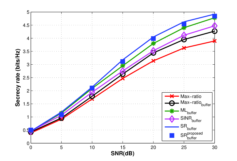
In Fig. 2, different relay selection criteria are compared in a single-antenna scenario. The secrecy rate performance has an improvement if buffers are employed in the relay nodes. Among all the investigated relay selection criteria, SR relay selection can achieve the best secrecy rate performance. Interestingly, this approach is typically not used because of the need for knowledge about the channels of the eavesdroppers.
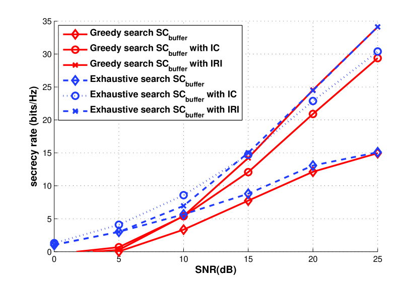
In Fig. 3, with IRI cancellation the secrecy rate is better than the one without IRI cancellation. Compared with a single-antenna scenario, the multi-user MIMO system contributes to the overall improvement in the secrecy rate.
VI Conclusion
In this work, we have employed an opportunistic relay and jammer scheme to enhance the physical-layer secrecy rate performance. The proposed secrecy rate relay selection policy contributes to the improvement of the secrecy rate performance. Simulation results indicate that the secrecy rate criterion relay selection policy achieves the best secrecy rate performance and the greedy search can approach a higher secrecy rate performance in a multiuser MIMO relay system than existing buffer-aided relay systems.
References
- [1] C. Shannon, “Communication theory of secrecy systems,” Bell System Technical Journal, The, vol. 28, no. 4, pp. 656–715, Oct 1949.
- [2] A. D. Wyner, “The wire-tap channel,” Bell System Technical Journal, vol. 54, no. 8, pp. 1355–1387, 1975. [Online]. Available: http://dx.doi.org/10.1002/j.1538-7305.1975.tb02040.x
- [3] I. Csiszar and J. Korner, “Broadcast channels with confidential messages,” Information Theory, IEEE Transactions on, vol. 24, no. 3, pp. 339–348, May 1978.
- [4] A. Mukherjee, S. Fakoorian, J. Huang, and A. Swindlehurst, “Principles of physical layer security in multiuser wireless networks: A survey,” Communications Surveys Tutorials, IEEE, vol. 16, no. 3, pp. 1550–1573, Third 2014.
- [5] P. Clarke and R. C. de Lamare, “Transmit diversity and relay selection algorithms for multirelay cooperative mimo systems,” IEEE Transactions on Vehicular Technology, vol. 61, no. 3, pp. 1084–1098, 2012.
- [6] N. Zlatanov and R. Schober, “Buffer-aided relaying with adaptive link selection-fixed and mixed rate transmission,” IEEE Transactions on Information Theory, vol. 59, no. 5, pp. 2816–2840, May 2013.
- [7] N. Nomikos, T. Charalambous, I. Krikidis, D. Skoutas, D. Vouyioukas, and M. Johansson, “Buffer-aided successive opportunistic relaying with inter-relay interference cancellation,” in Personal Indoor and Mobile Radio Communications (PIMRC), 2013 IEEE 24th International Symposium on, Sept 2013, pp. 1316–1320.
- [8] N. Nomikos, P. Makris, D. Vouyioukas, D. Skoutas, and C. Skianis, “Distributed joint relay-pair selection for buffer-aided successive opportunistic relaying,” in Computer Aided Modeling and Design of Communication Links and Networks (CAMAD), 2013 IEEE 18th International Workshop on, Sept 2013, pp. 185–189.
- [9] J. H. Lee and W. Choi, “Multiuser diversity for secrecy communications using opportunistic jammer selection: Secure dof and jammer scaling law,” IEEE Transactions on Signal Processing, vol. 62, no. 4, pp. 828–839, Feb 2014.
- [10] X. Lu and R. C. Lamare, “Opportunistic relay and jammer cooperation techniques for physical-layer security in buffer-aided relay networks,” in The Twelfth International Symposium on Wireless Communication Systems (ISWCS), 2015.
- [11] Y. Jing and H. Jafarkhani, “Single and multiple relay selection schemes and their achievable diversity orders,” IEEE Trans. Wireless Commun., vol. 8, no. 3, pp. 1084–1098, Mar 2009.
- [12] P. Clarke and R. C. de Lamare, “Transmit diversity and relay selection algorithms for multi-relay cooperative MIMO systems,” IEEE Trans. Veh. Technol, vol. 61, no. 3, pp. 1084–1098, Mar 2012.
- [13] M. Ding, S. Liu, H. Luo, and W. Chen, “MMSE based greedy antenna selection scheme for AF MIMO relay systems,” IEEE Signal Process. Lett, vol. 17, no. 5, pp. 433–436, May 2010.
- [14] S. Song and W. Chen, “MMSE based greedy eigenmode selection for AF MIMO relay channels,” IEEE Globecom, Anaheim, CA, Dec. 2012.
- [15] S. Talwar, Y. Jing, and S. Shahbazpanahi, “Joint relay selection and power allocation for two-way relay networks,” IEEE Signal Process. Lett, vol. 18, no. 2, pp. 91–94, Feb 2011.
- [16] J. Chen, R. Zhang, L. Song, Z. Han, and B. Jiao, “Joint relay and jammer selection for secure two-way relay networks,” Information Forensics and Security, IEEE Transactions on, vol. 7, no. 1, pp. 310–320, Feb 2012.
- [17] G. Chen, Z. Tian, Y. Gong, Z. Chen, and J. Chambers, “Max-ratio relay selection in secure buffer-aided cooperative wireless networks,” IEEE Transactions on Information Forensics and Security, vol. 9, no. 4, pp. 719–729, April 2014.
- [18] X. Lu, K. Zu, and R. C.de Lamare, “Lattice-reduction aided successive optimization tomlinson-harashima precoding strategies for physical-layer security in wireless networks,” in Sensor Signal Processing for Defence (SSPD), 2014, Sept 2014, pp. 1–5.
- [19] K. Zu and R. de Lamare, “Low-complexity lattice reduction-aided regularized block diagonalization for mu-mimo systems,” IEEE Communications Letters, vol. 16, no. 6, pp. 925–928, June 2012.
- [20] K. Zu, R. de Lamare, and M. Haardt, “Generalized design of low-complexity block diagonalization type precoding algorithms for multiuser mimo systems,” IEEE Trans. Communications, vol. 61, no. 10, pp. 4232–4242, October 2013.
- [21] Z. K, R. de Lamare, and M. Haardt, “Multi-branch tomlinson-harashima precoding design for mu-mimo systems: Theory and algorithms,” IEEE Trans. Communications, vol. 62, no. 3, pp. 939–951, March 2014.
- [22] Y. Cai, R. C. de Lamare, and R. Fa, “Switched interleaving techniques with limited feedback for interference mitigation in ds-cdma systems,” IEEE Transactions on Communications, vol. 59, no. 7, pp. 1946–1956, 2011.
- [23] R. C. de Lamare and R. C. de Lamare, “Adaptive reduced-rank mmse filtering with interpolated fir filters and adaptive interpolators,” IEEE Signal Processing Letters, vol. 12, no. 3, March 2005.
- [24] W. Chen, L. Dai, K. B. Letaief, and Z. Cao, “A unified cross-layer framework for resource allocation in cooperative networks,” IEEE Trans. Wireless Commun., vol. 7, no. 8, pp. 3000–3012, Aug. 2008.
- [25] R. Meng, R. C. de Lamare, and V. H. Nascimento, “Sparsity-aware affine projection adaptive algorithms for system identification,” in Proc. Sensor Signal Processing for Defence Conference, London, UK, 2011.
- [26] Z. Yang, R. de Lamare, and X. Li, “Sparsity-aware space-time adaptive processing algorithms with l1-norm regularisation for airborne radar,” Signal Processing, IET, vol. 6, no. 5, pp. 413–423, July 2012.
- [27] ——, “L1-regularized stap algorithms with a generalized sidelobe canceler architecture for airborne radar,” Signal Processing, IEEE Transactions on, vol. 60, no. 2, pp. 674–686, Feb 2012.
- [28] R. C. de Lamare and R. C. de Lamare, “Sparsity-aware adaptive algorithms based on alternating optimization and shrinkage,” IEEE Signal Processing Letters, vol. 21, no. 2, pp. 225–229, January 2014.
- [29] R. C. de Lamare and R. Sampaio-Neto, “Reduced–rank adaptive filtering based on joint iterative optimization of adaptive filters,” IEEE Signal Process. Lett., vol. 14, no. 12, pp. 980–983, December 2007.
- [30] ——, “Reduced-rank space–time adaptive interference suppression with joint iterative least squares algorithms for spread-spectrum systems,” IEEE Transactions Vehicular Technology, vol. 59, no. 3, pp. 1217–1228, March 2010.
- [31] ——, “Adaptive reduced-rank equalization algorithms based on alternating optimization design techniques for MIMO systems,” IEEE Transactions on Vehicular Technology, vol. 60, no. 6, pp. 2482–2494, July 2011.
- [32] ——, “Adaptive reduced-rank processing based on joint and iterative interpolation, decimation, and filtering,” IEEE Transactions on Signal Processing, vol. 57, no. 7, pp. 2503–2514, July 2009.
- [33] R. Fa, R. C. de Lamare, and L. Wang, “Reduced-rank stap schemes for airborne radar based on switched joint interpolation, decimation and filtering algorithm,” IEEE Transactions on Signal Processing, vol. 58, no. 8, pp. 4182–4194, August 2010.
- [34] S. Li, R. C. de Lamare, and R. Fa, “Reduced-rank linear interference suppression for ds-uwb systems based on switched approximations of adaptive basis functions,” IEEE Transactions on Vehicular Technology, vol. 60, no. 2, pp. 485–497, Feb 2011.
- [35] R. C. de Lamare, R. Sampaio-Neto, and M. Haardt, “Blind adaptive constrained constant-modulus reduced-rank interference suppression algorithms based on interpolation and switched decimation,” IEEE Transactions on Signal Processing, vol. 59, no. 2, pp. 681–695, Feb 2011.
- [36] M. L. Honig and J. S. Goldstein, “Adaptive reduced-rank interference suppression based on the multistage wiener filter,” IEEE Transactions on Communications, vol. 50, no. 6, June 2002.
- [37] R. C. de Lamare, M. Haardt, and R. Sampaio-Neto, “Blind adaptive constrained reduced-rank parameter estimation based on constant modulus design for cdma interference suppression,” IEEE Transactions on Signal Processing, vol. 56, no. 6, June 2008.
- [38] R. C. de Lamare and R. Sampaio-Neto, “Minimum mean-squared error iterative successive parallel arbitrated decision feedback detectors for ds-cdma systems,” IEEE Transactions on Communications, vol. 56, no. 5, pp. 778–789, 2008.
- [39] P. Li, R. C. De Lamare, and R. Fa, “Multiple feedback successive interference cancellation detection for multiuser mimo systems,” IEEE Transactions on Wireless Communications, vol. 10, no. 8, pp. 2434–2439, 2011.
- [40] R. de Lamare, “Adaptive and iterative multi-branch mmse decision feedback detection algorithms for multi-antenna systems,” IEEE Transactions on Wireless Communications, vol. 12, no. 10, pp. 5294–5308, 2013.
- [41] I. Krikidis, T. Charalambous, and J. Thompson, “Buffer-aided relay selection for cooperative diversity systems without delay constraints,” IEEE Transactions on Wireless Communications, vol. 11, no. 5, pp. 1957–1967, May 2012.