Unique magnetic structure of YbCo2Si2
Abstract
We report on the results of powder and single crystal neutron diffraction to investigate the magnetic order in YbCo2Si2 below the Néel temperature K in detail. Two different magnetically ordered phases can clearly be distinguished. At lowest temperatures a commensurate magnetic structure with a propagation vector is found, while the intermediate phase ( K) is characterized by an incommensurate magnetic structure with . The magnetic structure in YbCo2Si2 is in marked contrast to all other known RCo2Si2 compounds (R = rare earth element) likely due to some itineracy of the Yb 4f states being responsible for the magnetism.
pacs:
71.27.+a, 75.25.-j, 61.05.F-I Introduction
Yb-based compounds have attracted particular interest due to their unique physical properties such as intermediate-valence, heavy-fermion, and recently non-Fermi-liquid (NFL) phenomena in the vicinity of quantum critical points (QCPs) Temmerman et al. (1999); Custers et al. (2003); Gegenwart et al. (2008). One of the most intensively studied Yb-based heavy-fermion compounds is YbRh2Si2 which orders antiferromagnetically at a very low 0.07 K Trovarelli et al. (2000). The magnetic order can be suppressed to zero by application of a small critical magnetic field or by applying slightly negative chemical pressure through substitution of La, Ir, or Ge for Yb, Rh and Si, respectively Custers et al. (2003); Gegenwart et al. (2008); Trovarelli et al. (2000); Ferstl et al. (2005); Friedemann et al. (2009). Resistivity and thermodynamic measurements of this compound show interesting properties such as pronounced NFL behavior Trovarelli et al. (2000), divergence of the heavy quasiparticle mass and of the magnetic Grüneisen parameter at the QCP Custers et al. (2003); Tokiwa et al. (2009). However, the very weak antiferromagnetic order in YbRh2Si2 makes it difficult to study the unusual properties using microscopic probes. Several attempts to determine the magnetic structure by neutron diffraction failed due to the small size of the ordered magnetic moment (10-3 ) Ishida et al. (2003). A further complication in performing neutron scattering on YbRh2Si2 is the high neutron absorption cross section of Rh restricting the effective sample thickness. Nevertheless, dynamic magnetic correlations were detected at incommensurate positions , at low temperatures K exhibiting no dispersion Stock et al. (2012). These incommensurate spin correlations evolve into ferromagnetic correlations at a higher temperature of K Stock et al. (2012).
To overcome the difficulties in studying pure YbRh2Si2 we followed the route to stabilize the antiferromagnetic state by application of hydrostatic pressure or by suitable chemical substitution. The latter reduces the unit cell volume and acts as positive chemical pressure. This results in an increase of both, the ordering temperature and the size of the ordered moment. Our studies indeed show that substitution of Rh by isovalent Co stabilizes the antiferromagnetic state and enhances Klingner et al. (2011); Westerkamp et al. (2008). Recently, we reported neutron powder diffraction results on YbCo2Si2 Kaneko et al. (2010) where we observed for the first time magnetic superstructure peaks at lowest temperature which exhibit a pronounced shift in an intermediate phase below . The intensities of these two phases show significant changes and point to marked differences in the magnetic structures Kaneko et al. (2010). However, in those initial experiments we could not determine unambiguously the propagation vector, since only very few magnetic peaks could be observed. Therefore, a more detailed understanding of the magnetic ordering phenomena in YbCo2Si2 is highly desired. Furthermore, the magnetic structure in YbCo2Si2 serves as a reference for iso-structural quantum-critical YbRh2Si2.
The magnetic properties of YbCo2Si2 (space group ) were initially studied on polycrystalline samples by Hodges who observed antiferromagnetic order below TN 1.7 K with an ordered magnetic moment of /Yb using Mössbauer spectroscopy measurements Hodges (1987). He interpreted the reduced moment in comparison to e.g. the free Yb3+ moment as a result of crystalline electric field (CEF) effects. Later on, magnetization Kolenda and Szytuła (1989); Klingner et al. (2011b) and inelastic neutron powder measurements Goremychkin and Osborn (2000) confirmed the Yb valence to be trivalent and revealed a CEF level scheme of this tetragonal compound with a ground state doublet and excited doublets at , and meV. Recently, we studied single-crystalline YbCo2Si2 using magnetic susceptibility, magnetization, specific heat and electrical resistivity measurements Mufti et al. (2010); Pedrero et al. (2010); Klingner et al. (2011); Klingner et al. (2011b). As a result, YbCo2Si2 displays a pronounced easy-plane anisotropy and exhibits two magnetic transitions at K and K. The high-temperature susceptibility follows a Curie-Weiss behavior with an effective moment /Yb in close agreement with the free Yb3+ moment and a Weiss temperature and K for magnetic fields parallel and perpendicular to the basal plane, respectively. No magnetic contribution from Co has been observed Klingner et al. (2011); Kolenda and Szytuła (1989); Klingner et al. (2011b). Magnetization, susceptibility and magnetoresistance measurements indicate a complex phase diagram with some anisotropy in the basal plane Pedrero et al. (2010); Mufti et al. (2010). Here we report the results of our investigation from powder and single crystal diffraction measurements to study the magnetic structure of the two magnetically ordered phases in YbCo2Si2.
II Experiment
Single crystals and polycrystalline samples of YbCo2Si2 were prepared by flux growth using indium as flux Klingner et al. (2011). X-ray powder diffraction was used to verify the crystal structure. Neutron powder diffraction experiments were performed at the Berlin Neutron Scattering Center (BENSC) using the diffractometer E2 with a neutron wavelength Å. Approximately g of YbCo2Si2 powder was sealed inside a copper container. A small amount of a deuterated methanol-ethanol mixture in the sample container, which solidifies upon cooling, improved the thermal coupling, but also resulted in an increased background and a broad hump around deg. as seen for all pattern in Fig. 1. The sample can was mounted on a 3He stick and allowed measurements in the temperature range between and K. Typical counting times per powder pattern displayed in Fig. 1 were hours. The powder pattern were analyzed by the Rietveld method using FullProf Rodriguez-Carvajal (1993). Single-crystal neutron diffraction was carried out on the instrument SXD at the ISIS facility which utilizes the time-of-flight Laue technique Keen et al. (2006). A YbCo2Si2 single crystal of approximate dimensions mm3 ( mg) was mounted on copper foil and attached to the cold plate of a 3He cryostat. Data were collected at temperatures , and K. In addition, an elastic neutron scattering experiment was performed on the triple-axis spectrometer TAS-2, installed at the research reactor JRR-3 in Tokai, Japan. Neutrons with a wavelength Å ( meV) were used together with a horizontal collimation open-80’-80’-open and a pyrolithic graphite (PG) filter on the incident beam was used to eliminate higher-order contamination. The single crystal with a mass of mg was mounted on a copper post connected to the cold finger of a 3He cryostat with the axis vertical resulting in a horizontal scattering plane. Data were taken on TAS-2 at temperatures K with typical counting times of s per point. All neutron intensities are normalized to a monitor (”mon”) in the incident neutron beam.
III Results and discussion
The x-ray powder diffraction pattern of YbCo2Si2 obtained at room temperature as well as the neutron powder diffraction pattern taken at K confirm the tetragonal ThCr2Si2-type structure () in which the Yb atoms occupy the 2a site, while the Co atoms sit on the 4d site and Si atoms are placed on the 4e site with . The refined lattice parameters from x-ray diffraction at room temperature are Å and Å in good agreement with the previously reported values by Kolenda et al.Kolenda and Szytuła (1989).
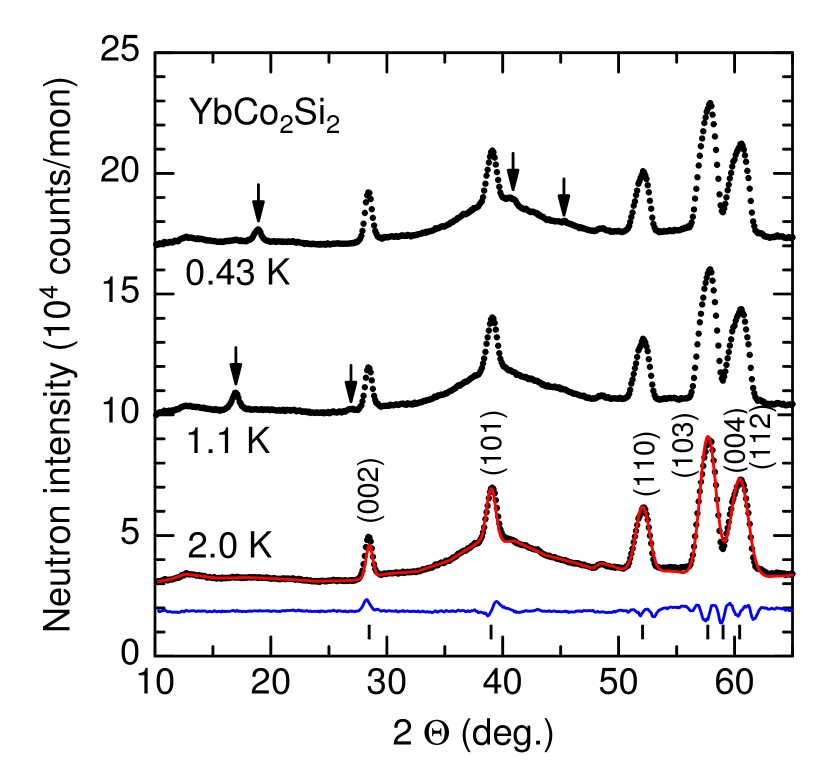
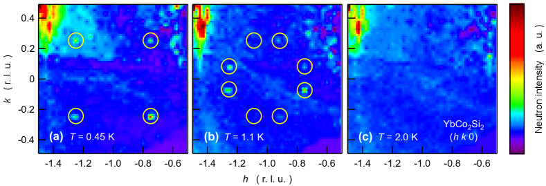
Fig. 1 displays the neutron powder pattern of YbCo2Si2 taken at three different temperatures corresponding to the paramagnetic regime at K and in the two magnetically ordered phases at and K. The measurements are in line with the previous neutron diffraction results Kaneko et al. (2010) and reveal additional Bragg peaks below K due to magnetic ordering. However, only three magnetic peaks at lowest temperature and two magnetic peaks in the intermediate phase are clearly visible making it difficult to unambiguously determine the propagation vector. For a reliable determination of the propagation vector single-crystal neutron diffraction is inevitable and was carried out on SXD. The neutron intensity in a part of the reciprocal scattering plane in YbCo2Si2 is shown as color-coded intensity maps in Fig. 2 for , and K. Magnetic superstructure peaks have been observed in the ground state at K and in the intermediate phase at K and are marked by yellow circles. They can be indexed as and in the ground state whereas the magnetic peaks in the intermediate phase are located at , , and (cf. Fig. 2 (a) and (b)). The intensities at and are very low, much weaker than at the other symmetry-equivalent positions, likely due to domain population.
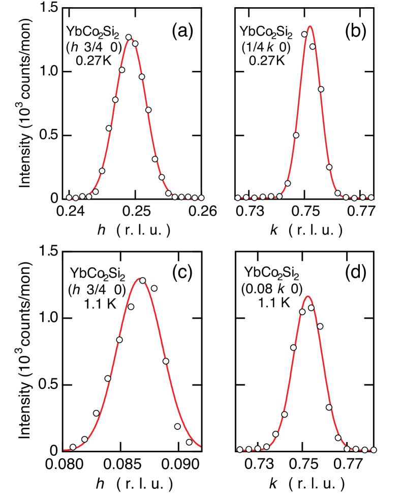
The neutron data taken on TAS-2 allowed a more accurate determination of the propagation vector. Fig. 3 shows scans along and across magnetic peaks in reciprocal space in the ground state and in the intermediate phase. At lowest temperature K one magnetic peak was observed at the commensurate position (cf. Fig.3(a) and (b)). Fig. 3 (c) and (d) reveal the position of a magnetic peak in the intermediate phase to be at . Taking the positions of several magnetic peaks together, these single-crystal measurements give clear evidence that the magnetic order at lowest temperatures is commensurate with a propagation vector while the intermediate phase is characterized by an incommensurate structure with . Equivalent to is the propagation vector when interchanging the - and -component of within the tetragonal structure. No change of the incommensurate value of within the measurement accuracy has been detected between and . The absence of and magnetic reflections indicates that the magnetic structure in both phases is not as simple as for other members of the family of RCo2Si2 compounds (R= Pr, Nd, Ho, Tb and Dy) whose magnetic order can be represented as an antiferromagnetic stacking of ferromagnetic -planes along the tetragonal -axis Leciejewicz et al. (1983). A reliable determination of magnetic intensities from the single-crystal measurements was not possible because absorption cannot be neglected for the very thin, plate-like crystals, and due to the effect of domain formation and population in this highly symmetrical, tetragonal compound.
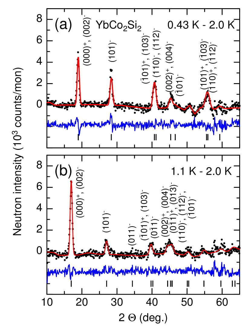
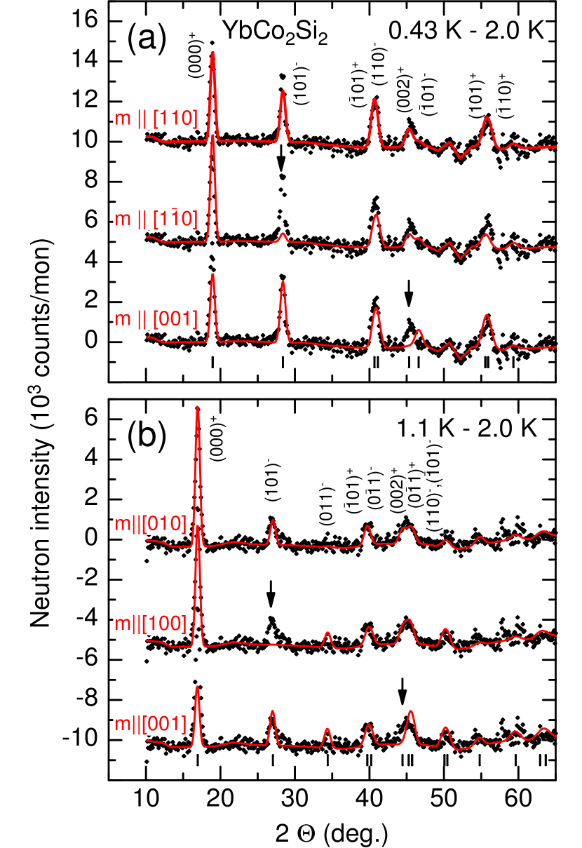
Instead, the neutron powder pattern of YbCo2Si2 were reinvestigated with the knowledge of the propagation vectors. In order to separate the magnetic contribution to the powder pattern, the data recorded in the paramagnetic regime at K were subtracted from the pattern at lower temperatures. The resulting difference pattern are displayed in Fig. 4 together with fits of the magnetic structure to the data (see below). The propagation vectors are validated by the powder measurements and the positions of the observed magnetic satellite peaks are well described by and . Moreover, the existence of magnetic satellite peaks of the and nuclear peaks in both phases indicates that a considerable fraction of the ordered moment is perpendicular to the c-axis. This is in good agreement with previous results from the Mössbauer spectroscopy Hodges (1987).
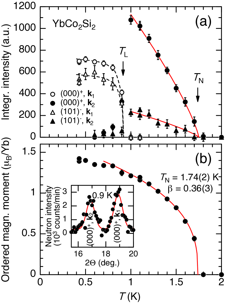
The two strongest magnetic superstructure peaks in the powder diffraction pattern of YbCo2Si2, the and satellite peaks [ denotes a satellite peak of the nuclear peak], have been recorded at several temperatures. Their integrated intensity as a function of temperature is plotted in Fig. 5(a). Magnetic intensity fully vanishes just above K in close agreement with bulk measurements Klingner et al. (2011). In contrast to the continuous phase transition at , the intensity of the commensurate magnetic peaks disappears suddenly at K. Moreover, as displayed in the inset of Fig. 5(b) the pattern recorded at K shows the magnetic superstructure peaks of both phases, the commensurate as well as the incommensurate one, i.e., phase separation takes place indicating a first-order transition from the commensurate low-temperature to the incommensurate intermediate-temperature phase. Our results are consistent with the first-order nature of this transition seen in heat capacity and magnetization measurements Klingner et al. (2011); Pedrero et al. (2011).
We now turn to the discussion of the magnetic structure in YbCo2Si2 in more detail. Magnetic neutron scattering only probes magnetic moment components perpendicular to the scattering vector. Hence, the strong increase of the magnetic intensity from the low-temperature to the intermediate-temperature phase is mainly due to a spin reorientation taking place at the commensurate – incommensurate transition. The change in the propagation vector from to seems only to be a minor effect.
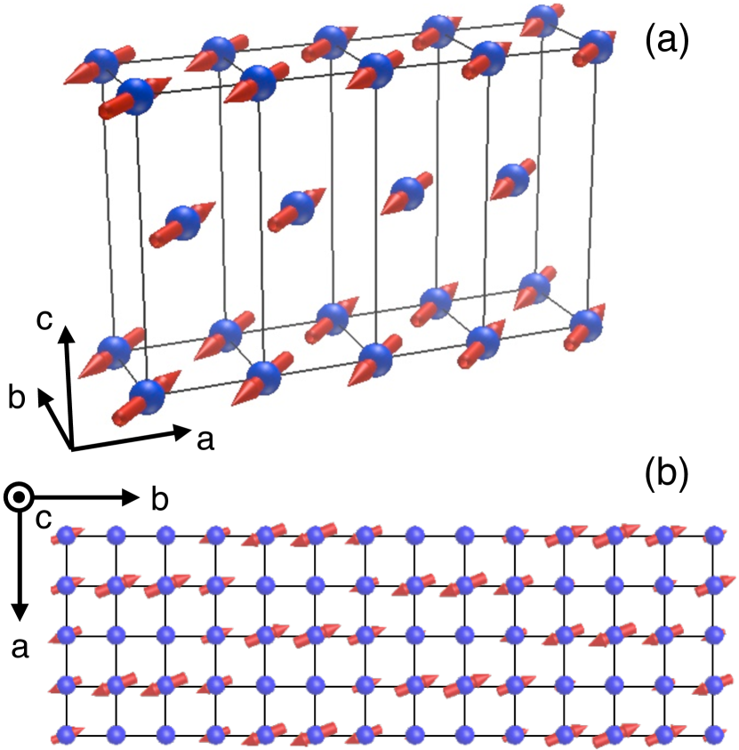
In order to determine the magnetic structure a magnetic symmetry analysis has been performed to find the allowed irreducible representations and their basis vectors for the propagation vectors and in the space groups (for details see Appendix). Such an analysis for the YbCo2Si2 magnetic structure (Yb3+ on 2a site of the tetragonal unit cell and a magnetic propagation vector ) yields as possible directions for the magnetic moments (the basis vectors of the irreducible representations) the , or the direction (cf. Table 1). Moments along can be excluded, since the magnetic satellite peak would then be almost vanished. However, this magnetic peak at deg. is clearly visible. Furthermore, magnetization measurements indicate that YbCo2Si2 is an easy-plane antiferromagnet Pedrero et al. (2011). To decide whether the magnetic moments are perpendicular or (anti-)parallel to the projection of the propagation vector on to the basal plane, we fitted the powder pattern for both possible moment directions. Assuming moments along we could only get the intensity of the primary peak correct while the intensities of all magnetic satellites at higher scattering angles are systematically strongly underestimated. In contrast, assuming magnetic moments in direction a satisfactory fit to all magnetic peaks can be obtained as seen in Fig. 4(a). With and moments along we obtain a commensurate antiferromagnetic structure with equal moments on each Yb site. The size of the ordered moment at K is determined to /Yb in close agreement with the Mössbauer results. Fig. 6(a) is a visualization of the magnetic structure where only the modulation of the magnetic moments along is shown. Along the direction the same modulation of the moments occurs as along .
Above K, i.e., in the incommensurate intermediate phase with , moments along can be ruled out for similar reasons as in the low-temperature phase. However, symmetry analysis allows also for magnetic moments in the tetragonal basal plane along and/or . Considering an amplitude-modulated magnetic structure and the moment direction along the calculation yields for the two most prominent magnetic satellites at lowest scattering angles (cf. Fig. 4(b)) a ratio of the intensities while the ratio of the measured intensities amounts to . Hence, such a model with magnetic moments only along can also be discarded. Assuming that the Yb moments are amplitude modulated and point in the direction results in a ratio being quite close to the observation. The fit of this model to the powder pattern is displayed in Fig. 4(b) and describes already well the data. It yields for the ordered magnetic moment /Yb (root mean square value) at K. It should be noted that no higher harmonic magnetic satellite peaks, i.e., G3k2, G5k2, … ( being a reciprocal lattice vector) have been observed. Allowing the magnetic moments to take any direction within the tetragonal basal plane as permitted by symmetry (see Appendix), either an amplitude-modulated magnetic structure or an in-plane spiral spin arrangement fit equally well the experimental data. Only with the help of polarized neutron diffraction can both structures be distinguished and the incommensurate magnetic structure unambiguously be determined. The fit of the amplitude-modulated structure gives a moment in the basal plane forming an angle of about deg. with the axis. The modulation of the magnetic Yb3+ moments within the basal plane of YbCo2Si2 is displayed in Fig. 6(b). As a result, the magnetic moments in the intermediate phase are aligned almost perpendicular to the propagation vector and hence to which is the origin of the strong increase in intensity of the peak when crossing the commensurate – incommensurate phase boundary. Since thermodynamic and transport properties display strong anisotropies within the basal plane with quite different magnetic phase diagrams Mufti et al. (2010); Pedrero et al. (2011), we favor the amplitude-modulated magnetic structure instead of a spiral magnetic structure for the intermediate, incommensurate phase. However, as already mentioned above polarized neutron diffraction is desired to fully solve the structure in the incommensurate phase. The intensities of the few magnetic peaks recorded in the single crystal measurement are consistent with the magnetic structure derived from the neutron powder measurements.
The temperature dependence of the ordered magnetic moment has been extracted from fits of the two above-mentioned magnetic structures to the whole powder pattern taken at different temperatures and is shown in Fig. 5(b). The ordered moment increases smoothly below without any major anomaly at corroborating that at just a spin reorientation takes place. A power-law fit of the form to the ordered magnetic moment (solid line in Fig. 5(b)) describes well the data from about K up to . It yields a Néel temperature K and a critical exponent , the latter being quite close to expected for a 3D Heisenberg system, but still compatible with within the 3D model Collins (1989). As expected, with the same and the temperature dependence of the and peaks (), whose integrated intensities were obtained independently by single peak fits, is reproduced as indicated by the solid lines in Fig. 5(a). It is shown above that the magnetic moments of the antiferromagnetic structure are confined to the basal plane as expected from the CEF analysis and the anisotropy in the magnetic susceptibility Klingner et al. (2011b). Hence a 3D model might be appropriate for YbCo2Si2. However, the almost isotropic critical magnetic fields to suppress antiferromagnetic order Pedrero et al. (2010); Mufti et al. (2010) suggest a Heisenberg scenario. Further measurements are needed to decide which model is better suited to describe YbCo2Si2.
Comparing the magnetic structure of YbCo2Si2 with other members of the RCo2Si2 (R = rare earth Pr, Nd, Tb, Dy, Ho, Er and Tm) series similarities, but also marked differences become apparent. Well below their individual ordering temperatures all rare-earth based RCo2Si2 except YbCo2Si2 order antiferromagnetically with a propagation vector in a collinear magnetic structure. Ferromagnetically ordered basal planes are stacked antiferromagnetically along the -direction and break the body centering of the tetragonal crystal structure Leciejewicz et al. (1983); Leciejewicz and Szytuła (1983). While the magnetic moments in the light and the heavy rare-earth based RCo2Si2 up to HoCo2Si2 are aligned along , from ErCo2Si2 on and including YbCo2Si2 the moments are oriented perpendicular to the -axis. This can be understood as a result of the different CEF schemes as determined by inelastic neutron scattering and Mössbauer spectroscopy Görlich et al. (1982); Leciejewicz et al. (1983); Leciejewicz and Szytuła (1983); Goremychkin and Osborn (2000); Harker et al. (2002). The origin lies in the sign of the parameter (in Stevens notation) in the CEF Hamiltonian, which is related to the paramagnetic Curie-Weiss temperatures along the different crystallographic directions. Depending on the sign of the parameter a change from a large uniaxial magnetic anisotropy (magnetic moments along the -direction) to a basal-plane anisotropy (moments perpendicular to the -axis) occurs. Common to all RCo2Si2 is the existence of an incommensurate modulated magnetic phase just below the Néel temperature Shigeoka et al. (1988, 1989); Szytula et al. (2000); Schobinger-Papamantellos et al. (2003) whose origin lies in the RKKY-interaction, the oscillatory exchange interaction between the rare-earth 4f electrons mediated by the conduction electrons.
The interplay between the RKKY-interaction, favoring incommensurate modulated magnetic structures, and the CEF effects, preferring certain moment directions, determines the experimentally realized magnetic structures in the RCo2Si2 compounds. In contrast to all other RCo2Si2, YbCo2Si2 exhibits unusual magnetic propagation vectors. In YbCo2Si2 not only an antiferromagnetic stacking of the Yb3+ moments occurs along , but also the ordering in the basal plane is antiferromagnetic. Moreover, both propagation vectors, and , together with moments in the basal plane break the tetragonal symmetry of YbCo2Si2. It remains currently an open question to which extent the symmetry of the crystallographic structure is also reduced in the magnetically ordered regime. The occurrence of two quite different magnetically ordered phases in YbCo2Si2 indicates that both magnetic structures are energetically close to each other. This suggests that the magnetic interactions in YbCo2Si2 might be frustrated. Especially for the quantum-critical sister compound YbRh2Si2 the possible existence of frustration is an important issue and will be further pursued in the future.
While the magnetic order in the other RCo2Si2 is of purely localized moments, the unusual magnetic behavior of YbCo2Si2 might well be a result of the fact that the 4f electrons of Yb are not fully localized, but retain some small itinerant character. A small amount of itinerant Yb 4f states has indeed been recently seen in ARPES measurements on YbCo2Si2 Güttler et al. (2014) and is also corroborated by heat capacity and resistivity measurements Klingner et al. (2011). Interestingly, a similar effect is observed in the isovalent Kondo lattice CeRh2Si2. This compound presents a complex antiferromagnetic order of seemingly completely localized Ce3+ moments Grier et al. (1984); Kawarazaki et al. (2000), but with propagation vectors in marked difference to those of the RRh2Si2 (R = rare earth) homologues with a stable rare earth local moment. In CeRh2Si2 the width of the quasi-elastic line in neutron scattering in the paramagnetic state indicates a significant Kondo interaction Severing et al. (1989). However, de Haas–van Alphen experiments did not reveal a strong effect of this Kondo interaction in the electronic states at the Fermi level Araki et al. (2001). Thus, in the two compounds YbCo2Si2 and CeRh2Si2, where the RKKY interaction succeeds over the Kondo effect, the latter does not lead to strong changes in the electronic states observed directly, but seems to strongly affect the propagation vector of the magnetically ordered state. Therefore, the propagation vector might be a very sensitive probe of hybridization effects in Kondo lattices with dominating RKKY interaction.
IV Conclusion
We have presented results of single crystal and powder neutron diffraction on YbCo2Si2 to study the magnetic order below K in detail. The magnetic structure in the ground state is a collinear structure with a propagation vector and ordered magnetic moments of /Yb oriented along . In the intermediate phase above K the magnetic order becomes incommensurate with and either a spiral spin arrangement in the basal plane or amplitude-modulated moments in the basal plane almost along . Magnetic intensity vanishes continuously at the Néel temperature K in accordance to thermodynamic and transport measurements and exhibits a critical exponent compatible with a 3D or Heisenberg system. The exceptional propagation vectors in YbCo2Si2 within the RCo2Si2 series might be related to the partial itinerant character of the Yb 4f states.
We greatly acknowledge fruitful discussions with M. Baenitz, M. Brando, A. Hannaske, S. Kirchner, and L. Pedrero. We thank C. Klausnitzer and R. Weise for technical support. Access to the ISIS spallation neutron source and the Berlin BER-II and Tokai JRR-3 reactor neutron sources is gratefully acknowledged. This work was financially supported by the DFG Research Unit 960 “Quantum Phase Transitions” and a Grant-in-Aid for Scientific Research (C) (No. 2454036) from the Japan Society of the Promotion of Science.
Appendix
| Propagation | Irreducible | Basis | |
|---|---|---|---|
| Vector k | Representation | Vector | |
For the determination of the magnetic structure we performed a representation analysis for both ground state and intermediate phase using the program BasIreps being part of the FullProf suite Rodriguez-Carvajal (1993). As a consequence of the Landau theory for a second-order phase transition such an analysis implies that only one irreducible representation becomes critical. Then, for the magnetic structure determination only the moment directions given by the basis vectors which belong to the irreducible representation being considered, have to be taken into account. Since the transition at the Néel temperature is second order, representation analysis certainly is valid for the intermediate phase (). However, even for the commensurate magnetic structure at lowest temperatures representation analysis holds since this state can also be reached from the paramagnetic state at high fields at low via a second-order transition as a function of (decreasing) magnetic field along Pedrero et al. (2011).
The representation analysis for the magnetic Yb on the 2a site within the tetragonal structure of YbCo2Si2 and a propagation vector yields for the magnetic representation three one-dimensional irreducible representations following Kovalev’s notation Kovalev (1993). The basis vectors of these irreducible representations indicate possible directions of the ordered magnetic moment. Table 1 displays the irreducible representations as well as the basis vectors.
For the intermediate phase () the magnetic representation decomposes into two one-dimensional representations, one of which occurs twice, . The corresponding basis vectors together with their irreducible representations are again shown in Table 1. In addition to an amplitude-modulated structure equally possible is also a spiral structure in the intermediate phase since for the representation moments along and/or are allowed (see main text).
The different allowed magnetic structures have been fitted to the data, i.e., magnetic moments along , or as given by , or for the commensurate magnetic structure and moments along or in the basal plane ( and/or ) for the incommensurate intermediate phase ( or 2 representations). Fits are displayed in Fig. 7 together with the magnetic diffraction pattern already shown in Fig. 4. Clearly the commensurate structure is described by magnetic moments along ( representation), i.e. parallel to the basal-plane components of the propagation vector, while the intermediate phase is characterized by moments in the basal plane ( representation) with moments (almost) along , i.e. (almost) perpendicular to the propagation vector.
References
- Temmerman et al. (1999) W. M. Temmerman, Z. Szotek, A. Svane, P. Strange, H. Winter, A. Delin, B. Johansson, O. Eriksson, L. Fast, and J. M. Wills, Phys. Rev. Lett. 83, 3900 (1999).
- Custers et al. (2003) J. Custers, P. Gegenwart, K. Neumaier, H. Wilhelm, N. Oeschler, K. Ishida, Y. Kitaoka, C. Geibel, and F. Steglich, J. Phys.: Condens. Matter 15, S2047 (2003).
- Gegenwart et al. (2008) P. Gegenwart, Q. Si, and F. Steglich, Nat. Phys. 4, 186 (2008).
- Trovarelli et al. (2000) O. Trovarelli, C. Geibel, S. Mederle, C. Langhammer, F. M. Grosche, P. Gegenwart, M. Lang, G. Sparn, and F. Steglich, Phys. Rev. Lett. 85, 626 (2000).
- Ferstl et al. (2005) J. Ferstl, C. Geibel, F. Weickert, P. Gegenwart, T. Radu, T. Lühmann, and F. Steglich, Physica B 359-361, 26 (2005).
- Friedemann et al. (2009) S. Friedemann, T. Westerkamp, M. Brando, N. Oeschler, S. Wirth, P. Gegenwart, C. Krellner, C. Geibel, and F. Steglich, Nat. Phys. 5, 465 (2009).
- Tokiwa et al. (2009) Y. Tokiwa, P. Gegenwart, C. Geibel, and F. Steglich, J. Phys. Soc. Jpn. 78, 123708 (2009).
- Ishida et al. (2003) K. Ishida, D. E. MacLaughlin, B.-L. Young, K. Okamoto, Y. Kawasaki, Y. Kitaoka, G. J. Nieuwenhuys, R. H. Heffner, O. O. Bernal, W. Higemoto, et al., Phys. Rev. B 68, 184401 (2003).
- Stock et al. (2012) C. Stock, C. Broholm, F. Demmel, J. Van Duijn, J. W. Taylor, H. J. Kang, R. Hu, and C. Petrovic, Phys. Rev. Lett. 109, 127201 (2012).
- Klingner et al. (2011) C. Klingner, C. Krellner, M. Brando, C. Geibel, F. Steglich, D. V. Vyalikh, K. Kummer, S. Danzenbächer, S. L. Molodtsov, C. Laubschat, et al., Phys. Rev. B 83, 144405 (2011).
- Westerkamp et al. (2008) T. Westerkamp, P. Gegenwart, C. Krellner, C. Geibel, and F. Steglich, Physica B 403, 1236 (2008).
- Kaneko et al. (2010) K. Kaneko, O. Stockert, N. Mufti, K. Kiefer, C. Klingner, C. Krellner, C. Geibel, and F. Steglich, J. Phys.: Conf. Series 200, 032031 (2010).
- Hodges (1987) J. A. Hodges, EPL (Europhys. Lett.) 4, 749 (1987).
- Kolenda and Szytuła (1989) M. Kolenda and A. Szytuła, J. Magn. Magn. Mater. 79, 57 (1989).
- Klingner et al. (2011b) C. Klingner, C. Krellner, M. Brando, C. Geibel, and F. Steglich, New Journal of Physics 13, 083024 (2011b).
- Goremychkin and Osborn (2000) E. A. Goremychkin and R. Osborn, J. Appl. Phys. 87, 6818 (2000).
- Mufti et al. (2010) N. Mufti, C. Klingner, L. Pedrero, M. Brando, K. Kaneko, C. Krellner, O. Stockert, and C. Geibel, phys. stat. sol. (b) 247, 743 (2010).
- Pedrero et al. (2010) L. Pedrero, M. Brando, C. Klingner, C. Krellner, C. Geibel, and F. Steglich, J. Phys.: Conf. Series 200, 012157 (2010).
- Rodriguez-Carvajal (1993) J. Rodriguez-Carvajal, Physica B 192, 55 (1993).
- Keen et al. (2006) D. A. Keen, M. J. Gutmann, and C. C. Wilson, J. Appl. Cryst. 39, 714 (2006).
- Leciejewicz et al. (1983) J. Leciejewicz, M. Kolenda, and A. Szytula, Sol. State Comm. 45, 145 (1983).
- Pedrero et al. (2011) L. Pedrero, C. Klingner, C. Krellner, M. Brando, C. Geibel, and F. Steglich, Phys. Rev. B 84, 224401 (2011).
- Collins (1989) M. F. Collins, Magnetic Critical Scattering (Oxford University Press, New York, 1989).
- Leciejewicz and Szytuła (1983) J. Leciejewicz and A. Szytuła, Sol. State Comm. 48, 55 (1983).
- Görlich et al. (1982) E. A. Görlich, A. Z. Hrynkiewicz, R. Kmieć, and K. Tomala, J. Phys. C: Solid State Phys. 15, 6049 (1982).
- Harker et al. (2002) S. J. Harker, B. D. van Dijk, A. M. Mulders, P. C. M. Gubbens, G. A. Stewart, C. F. de Vroege, and K. H. J. Buschow, J. Phys.: Condens. Matter 14, 2705 (2002).
- Shigeoka et al. (1988) T. Shigeoka, N. Iwata, Y. Hashimoto, Y. Andoh, and H. Fujii, J. Phys. Colloques 49, C8-431 (1988).
- Shigeoka et al. (1989) T. Shigeoka, N. Iwata, Y. Hashimoto, Y. Andoh, and H. Fujii, Physica B 156–157, 741 (1989).
- Szytula et al. (2000) A. Szytula, M. Balanda, B. Penc, and M. Hofmann, J. Phys.: Condens. Matter 12, 7455 (2000).
- Schobinger-Papamantellos et al. (2003) P. Schobinger-Papamantellos, K. H. J. Buschow, C. Ritter, and L. Keller, J. Magn. Magn. Mater. 264, 130 (2003).
- Güttler et al. (2014) M. Güttler, K. Kummer, S. Patil, M. Höppner, A. Hannaske, S. Danzenbächer, M. Shi, M. Radovic, E. Rienks, C. Laubschat, C. Geibel, and D. V. Vyalikh, Phys. Rev. B 90, 195138 (2014).
- Grier et al. (1984) B. H. Grier, J. M. Lawrence, V. Murgai, and R. D. Parks, Phys. Rev. B 29, 2664 (1984).
- Kawarazaki et al. (2000) S. Kawarazaki, M. Sato, Y. Miyako, N. Chigusa, K. Watanabe, N. Metoki, Y. Koike, and M. Nishi, Phys. Rev. B 61, 4167 (2000).
- Severing et al. (1989) A. Severing, E. Holland-Moritz, and B. Frick, Phys. Rev. B 39, 4164 (1989).
- Araki et al. (2001) S. Araki, R. Settai, T. C. Kobayashi, H. Harima, and Y. Ōnuki, Phys. Rev. B 64, 224417 (2001).
- Kovalev (1993) O. V. Kovalev, Representations of the Crystallographic Space Groups (Gordon and Breach Science Publishers, 1993), 2nd ed.