Twisted spin vortices in a spinor-dipolar Bose-Einstein condensate with Rashba spin-orbit coupling
Abstract
We consider a spin-1 Bose-Einstein condensate with Rashba spin-orbit coupling and dipole-dipole interaction confined in a cigar-shaped trap. Due to the combined effects of spin-orbit coupling, dipole-dipole interaction, and trap geometry, the system exhibits a rich variety of ground-state spin structures, including twisted spin vortices. The ground-state phase diagram is determined with respect to the strengths of the spin-orbit coupling and dipole-dipole interaction.
pacs:
03.75.Mn, 03.75.Lm, 67.85.Bc, 67.85.FgI Introduction
Spin-orbit coupling is of fundamental importance in many branches of physics, such as quantum spin-Hall effect, topological insulators, and superconductivity D. C. Tsui ; I. Zutic ; M. Z. Hasan ; X. L. Qi . Recently, the NIST group has realized the light-induced vector potentials and the synthetic electric and magnetic fields in Bose-Einstein condensates (BECs) of neutral atoms using Raman processes Lin01 ; Y.-J. Lin1 ; Lin11 ; J. Dalibard . Remarkably, they also created a two-component spin-orbit coupled condensate of Rb atoms Lin02 . Artificial spin-orbit coupling (SOC) offers us a tremendous opportunity to study exotic quantum phenomena in many-body systems, which exhibit various symmetry-broken and topological condensate phases in pseudospin- systems C. J. Wu ; H. Zhai0 ; C. Wang ; T.-L. Ho ; X.-Q. Xu ; S. Sinha ; H. Hu ; B. Ramachandhran ; T. Kawakami . For spin- and - condensates, more exotic patterns form due to the competition between the SOC and spin-dependent interactions Z. F. Xu ; T. Kawakami1 ; S.-W. Su ; C.-F. Liu ; Z. Chen .
On the other hand, recent experimental realization of BECs of atomic species with large magnetic moments boosts interest in the field of quantum gases with dipole-dipole interaction (DDI) Gries ; T. Lahaye ; M. Lu ; K. Aikawa . Previous studies on spinor-dipolar BECs have shown that the interplay between spin-dependent interaction and DDI leads to rich topological defects and spin structures Kawaguchi1 ; Yi ; Kawaguchi2 ; Kawaguchi3 ; Gaw07 ; Helical ; Eto . Consequently, it is of particular interest to explore the effects of long-rang and anisotropic DDI on such a spin-orbit coupled system, which has recently drawn considerable attentions. More specifically, Deng et al. Y. Deng proposed an experimental scheme to create SOC in spin-3 Cr atoms using Raman processes. Wilson et al. have investigated the effects of DDI on a pseudospin- spin-orbit coupled condensate, and predicted the emergence of a thermodynamically stable ground state having a spin configuration called meron Meron . Furthermore, a number of quantum crystalline and quasicrystalline ground states were found in two-dimensional (2D) dipolar bosons with Rashba SOC Quantum Quasicrystals .
In this work, we consider a BEC of spin- bosons confined in a cigar-shaped trap potential, subject to both 2D SOC and DDI. The 2D SOC tends to create spin textures in the - plane, while the DDI can generate -dependent spin textures in an elongated system. As a result, 3D spin structures emerge in this system. We elucidate the ground-state spin textures as functions of the strengths of the SOC and DDI by numerically minimizing the energy functional. We will show a rich variety of ground-state spin textures, such as twisted spin vortices, in which spin vortices twist around each other along the direction.
The paper is organized as follows. In Sec. II, we formulate the theoretical model and briefly introduce the numerical method. In Sec. III, the ground-state phase diagram of the system is determined, and a detailed description of each phase is given. In Sec. IV, the main results of the paper are summarized.
II Formulation of the problem
We consider a BEC of spin- atoms with mass confined in a harmonic potential, which are subject to the 2D SOC. We employ the mean-field approximation and the state of the system is described by the spinor order parameter The single-particle energy is given by
| (1) |
where parametrizes the SOC strength, , and are the spin- matrices. The trap potential is axisymmetric, , where is the radial trap frequency and is the aspect ratio between the axial and radial trap frequencies. The -wave contact interaction energy is written as
| (2) |
where and with being the -wave scattering length for the scattering channel with total spin . The total atomic density satisfies , where is the total number of atoms. The spin density has the form
| (3) |
The DDI energy is given by
| (4) |
where , is the magnetic permeability of the vacuum, is the magnetic dipole moment of the atom, and . The total energy of the system is thus given by .
The ground state is numerically obtained by minimizing the total energy using the imaginary-time propagation method. For the imaginary-time evolution, the pseudospectral method with the fourth-order Runge-Kutta scheme is used. In the following numerical simulations, we work in dimensionless unit. The energy and length are normalized by and . In this unit, the wave function, the SOC coefficient , and the interaction coefficients , , and are normalized by , , and , respectively.
III Ground-state spin structures
The richness of the present system lies in the large number of free parameters, including the strength and sign of the contact interactions, DDI, SOC, aspect ratio, and so on. To highlight the effects of the SOC and DDI, we fix , , and , implicitly assuming that the ground-state spin texture is dominated by the SOC and DDI.
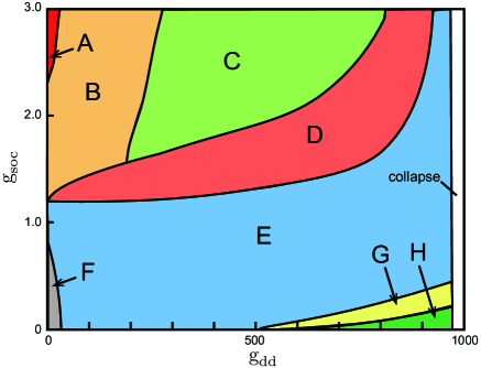
Our main results are summarized in Fig. 1, which shows the ground-state phase diagram of a spin-orbit coupled dipolar condensate with respect to and . There are eight different phases marked by A-H, which differ in density profiles, spin texture and angular momentum. In the following discussion, we will give a detailed description of each phase. In the white region of Fig. 1, the condensate collapses due to the attractive part of the DDI Lahaye , where no stable mean-field solution exists Koch . The critical value of for the collapse seems almost independent of .
We start from the case where both the SOC and DDI are sufficiently weak, indicated by the gray region F in Fig. 1. In this phase, the central region of the potential is occupied by component and the system is condensed to such component, leading to vanishing magnetization of the system. We note that this phase disappears with increasing either the SOC or DDI.
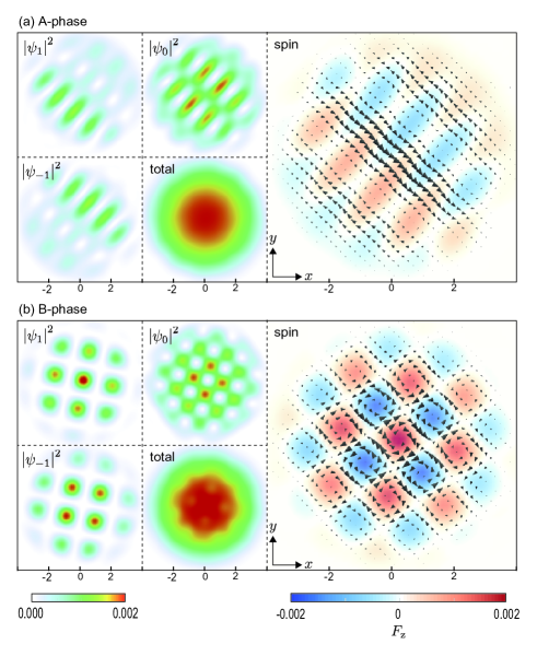
In the limit of strong SOC but weak DDI, the system exhibits a spin-stripe pattern, indicated by A-phase in Fig. 1. Typical density and spin distributions of such phase are shown in Fig. 2(a). In this phase, the spin texture on the - plane shows typical spin stripe structure, which is almost unchanged along the -axis. Actually, previous studies on trapped spin-orbit coupled BECs have shown that the spin stripe structure is known as one of the ground states at strong SOC in harmonic potential S. Sinha . In the present system, this state also exists for a strong SOC, but with a weak DDI.
With an increase in the strength of the DDI, B-phase emerges as the ground state, as shown in Fig. 1. Typical density and spin distributions of such phase are shown in Fig. 2(b). This phase is characterized by the checkerboard lattice of spin vortices on the - plane, in which spin vortices with and are alternately aligned. Such a pattern may be understood by the long-range nature of the DDI, which leads to a regular density distribution of each component. Similar to A-phase, the spin texture is almost independent of .
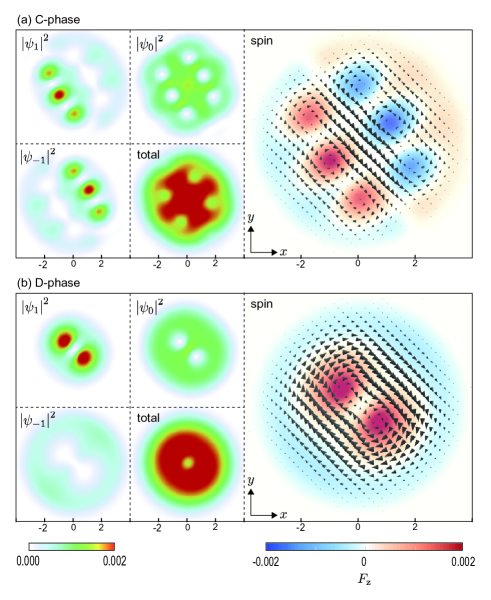
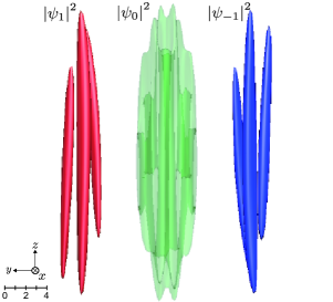
Increasing the DDI further, the spin vortex structures begin to have a dependence, and C-phase emerges as the ground-state of the system, as the yellow-green region in Fig. 1. Typical density and spin distributions of such phase are shown in Fig. 3(a). This phase has a spin-vortex train structure on the - plane, where components and are surrounded by component . The numbers of spin vortices with and are equal to each other, which increase with SOC. Three-dimensional (3D) isodensity surfaces of the state are shown in Fig. 4, which indicates that the spin vortex structure depends on due to the DDI.

With a further increase in the DDI, C-phase transforms to D-phase, as shown in Fig. 1. Its density and spin distributions and 3D structures are shown in Figs. 3(b) and 5, respectively. Interestingly, the spin structure significantly depends on and form a helical structure, leading to twisted spin vortices. We note that this spin structure, as well as C-phase, reflects the features of the SOC and DDI: multiple spin vortices are created by the SOC and they are twisted along the -axis by the DDI. In the region D of Fig. 1, we also observe three twisted spin vortices for a larger SOC. Our numerical results show that the degree of torsion increases with DDI, while the separation between the spin-vortices decreases. In the limit of strong DDI, the separation almost disappears and E-phase emerges as the ground state, as shown in blue region in Fig. 1.
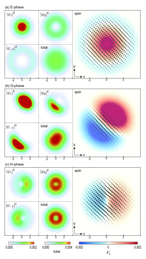
E-phase is characterized by its axisymmetric density distribution of each component, where the central region is occupied by component and outer regions by components and , as shown in Fig. 6(a). Components and have vorticities and , respectively. The spin texture in the - plane has a single spin vortex at the center, which is similar to the chiral spin-vortex state Yi ; Kawaguchi2 . This phase exists for strong DDI or weak SOC, and occupies the largest phase in the ground-state phase diagram in Fig. 1.
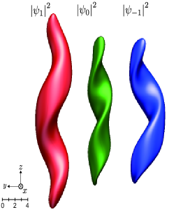
Finally, we move to another limit of weak SOC and strong DDI. In this region, there are two phases marked G and H in Fig. 1. The G-phase is shown in Figs. 6(b) and 7. This phase has a helical structure along the -axis, in which component are twined by the other two components, resulting in a double helix of and . The state shown in Figs. 6(b) and 7 has not only the spin angular momentum but also the orbital angular momentum in the direction. For a small , and components are balanced and the spin and orbital angular momenta disappear. In the present case of , this state is not the ground state for , while it can be a stationary state. It is found in Ref. Helical that this state can be the ground state for even without SOC.
The density and spin distributions of H-phase are shown in Fig. 6(c). The spin texture of this state is similar to that of the polar-core vortex, i.e., on the -axis and the transverse spin vectors rotate around the core. However, this state is different from the polar-core vortex, in that the axisymmetry is broken in and .
In all the phases demonstrated above, space- and time-reversed states of the ground states are also the ground states because of the symmetry of the Hamiltonian, that is, if is a ground state, is also a ground state. The rotation about the -axis also does not change the energy. A-, C-, F-, and H-phases have the space-time reversal symmetry and E-phase has the rotation symmetry about the -axis.
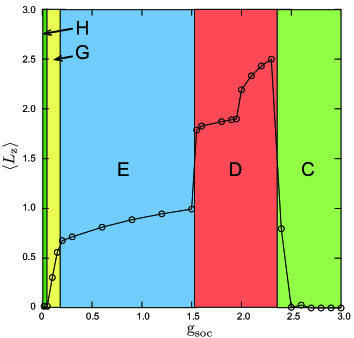
The -component of the orbital angular momentum, is notable in considering our system. Figure 8 shows as a function of for being fixed. The C- and H-phases scarcely have angular momentum, since there is the space-time reversal symmetry and is canceled between and . The first rapid increase in occurs in the G-phase (). The E-phase also has nonzero , since and have singly and doubly quantized vortices, respectively. In the D-phase, changes at , since the number of spin vortices changes from two to three. The maximum of is attained in the D-phase, and at , dramatically decreases and the ground state transforms to the C-phase with an increase in SOC.
We have also examined the cases of , and found that the B-E phases remained almost unchanged for ; the phase boundaries are slightly shifted. Our main results are thus unchanged for finite .
IV Conclusions
We have investigated the ground-state structures of a spin- Bose-Einstein condensate with the 2D Rashba SOC and DDI, confined in a cigar-shaped trap potential. Due to the interplay between the 2D-like pattern formation by the Rashba SOC and the dependence arising from the long-range DDI, we found a rich variety of ground-state phases, including the twisted spin vortices. We systematically explored the parameter space and obtained the ground-state phase diagram as a function of the strength of the SOC and DDI, which consists of eight different phases. For strong SOC and weak DDI, the stripe or plane-wave phase is obtained. Increasing the DDI, the spin-vortex lattice emerges (B-phase), which form square pattern due to the long-range nature of the DDI. In the opposite limit, i.e., for strong DDI and weak SOC, we have two symmetry broken states (G- and H-phases). The chiral spin-vortex state (E-phase) is the ground state for a wide parameter region. Between B- and E-phases, we found novel spin structures having both SOC and DDI features, which we call C-and D-phases. In the C-phase, bunches of spin vortices with opposite directions are twisted along the -axis, and in the D-phase, a few spin vortices form helical structures.
Both SOC and DDI couple the internal and external degrees of freedom in a BEC. Combining such effects, a wide variety of spin textures will be realized.
Acknowledgements.
This work was supported by JSPS KAKENHI Grant Numbers JP16K05505, JP26400414, and JP25103007, by the key project fund of the CAS for the “Western Light” Talent Cultivation Plan under Grant No. 2012ZD02, and by the Youth Innovation Promotion Association of CAS under Grant No. 2015334.References
- (1) D. C. Tsui, H. L. Stormer, and A. C. Gossard, Phys. Rev. Lett. 48, 1559 (1982).
- (2) I. Zutic, J. Fabian, and S. Das Sarma, Rev. Mod. Phys. 76, 323 (2004).
- (3) M. Z. Hasan and C. L. Kane, Rev. Mod. Phys. 82, 3045 (2010).
- (4) X. L. Qi and S. C. Zhang, Rev. Mod. Phys. 83, 1057 (2011).
- (5) Y.-J. Lin, R. L. Compton, A. R. Perry, W. D. Phillips, J. V. Porto, and I. B. Spielman, Phys. Rev. Lett. 102, 130401 (2009).
- (6) Y.-J. Lin, R. L. Compton, K. Jiménez-García, J. V. Porto, and I. B. Spielman, Nature (London) 462, 628 (2009).
- (7) Y.-J. Lin, R. L. Compton, K. Jiménez-García, W. D. Phillips, J. V. Porto, and I. B. Spielman, Nat. Phys. 7, 531 (2011).
- (8) J. Dalibard, F. Gerbier, Juzeliūnas, and P. Öhberg, Rev. Mod. Phys. 83, 1523 (2011).
- (9) Y.-J. Lin, K. Jiménez-García, and I. B. Spielman, Nature (London) 471, 83 (2011).
- (10) C. J. Wu, I. Mondragon-Shem, and X. F. Zhou, Chin. Phys. Lett. 28, 097102 (2011).
- (11) H. Zhai, Int. J. Mod. Phys. B 26, 1230001 (2012); H. Zhai, Rep. Prog. Phys. 78, 026001 (2015).
- (12) C. Wang, C. Gao, C.-M. Jian, and H. Zhai, Phys. Rev. Lett. 105, 160403 (2010)
- (13) T.-L. Ho and S. Zhang, Phys. Rev. Lett. 107, 150403 (2011).
- (14) X.-Q. Xu and J. H. Han, Phys. Rev. Lett. 107, 200401 (2011).
- (15) S. Sinha, R. Nath, and L. Santos, Phys. Rev. Lett. 107, 270401 (2011).
- (16) H. Hu, B. Ramachandhran, H. Pu, and X.-J. Liu, Phys. Rev. Lett. 108, 010402 (2012).
- (17) B. Ramachandhran, B. Opanchuk, X.-J. Liu, H. Pu, P. D. Drummond, and H. Hu, Phys. Rev. A 85, 023606 (2012).
- (18) T. Kawakami, T. Mizushima, M. Nitta, and K. Machida, Phys. Rev. Lett. 109, 015301 (2012).
- (19) Z. F. Xu, R. Lu, and L. You, Phys. Rev. A 83, 053602 (2011); Z. F. Xu, Y. Kawaguchi, L. You, and M. Ueda, Phys. Rev. A 86, 033628 (2012).
- (20) T. Kawakami, T. Mizushima, and K. Machida, Phys. Rev. A 84, 011607 (2011).
- (21) S.-W. Su, I.-K. Liu, Y.-C. Tsai, W. M. Liu, and S.-C. Gou, Phys. Rev. A 86, 023601 (2012).
- (22) C.-F. Liu and W. M. Liu, Phys. Rev. A 86, 033602 (2012).
- (23) Z. Chen and H. Zhai, Phys. Rev. A 86, 041604(R) (2012).
- (24) A. Griesmaier, J. Werner, S. Hensler, J. Stuhler, and T. Pfau, Phys. Rev. Lett. 94, 160401 (2005).
- (25) T. Lahaye, T. Koch, B. Frohlich, M. Fattori, J. Metz, A. Griesmaier, S. Giovanazzi, and T. Pfau, Nature (London) 448, 672 (2007).
- (26) M. Lu, N. Q. Burdick, S. H. Youn, and B. L. Lev, Phys. Rev. Lett. 107, 190401 (2011).
- (27) K. Aikawa, A. Frisch, M. Mark, S. Baier, A. Rietzler, R. Grimm, and F. Ferlaino, Phys. Rev. Lett. 108, 210401 (2012).
- (28) Y. Kawaguchi, H. Saito, and M. Ueda, Phys. Rev. Lett. 96, 080405 (2006).
- (29) S. Yi and H. Pu, Phys. Rev. Lett. 97, 020401 (2006).
- (30) Y. Kawaguchi, H. Saito, and M. Ueda, Phys. Rev. Lett. 97, 130404 (2006).
- (31) Y. Kawaguchi, H. Saito, and M. Ueda, Phys. Rev. Lett. 98, 110406 (2007).
- (32) K. Gawryluk, M. Brewczyk, K. Bongs, and M. Gajda, Phys. Rev. Lett. 99, 130401 (2007).
- (33) J. A. M. Huhtamaki and P. Kuopanportti, Phys. Rev. A 82, 053616 (2010)
- (34) Y. Eto, H. Saito, and T. Hirano, Phys. Rev. Lett. 112, 185301 (2014).
- (35) Y. Deng, J. Cheng, H. Jing, C.-P. Sun, and S. Yi, Phys. Rev. Lett. 108, 125301 (2012).
- (36) R. M. Wilson, B. M. Anderson, and C. W. Clark, Phys. Rev. Lett. 111, 185303 (2013).
- (37) S. Gopalakrishnan, I. Martin, and E. A. Demler, Phys. Rev. Lett. 111, 185304 (2013).
- (38) T. Lahaye, J. Metz, B. Fröhlich, T. Koch, M. Meister, A. Griesmaier, T. Pfau, H. Saito, Y. Kawaguchi, and M. Ueda, Phys. Rev. Lett. 101, 080401 (2008).
- (39) T. Koch, T. Lahaye, J. Metz, B. Frohlich, A. Griesmaier, and T. Pfau, Nat. Phys. 4, 218 (2008).
- (40) See Supplemental Material at http:… for movies showing the three-dimensional structures of the ground states.