Large field enhancement obtained by combining Fabry-Perot resonance and Rayleigh anomaly in photonic crystal slabs
Abstract
By applying the properties of Fabry-Perot resonance and Rayleigh anomaly, we have shown that a photonic crystal slab can scatter the light from an incident plane wave into a diffracted light with a very large reflection or transmission coefficient. The enhanced field is either a propagating diffracted wave (with a grazing angle of diffraction) or a weakly evanescent diffracted wave, so it can be particularly useful for applications requiring an enhanced propagating field (or an enhanced field with a low attenuation). An efficient effective medium technique is developed for the design of the resonant photonic crystal slabs. Numerical simulations have shown that photonic crystal slabs with low index contrast, such as the ones found in the cell wall of diatoms, can enhance the intensity of the incident light by four orders of magnitude.
I Introduction
The use of diffraction gratings to enhance electromagnetic fields has attracted an extensive research interest for many decades because of its rich physics and its potential applications. The field enhancement is commonly due to a resonant coupling between diffracted plane waves and grating modes Hessel:AO:1965 . Metallic gratings can support surface modes (surface plasmon polaritons) at metal-dielectric interfaces and the electric field enhancement near these gratings can lead to surface-enhanced Raman scattering Mills:PRB:1982 ; Weber:PRB:1983 ; Garcia:OC:1983 ; Garcia:SS:1984 ; Gao:OE:2009 . The guided-mode resonance Wang:AO:1993 ; Rosenblatt:IEEE:1997 in dielectric grating waveguide structures can lead to a local enhanced electromagnetic field (which can be useful for enhancing light-matter interactions Siltanen:APL:2007 and fluorescence emission Zhang:APL:2008 ; Laroche:OL:2007 ), a rapid spectral variation (which has found application in devices such as optical filters Wang:AO:1993 ) or an efficient optical reflection by an array of sub-wavelength objects Gomez:Medina:OE:2006 . These resonances typically occur at wavelengths where an evanescent diffraction order is resonantly coupled to a mode confined in the diffraction grating, and so the intensity of the corresponding diffracted wave decreases exponentially as it propagates away from the grating. The spatial localisation of the evanescent wave means that devices which rely on high-field intensity must be operated inside or in the vicinity of the resonant grating. In some cases (an example will be discussed below), it may be desirable to have a resonant grating where the enhanced field remains strong beyond the near-field. This can be possible if the diffraction order, which is resonantly coupled to a grating mode, is a propagating order or a weakly evanescent order.
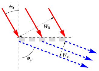
A weakly evanescent diffraction order can exist near a Rayleigh anomaly (also called Wood anomaly), where the transition from a propagating order to an evanescent order takes place. A propagating diffracted field of order can also have much larger amplitude (i.e., a large diffraction coefficient ) than the incident wave when it is close to a Rayleigh anomaly. Indeed, if and are respectively the angle of incidence and the angle of diffraction, the diffraction efficiency is less than or equal to one, so that we have . This implies that can potentially take large values when is near (grazing angle of diffraction), which means that the diffraction order is close to a Rayleigh anomaly. The high-intensity diffracted field, which can occur at a grazing angle of diffraction, can be interpreted as a spatial compression of the incident wave. This is illustrated in Fig. 1 where, for an incidence over a grating of length , the ratio of the width of a diffracted plane wave emerging from the grating to the width of the incident plane wave is equal to .
The observations in the previous paragraph suggest that a propagating diffracted wave (or a weakly evanescent diffracted wave) with enhanced field can be obtained when a grating waveguide resonance and a Rayleigh anomaly coexist. In this work, by conceptualising a photonic crystal slab as a perturbation to a uniform dielectric film, we show that the properties of the Fabry-Perot resonance can be used to design photonic crystal slabs that can diffract a substantially enhanced field into non-specular orders which are either propagating or weakly evanescent. The Fabry-Perot model for uniform dielectric films can also be used to accurately predict (especially for photonic crystal slabs with a low index contrast) the location of the resonance wavelength of a photonic crystal slab.
This work is partly motivated by the fact that photonic crystal slabs can be found on the cell wall (frustule) of some unicellular photosynthetic organisms known as diatoms Fuhrmann:APb:2004 . The biological function of these periodic photonic structures is not well understood yet Fuhrmann:APb:2004 ; Di:Caprio:JB:2012 , although it has been reported Furukawa:Protoplasma:1998 (see also Fuhrmann:APb:2004 ; Di:Caprio:JB:2012 ) that high intensity light can induce a movement of the photosynthetic units (chloroplasts) away from the cell wall toward the cell centre while a weak light can induce a movement toward the cell wall. This may suggest that the photonic crystal slabs in the diatom frustule can enhance the intensity of an incident light. In this work we will carry out some numerical simulations of a photonic crystal slab described in Fuhrmann:APb:2004 , in order to verify if it can provide an efficient field enhancement. In such a case, an enhanced field which is propagating or weakly evanescent can be beneficial since the chloroplasts is not in a direct contact with the frustule, which is located outside the cell membrane.
The combination of a Rayleigh anomaly with another optical resonance effect has been previously studied, especially for the purpose of improving the transmission efficiency. The coupling of a Rayleigh anomaly with a surface plasmon polariton Gao:OE:2009 ; McMahon:OE:2007 or a Fabry-Perot resonance Rahman:OL:2012 has been applied to improve the transmission efficiency through metallo-dielectric gratings. Optical transmission filters with a sharp peak and an improved efficiency have also been demonstrated for dielectric gratings where a guided-mode resonance and a Rayleigh anomaly coexist Amin:APL:2013 .
The grating scattering problems in this work have been solved by using a modal method Dossou:JOSAA:2012 ; Sturmberg:CPC:2016 , where the Bloch modes are computed with a finite element method Dossou:CMAME:2005 . We have observed an excellent agreement with the results computed by another finite element-based numerical technique Dossou:JCP:2006 . The modal expansion technique in Dossou:JOSAA:2012 ; Sturmberg:CPC:2016 has some similarity with the rigorous coupled wave analysis (RCWA) Moharam:JOSAA:1995 or the Fourier modal method (FMM) Li:JOSAA:1997 ; Popov:PRB:2000 , where the eigenmodes are expressed as Fourier expansions. We have developed a one-dimensional version of the modal method Dossou:JOSAA:2012 ; Sturmberg:CPC:2016 for the numerical simulation of one-dimensional photonic crystal slabs and an interesting Bloch mode treatment for one-dimensional periodic structures is also presented in Xie:OE:2006 . In many cases, by taking into account the geometry of the problem, an approximate simplified analytical model (which captures the main features of the problem) of the modal expansion technique can be developed Martin:Moreno:PRL:2001 ; Garcia:Vidal:PRB:2002 ; Garcia:Vidal:RMP:2010 ; Lalanne:JOa:2005 . These simplified models can provide some useful physical insight and, indeed, we have applied this type of treatment (effective medium technique) in this work.
In what follows, the principles behind the design of resonant photonic crystal slabs will be explained. In Section III, we will give some details on the numerical method used for the calculation of reflection and transmission through a photonic crystal slab; an effective medium technique will also be presented. The numerical simulation results of some examples of photonic crystal slabs will be given in the following section. Finally, in Section V, we will discuss some potential applications of the resonant photonic crystal slabs.
II The design principle
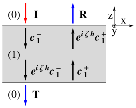
The design is based on the following principles. First, we consider the problem of plane wave incidence over a uniform dielectric slab of a finite thickness . Figure 2 presents an illustration of this problem. The dielectric slab is denoted (1) and it is surrounded by a medium (0). The refractive indices of the media (0) and (1) are respectively and . The media (0) and (1) are assumed to be lossless, i.e., and are real numbers; we also suppose that . The wavelength of the incident field is denoted . The reflection and transmission coefficients and through the slab are Born:Wolf:1999 :
| (1) |
where is the interface reflection coefficient (or Fresnel reflection coefficient) for incidence from the medium (0) into the medium (1). For incidence by a TE-polarised (or -polarised) plane wave and a TM-polarised (or -polarised) plane wave, the mathematical expressions of the reflection coefficient are respectively Born:Wolf:1999 :
| and | (2) |
The parameters and in Eq. (2) are defined as
| and | (3) |
where and is the free space wavenumber.
We note that, for both TE and TM polarisations, the interface reflection coefficient tends to one as the angle of incidence approaches the right angle, i.e., the interface transmission coefficient tends to zero as the angle of incidence approaches the right angle. This poor interface transmission can be explained by the fact that, at a grazing angle of incidence, the wavevector in the incident medium (0) is almost tangential to the interface while it can still have a significant normal component in the transmission medium (1) (from Snell’s law, the angle of refraction converges to when the angle of incidence approaches the right angle). By definition, the electric field of a TE-polarised plane wave and the magnetic field of a TM-polarised plane wave are tangential to the interface. So when the wavevector in the incident medium is almost tangential to the interface, the magnetic field of a TE-polarised plane wave and the electric field of a TM-polarised plane wave are almost perpendicular to the interface, i.e., these fields have a relatively small tangential component. But both the electric field and the magnetic of field, of the corresponding plane wave in the transmission medium (1), can still have a significant tangential component. This field mismatch results in the poor Fresnel transmission at a grazing angle of incidence.
However, with the case of plane wave incidence over a dielectric slab of a finite thickness, we can still have a 100% transmission for a grazing incidence when a Fabry-Perot resonance occurs, i.e., when in Eq. (1). So, at a Fabry-Perot resonance, there is a high transmission at a grazing incidence, despite the large field mismatch between the tangential component of a plane wave basis function of the medium (0) and the corresponding plane wave basis function in the slab. As illustrated in Fig. 2, the field inside the slab is a superposition of two counter-propagating plane waves. By using the field continuity equations at the upper and lower slab interfaces, we can show that the high transmission is due to the fact the pair of counter-propagating plane waves of the homogeneous slab interact to cancel most of the problematic tangential component (i.e., the tangential component of the -field and -field for respectively the TE and TM polarisations) at the two interfaces of the slab, thus allowing a perfect field-matching with the small tangential components of the incident and transmitted fields.
This perfect cancellation effect at a grazing incidence, of two relatively large field components inside the slab, can make the reflected and transmitted fields very sensitive to a perturbation of the field inside the slab. For an example, if the uniform dielectric slab is transformed into a photonic crystal slab (see Fig. 3), a perfect cancellation (at a Fabry-Perot resonance) cannot be expected as the modes in the slab are not plane waves. As a consequence, when the angle of incidence approaches , the perturbation to the slab field can dominate the small tangential component in the incident and transmission media. In such a situation, a strong contribution from many non-specular diffraction orders can be needed in order to match the tangential fields at either side of the slab interfaces, and it can be possible that some non-specular propagating orders get exceptionally high diffraction efficiency for a grazing incidence. We note that the results obtained here can be applied to other forms of perturbation to a uniform dielectric slab. For an example, a diffraction grating can be placed on top of the uniform dielectric film as in Liu:OME:2016 . The treatment can even be extended to non-uniform layers such as the photonic crystal gratings in Serebryannikov:PRA:2013 , whose top interface is corrugated (the photonic crystal in Serebryannikov:PRA:2013 is operated in a regime where it behaves approximately as a uniform medium).
By reciprocity (see for instance Botten:JOSAA:2000 ; Popov:book ), i.e., reversed incidence, the same photonic crystal slab can also efficiently couple light from an incident plane wave into a non-specular plane wave with a grazing angle of diffraction, and the intensity of the resulting diffracted field can be much higher than the intensity of the incident field (due to a spatial compression of the incident plane wave). It follows that the properties, of the Fabry-Perot resonance at a grazing incidence, can be used to design photonic crystal slabs which can generate a diffracted wave with a strongly enhanced field.
So far we have assumed that the incident field is a propagating incident plane wave, but the results in this section can be extending to the case of an incidence by an evanescent plane wave. The formulas Eqs. (1)-(2) are still valid for an incidence by an evanescent plane wave. But here the coefficient in Eq. (3) is a purely imaginary complex number while remains a real number (it is assumed that ). In particular we have , so that the denominator term of the reflection and transmission coefficients and , in Eq. (1), becomes zero when we have the resonance condition , with . This resonance condition is often called guided-mode resonance because the guided modes of a planar waveguide also satisfy the same condition Marcuse:book:1974 . By considering the situation where the purely imaginary complex number approaches zero, and by repeating the arguments used for an incidence by a propagating plane wave, we can design a photonic crystal slab which can enhance the magnitude of a diffracted evanescent field.
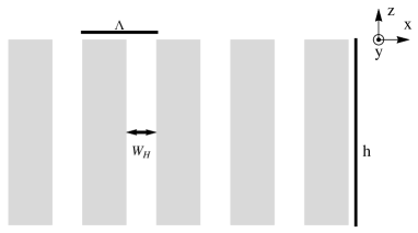
III Reflection and transmission through a photonic crystal slab
We now give some details on the modelling of light transmission through a photonic crystal slab. We consider the one-dimensional photonic crystal slab shown in Fig. 3. It has a period in the -direction, is invariant with respect to and has a finite thickness in the -direction. The photonic crystal slab consists of an array of holes (of width and refractive index ) in a medium of refractive index and the refractive index of the upper and lower semi-infinite media is . When a plane wave, with a wavevector , is incident on a photonic crystal slab, the reflected and transmitted fields can be written as a superposition of plane waves with wavevector , where is the diffraction order and the coefficients and are defined as
| and | (4) |
By using the fact that the photonic crystal slab in Fig. 3 can be modelled as a periodic array of -invariant waveguides, we can write the field inside the slab as a superposition of counter-propagating waveguide modes Dossou:JOSAA:2012 ; Sturmberg:CPC:2016 . This modal expansion is a generalisation of the treatment for a uniform dielectric film, but here the modal expansion involves a multitude of counter-propagating pairs of modes. A Bloch mode of the array of cylinders is quasi-periodic with respect to the coordinate, i.e., , and has an exponential dependence with respect to the coordinate. The modes of the array and their propagation constant can be computed using a one-dimensional version of the finite element method in Dossou:CMAME:2005 .
The field continuity conditions at the upper and lower interface of the slab can be transformed into a system of linear equations Dossou:JOSAA:2012 by projecting the modal expansion on either side of an interface onto a set of test functions (adjoint modes). The coefficients of the modal expansions can be obtained by solving this linear system. The projection involves some overlap integrals between the modes of media (0) and (1). For an example, let denotes the upper interface of a unit cell of the array. If is at the position , an overlap integral between a plane wave of the medium (0) and a mode of the medium (1) can be defined as (see Eq. (64) of Dossou:JOSAA:2012 ):
| (5) |
with
| (6) | |||||
| (7) |
For the examples considered in this work, the index contrast of the photonic crystal slab is relatively small and the wave propagation inside the slab is typically dominated by a single pair of counter-propagating modes. If is the propagation constant of the dominant mode, by analogy with a plane wave with a wavevector , we can define an average refractive index of the photonic crystal slab as
| (8) |
The value of the average refractive index depends on the wavelength and on the polarisation state. If, for an incident wavelength , the phase is an integer multiple of , a Fabry-Perot resonance will occur for an incidence over a uniform dielectric slab of refractive index and the photonic crystal slab will typically display a resonant behaviour at a wavelength near . Thus the homogenised slab can be used to predict the approximate location of the resonant wavelengths of the photonic crystal slab.
For an incidence by a propagating plane wave, by using Eq. (8), we can express the resonance condition , with , as:
| (9) |
Thus for given values of , , and , we can easily find a thickness corresponding to a resonance.
For an incidence by an evanescent plane wave, the resonance condition can be transformed into equations which are identical to the eigenvalue equation for the guided modes of a planar waveguide Wang:AO:1993 ; Marcuse:book:1974 . For the TE and TM-polarisations we have respectively
| (10) | |||||
| (11) |
with .
For the case of a grazing angle of incidence, as stated above, other modes, which are different from the ones used in the resonance condition Eq. (9) or Eqs. (10)-(11), can also play a non-negligible role. As a consequence, the peak reflectance or transmittance wavelength of the photonic crystal slab, with a thickness given by Eq. (9) or Eqs. (10)-(11), can be shifted to the left or right side of the peak reflectance or transmittance wavelength of the uniform dielectric film of same thickness and a refractive index (see Figs. 4 and 5 for an example). As we now explain, the direction of the shift depends essentially on the phase of the photonic crystal modes near the resonance wavelength of the uniform slab. In order to model the plane wave scattering by a photonic crystal slab, a matrix form of the scalar reflection and transmission coefficients in Eq. (1) must be used and they can be represented as (Dossou:JOSAA:2012, , see Eqs. (81) and (82)):
| (12) | |||||
| (13) |
where is the diagonal matrix which describes the propagation of the Bloch mode inside the photonic crystal slab with a thickness and , are the Fresnel scattering matrices between the medium (0), i.e., the free space and the medium (1), i.e., the photonic crystal. In the examples studied in this paper, the wave scattering can be accurately modelled by using the plane waves of orders and (they are the only propagating diffraction orders). If we truncate the plane wave basis of the medium (0) to the two plane wave functions of diffraction orders 0 and -1, and select the two Bloch modes of medium (1) which match (have highest overlap) these two plane wave functions as basis functions for medium (1), then the matrices in Eqs. (12) and (13) become matrices. In particular, for incidence from the specular order , the reflection coefficient and the transmission coefficient into the order are (here is set to ):
| (14) | |||
The terms , and which appear at the numerators or the denominators of Eq. (14) are null when the off-diagonal coefficients of the scattering matrices , are zeros, in such a case we can verify that Eq. (14) is equivalent to Eq. (1). Otherwise, the location of the maximum in reflectance or transmittance is largely determined by the denominator of and . Here we have
| (15) | |||
If the value of is a real number near the resonance wavelength of the uniform dielectric slab, we have observed that the resonance wavelength of the photonic crystal slab will closely match that of the uniform slab. Otherwise, depending on the phase of , the resonance wavelength of the photonic crystal slab moves to the left or right side of the resonance wavelength of the uniform dielectric slab.
IV Numerical simulations
For the numerical calculations, we first consider the example of a one-dimensional photonic crystal slab which has same lattice constant and filling ratio as a two-dimensional square array of holes described in Fuhrmann:APb:2004 , where the photonic crystal structures found in the cell wall (frustule) of the marine diatom Coscinodiscus granii have been analysed. We will also analyse a two-dimensional photonic crystal slab later in this section. The lattice constant of the two-dimensional square array is and the hole radius is . The slab is made of silica, with a refractive index . The slab is surrounded by water and the holes are filled with water (refractive index ). The filling ratio of the two-dimensional array of holes with a square lattice is . The filling ratio of the corresponding one-dimensional photonic crystal (see Fig. 3) is , where is the width of the holes. We have if . For the numerical simulations, we have rounded the value of to .
For an illustration of the derivations presented in Section III, we want to find a thickness of the photonic crystal slab such that a Fabry-Perot resonance occurs at a grazing angle of incidence (e.g., ) near the wavelength (blue colour spectrum). This value of the wavelength is chosen because diatoms can display high photosynthetic activity in the blue and red regions of the spectrum Kirk:book . It is also said in Fuhrmann:APb:2004 that the diatom frustule slab, with a square lattice array, has a thickness between 200 and 600 nm, and, as we shall see, this range includes the slab thickness where a Fabry-Perot resonance occurs at the wavelength . Note however that we have observed the behaviours described below at other wavelengths. For an incidence by a TE-polarised plane wave, we have found that the propagation constant of the Bloch mode of the periodic array, which has the highest overlap Eq. (5) with the incident plane wave, is . Since , according to Eq. (8), the average refractive index (at the wavelength ) of the photonic crystal is . We can then obtain the resonance thickness from Eq. (9): , where the parameter in Eq. (9) is set to . With the case of an incidence by a TM-polarised plane wave, we have , , so that the computed resonance thickness is . We have used the thickness value for the calculations.
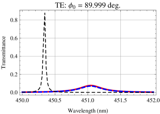
Figure 4 shows the transmittance through the photonic crystal slab of thickness for the angles of incidence , , and , for TE-polarisation. The corresponding results for the TM-polarisation are plotted in Fig. 5. In Figs. 4 and 5, the thick continuous red curves and the thick dashed blue curves represent respectively the total transmittance and the diffraction efficiency (in transmission) into the order . The thin dashed black curves are the transmittance (the transmission coefficient is given by Eq. (1)) through a uniform slab of refractive index and same thickness as the photonic crystal slab. In all cases, the transmission peak occurs at a wavelength which is close to the design wavelength . The transmittance of the photonic crystal slab is very close to that of the uniform slab at the angle of incidence . But when approaches the right angle, as predicted in Section II, the response of the photonic crystal slab deviates from that of the uniform slab. In particular, the proportion of power carried by the first diffraction order starts to increase substantially. As explained in Section II, by reversing the direction of the diffracted plane wave, we can also expect an efficient transmission into a grazing angle of diffraction.
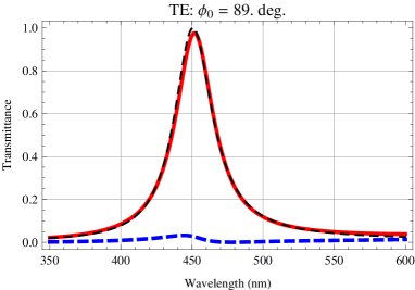
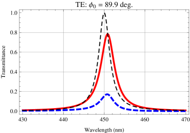
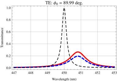
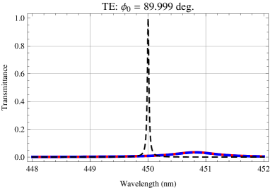
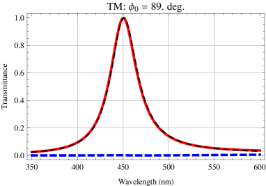
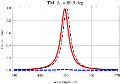
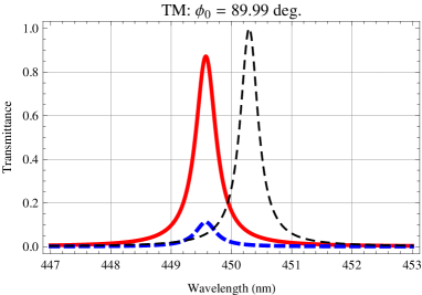
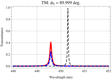
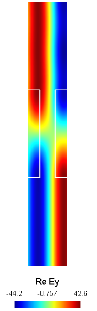
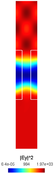
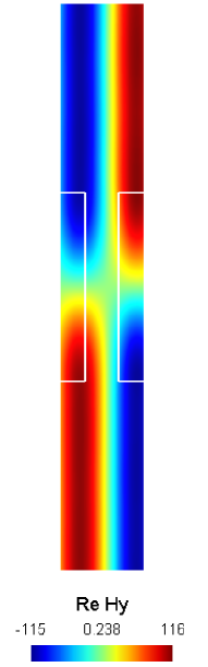
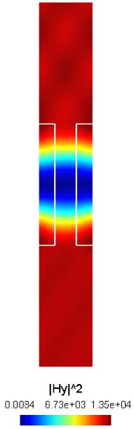
Let us show an example of field enhancement. In Figs. 4 and 5, the peak diffraction efficiency at the incidence angle is (at the wavelength 450.8 nm) for the TE-polarisation and (at the wavelength 449.6 nm) for the TM-polarisation. The angle of diffraction at the peak diffraction efficiency is for TE-polarisation and for the TM-polarisation. We recall that the angle of diffraction into an order is . The transmission coefficients for the TE and TM-polarisations are, respectively, and . For the reversed incidence, by reciprocity, the diffraction efficiency is unchanged but the transmission coefficient becomes and their values are relatively large: for the TE-polarisation (the corresponding field plots of and are shown in Fig. 6) and for the TM-polarisation (the corresponding field plots of and are shown in Fig. 7). The field plots in Figs. 6 and 7 show respectively the total field components (for an incidence by a TE-polarised plane wave with a unit amplitude ) and (for an incidence by a TM-polarised plane wave with a unit amplitude ). In Figs. 6 and 7, the white lines indicate the interfaces (over a unit cell) between the background material (silica) and the surrounding medium (water). Above the slab unit cells, the periodic features, which can be seen in the field plots of and , are caused by the interference between the incident plane wave and the diffracted plane waves of orders 0 and -1. Below the unit cell, the interference between the transmitted plane waves of orders 0 and -1 is weaker because the transmission coefficient into the specular order has a relatively small value. The results presented here are an interesting confirmation that a photonic crystal slab can be designed to increase the intensity of an incident plane wave by an extremely large factor (here we have an example where the factor is above ). This is also consistent with the results in Amin:APL:2013 , in particular the field plot in Fig. 3(c) of Amin:APL:2013 shows that the orders and are propagating at a high grazing angle and the amplitude of their field is about 10 times larger than the amplitude of the incident plane wave. A giant field enhancement factor of about in photonic crystal slab is also reported in Mocella:PRB:2015 , again, for a wavelength near a Rayleigh anomaly.
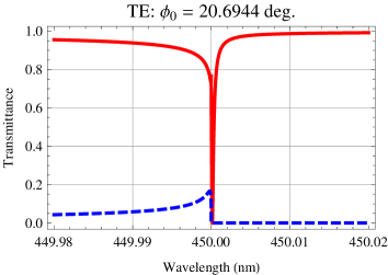
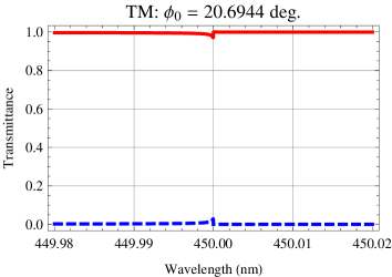
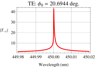
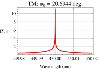
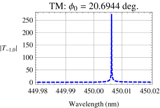
With the reversed case, the angle of incidence depends on the wavelength. However, in order to study the wavelength dependence of the quantities and , it would be convenient to analyse a problem with a fixed angle of incidence. Here we will use a reversed incident angle associated with the design wavelength : the angle of diffraction at a high grazing angle can be approximated as . The curves of the total transmittance (continuous red curves) and the diffraction efficiency (dashed blue curves) at the angle of incidence are plotted in Fig. 8. The transmission coefficient corresponding to the diffraction efficiency is shown in Fig. 9. The angle of incidence is chosen such that the Rayleigh anomaly for the order occurs near the wavelength and the slab thickness is chosen such that the order is in a Fabry-Perot resonance with a mode of the photonic crystal slab. The results in Fig. 9 indicate that, with a Fabry-Perot resonance near a Rayleigh anomaly, a photonic crystal slab can generate a grazing propagating diffracted field (for ) or a weakly evanescent diffracted field (for ) with an amplitude that is much higher than the amplitude of the incident light.
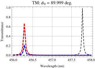
Finally, we also analyse a case of a photonic crystal slab with the two-dimensional square lattice array of holes Fuhrmann:APb:2004 whose parameters were given earlier in this section. At the wavelength , the average refractive index for the TE and TM-polarisations are, respectively, and . For the homogenised dielectric slab, the Fabry-Perot resonance at high grazing angle of incidence occurs at the slab thickness (TE-polarisation) and (TM-polarisation). The relative difference between these two thickness values is about 1.6% (in the case of the one-dimensional photonic crystal slab, the relative difference is 0.065%) and so the two-dimensional photonic crystal slab can be expected to exhibit a higher sensitivity to polarisation. For the numerical calculation, the slab thickness is set to , which is close to the resonance thickness for the TE-polarisation. Figure 10 shows the total transmittance and the diffraction efficiency into the order , for the high grazing incidence angle . The peak transmittance wavelengths for the TE and TM-polarisations are, respectively, 451.1 nm and 456.3 nm.
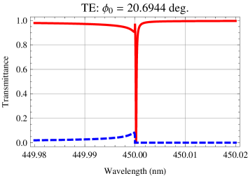
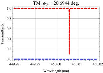
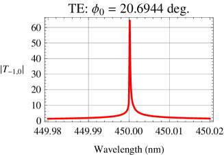
With the two-dimensional photonic crystal slab, we can also generate an enhanced diffracted field by combining the Fabry-Perot resonance with the Rayleigh anomaly. A Rayleigh anomaly exists for the order , near the wavelength , when the angle of incidence is set to . The slab thickness is chosen such that the wavelength is close to a Fabry-Perot resonance for the TE-polarisation. We have plotted the total transmittance (continuous red curves) and the diffraction efficiency into the order (dashed blue curves) in Fig. 11 while the curves of the transmission coefficient are shown in Fig. 12. We have a large transmission coefficient for the TE-polarisation around the design wavelength . The peak transmission coefficient for the TM-polarisation occurs in a wavelength band (centred around ) where the order is evanescent. This deviation from the operating wavelength can be explained by the fact the slab thickness is not close enough to the calculated resonance thickness for the TM-polarisation. Actually, since the order is evanescent at the wavelength , the corresponding resonance thickness must be determined from the guided-mode resonance conditions Eqs. (10)-(11) for incidence by an evanescent plane wave. By using the average refractive index and , respectively, for the TE and TM-polarisations, and by applying Eqs. (10)-(11), we can obtain the following guided-mode resonance thickness (at the wavelength ): for the TE-polarisation and for the TM-polarisation. Indeed, for the TM-polarisation the resonance thickness is relatively close to the thickness used for the calculations in Figs. 11 and 12 and this can explain why we have a guided-mode resonance for the TM-polarisation.
V Potential applications
The results in Section IV show that, when a non-specular order is resonantly coupled to a photonic crystal slab mode near a Rayleigh anomaly, the corresponding diffraction coefficient can take very large values as the incident wavelength approaches the Rayleigh anomaly wavelength. This property can be applied to design photonic crystal slabs which can increase the intensity of an incident plane wave by a large factor. The diffracted enhanced field is either propagating at a grazing angle or weakly evanescent.
For most common gratings, the diffraction coefficient of a non-specular order typically takes very small values as its angle of diffraction approaches . When little energy is available, it is not possible to fully take advantage of the fact that diffraction gratings can exhibit an arbitrarily large angular dispersion near a Rayleigh anomaly. But, with the resonant cases illustrated in Figs. 9 and 12, it can make sense to consider the properties of a diffracted wave in the limit where an incident wavelength is arbitrarily close to the Rayleigh anomaly wavelength.
As an example, for a given incident ray and when a grating is rotating, the angle of incidence of the ray at a time will change with an angular velocity denoted . For a propagating diffraction order , the diffracted wave will rotate at an angular speed . By taking the time-derivative of the grating equation , at a fixed wavelength, the angular velocity can be expressed in term of as . This shows that the angular velocity of a non-specular diffracted ray increases toward infinity as the angle of diffraction approaches . Such a fast moving ray can potentially shift the frequency of the incident light substantially. The frequency shift can be analysed by using a Doppler shift formula since the diffracted light behaves like (or simulates) the light emitted from a surface which is rotating at the angular velocity Dossou:AO:2016 . Interestingly, diatoms can exhibit some oscillatory (or rotational) motion when subjected to water flows Karp:LO:1998 ; Srajer:ABC:2009 ; Gutierrez:PB:2014 , which has some similarity with the tendency of plant leaves to oscillate under the wind. Such an oscillation has the potential to strongly shift an incident frequency near a Rayleigh anomaly (when it is coupled with a Fabry-Perot resonance). However, at this time, it is not possible to know if such a frequency shift is relevant to the photosynthetic processes in diatoms.
VI Conclusion
Photonic crystal slabs can be designed to enhance the intensity of an incident plane wave by an extremely large factor. Although we have only studied the case of a light transmission, the generalisation of the main results to a light reflection is straightforward. We have given a clear physical explanation, based on the properties of the Fabry-Perot resonance and the Rayleigh anomaly, for the origin of this enhancement effect. By applying the physical interpretations, we have developed an effective medium technique which can be used to efficiently design a photonic crystal slab, with a resonance wavelength near a given value. For the case of a scattering into a propagating diffracted order, the field magnification is due to a spatial compression of the incident wave and so the diffracted field propagates at a grazing angle of diffraction. The numerical results also suggest that the photonic crystal slabs found in diatom frustules can produce a substantially enhanced field and it will be interesting to investigate the significance of this enhancement to the photosynthetic processes in diatoms.
The combination of the Fabry-Perot resonance with the Rayleigh anomaly implies that a non-specular diffraction order can still transmit or reflect an intense light, for incident wavelengths which are extremely close to the Rayleigh anomaly wavelength. This opens up the possibility of an efficient operation of a diffraction grating in the limit where an incident wavelength is arbitrarily close to a Rayleigh anomaly wavelength, a regime where diffraction gratings have an extremely large angular dispersion, e.g., with respect to the incident wavelength or the incidence angle. For an example, a rotation of the grating at a moderate angular speed can induce a diffracted field which rotates with an extremely large angular velocity, and this in turn can produce a relatively large frequency shift.
Acknowledgments
This research was supported by the Australian Research Council (ARC) (project number CE110001018).
References
- (1) A. Hessel and A. A. Oliner, “A new theory of Wood’s anomalies on optical gratings,” Appl. Opt., vol. 4, no. 10, pp. 1275–1297, 1965.
- (2) D. L. Mills and M. Weber, “Enhanced electric fields near gratings: Comments on enhanced Raman scattering from surfaces,” Phys. Rev. B, vol. 26, pp. 1075–1078, 1982.
- (3) M. Weber and D. L. Mills, “Interaction of electromagnetic waves with periodic gratings: Enhanced fields and the reflectivity,” Phys. Rev. B, vol. 27, pp. 2698–2709, 1983.
- (4) N. Garcia, “Exact calculations of p-polarized electromagnetic fields incident on grating surfaces: Surface polariton resonances,” Opt. Commun., vol. 45, no. 5, pp. 307–310, 1983.
- (5) N. García, G. Díaz, J. Saénz, and C. Ocal, “Intensities and field enhancement of light scattered from periodic gratings: study of ag, au and cu surfaces,” Surface Science, vol. 143, no. 2–3, pp. 342–358, 1984.
- (6) H. Gao, J. M. McMahon, M. H. Lee, J. Henzie, S. K. Gray, G. C. Schatz, and T. W. Odom, “Rayleigh anomaly-surface plasmon polariton resonances in palladium and gold subwavelength hole arrays,” Opt. Express, vol. 17, no. 4, pp. 2334–2340, 2009.
- (7) S. S. Wang and R. Magnusson, “Theory and applications of guided-mode resonance filters,” Appl. Opt., vol. 32, no. 14, pp. 2606–2613, 1993.
- (8) D. Rosenblatt, A. Sharon, and A. A. Friesem, “Resonant grating waveguide structures,” IEEE J. Quantum Electron., vol. 33, no. 11, pp. 2038–2059, 1997.
- (9) M. Siltanen, S. Leivo, P. Voima, M. Kauranen, P. Karvinen, P. Vahimaa, and M. Kuittinen, “Strong enhancement of second-harmonic generation in all-dielectric resonant waveguide grating,” Appl. Phys. Lett., vol. 91, no. 11, p. 111109, 2007.
- (10) W. Zhang and B. T. Cunningham, “Fluorescence enhancement by a photonic crystal with a nanorod-structured high index layer,” Appl. Phys. Lett., vol. 93, no. 13, p. 133115, 2008.
- (11) M. Laroche, S. Albaladejo, R. Carminati, and J. J. Sáenz, “Optical resonances in one-dimensional dielectric nanorod arrays: field-induced fluorescence enhancement,” Opt. Lett., vol. 32, no. 18, pp. 2762–2764, 2007.
- (12) R. Gómez-Medina, M. Laroche, and J. J. Sáenz, “Extraordinary optical reflection from sub-wavelength cylinder arrays,” Opt. Express, vol. 14, no. 9, pp. 3730–3737, 2006.
- (13) T. Fuhrmann, S. Landwehr, M. El Rharbi-Kucki, and M. Sumper, “Diatoms as living photonic crystals,” Applied Physics B, vol. 78, no. 3, pp. 257–260, 2004.
- (14) G. Di Caprio, G. Coppola, L. D. Stefano, M. D. Stefano, A. Antonucci, R. Congestri, and E. D. Tommasi, “Shedding light on diatom photonics by means of digital holography,” J. Biophotonics, vol. 7, no. 5, pp. 341–350, 2014.
- (15) T. Furukawa, M. Watanabe, and I. Shihira-Ishikawa, “Green- and blue-light-mediated chloroplast migration in the centric diatom Pleurosira laevis,” Protoplasma, vol. 203, no. 3, pp. 214–220, 1998.
- (16) J. M. McMahon, J. Henzie, T. W. Odom, G. C. Schatz, and S. K. Gray, “Tailoring the sensing capabilities of nanohole arrays in gold films with Rayleigh anomaly-surface plasmon polaritons,” Opt. Express, vol. 15, no. 26, pp. 18 119–18 129, 2007.
- (17) A. T. M. A. Rahman, P. Majewski, and K. Vasilev, “Extraordinary optical transmission: coupling of the Wood-Rayleigh anomaly and the Fabry-Perot resonance,” Opt. Lett., vol. 37, no. 10, pp. 1742–1744, 2012.
- (18) M. Shyiq Amin, J. Woong Yoon, and R. Magnusson, “Optical transmission filters with coexisting guided-mode resonance and Rayleigh anomaly,” Appl. Phys. Lett., vol. 103, no. 13, p. 131106, 2013.
- (19) K. B. Dossou, L. C. Botten, A. A. Asatryan, B. C. P. Sturmberg, M. A. Byrne, C. G. Poulton, R. C. McPhedran, and C. M. de Sterke, “Modal formulation for diffraction by absorbing photonic crystal slabs,” J. Opt. Soc. Am. A, vol. 29, no. 5, pp. 817–831, 2012.
- (20) B. C. Sturmberg, K. B. Dossou, F. J. Lawrence, C. G. Poulton, R. C. McPhedran, C. M. de Sterke, and L. C. Botten, “EMUstack: An open source route to insightful electromagnetic computation via the Bloch mode scattering matrix method,” Comput. Phys. Commun., vol. 202, pp. 276–286, 2016.
- (21) K. Dossou and M. Fontaine, “A high order isoparametric finite element method for the computation of waveguide modes,” Comput. Methods Appl. Mech. Engrg., vol. 194, no. 6-8, pp. 837–858, 2005.
- (22) K. Dossou, M. A. Byrne, and L. C. Botten, “Finite element computation of grating scattering matrices and application to photonic crystal band calculations,” J. Comput. Phys., vol. 219, no. 1, pp. 120–143, 2006.
- (23) M. G. Moharam, T. K. Gaylord, E. B. Grann, and D. A. Pommet, “Formulation for stable and efficient implementation of the rigorous coupled-wave analysis of binary gratings,” J. Opt. Soc. Am. A, vol. 12, no. 5, pp. 1068–1076, 1995.
- (24) L. Li, “New formulation of the Fourier modal method for crossed surface-relief gratings,” J. Opt. Soc. Am. A, vol. 14, no. 10, pp. 2758–2767, 1997.
- (25) E. Popov, M. Nevière, S. Enoch, and R. Reinisch, “Theory of light transmission through subwavelength periodic hole arrays,” Phys. Rev. B, vol. 62, pp. 16 100–16 108, 2000.
- (26) Y. Xie, A. R. Zakharian, J. V. Moloney, and M. Mansuripur, “Optical transmission at oblique incidence through a periodic array of sub-wavelength slits in a metallic host,” Opt. Express, vol. 14, no. 22, pp. 10 220–10 227, 2006.
- (27) L. Martín-Moreno, F. J. García-Vidal, H. J. Lezec, K. M. Pellerin, T. Thio, J. B. Pendry, and T. W. Ebbesen, “Theory of extraordinary optical transmission through subwavelength hole arrays,” Phys. Rev. Lett., vol. 86, pp. 1114–1117, 2001.
- (28) F. J. García-Vidal and L. Martín-Moreno, “Transmission and focusing of light in one-dimensional periodically nanostructured metals,” Phys. Rev. B, vol. 66, p. 155412, 2002.
- (29) F. J. Garcia-Vidal, L. Martin-Moreno, T. W. Ebbesen, and L. Kuipers, “Light passing through subwavelength apertures,” Rev. Mod. Phys., vol. 82, pp. 729–787, 2010.
- (30) P. Lalanne, J. C. Rodier, and J. P. Hugonin, “Surface plasmons of metallic surfaces perforated by nanohole arrays,” J. Opt. A, vol. 7, no. 8, pp. 422–426, 2005.
- (31) M. Born and E. Wolf, Principles of optics: Electromagnetic theory of propagation, interference and diffraction of light, 7th ed. Cambridge, UK: Cambridge University Press, 1999.
- (32) F. Liu and X. Zhang, “Contrast- and intensity-enhancement of sensor signals based on Rayleigh anomaly in metal-coated gratings,” Opt. Mater. Express, vol. 6, no. 2, pp. 682–690, 2016.
- (33) A. E. Serebryannikov and E. Ozbay, “One-way Rayleigh-Wood anomalies and tunable narrowband transmission in photonic crystal gratings with broken structural symmetry,” Phys. Rev. A, vol. 87, p. 053804, 2013.
- (34) L. C. Botten, N.-A. P. Nicorovici, A. A. Asatryan, R. C. McPhedran, C. M. de Sterke, and P. A. Robinson, “Formulation for electromagnetic scattering and propagation through grating stacks of metallic and dielectric cylinders for photonic crystal calculations. Part II. Properties and implementation,” J. Opt. Soc. Am. A, vol. 17, no. 12, pp. 2177–2190, 2000.
- (35) E. Popov, Ed., Gratings: Theory and Numeric Applications, 2nd ed. Marseille, France: Institut Fresnel, 2014.
- (36) D. Marcuse, Theory of dielectric optical waveguides. New York: Academic Press, 1974.
- (37) J. T. O. Kirk, Light and Photosynthesis in Aquatic Ecosystems, 3rd ed. Cambridge, UK: Cambridge University Press, 2011.
- (38) V. Mocella and S. Romano, “Giant field enhancement in photonic resonant lattices,” Phys. Rev. B, vol. 92, p. 155117, 2015.
- (39) K. B. Dossou, “Doppler shift generated by a moving diffraction grating under incidence by polychromatic diffuse light,” Appl. Opt., vol. 55, no. 15, pp. 3915–3924, 2016.
- (40) L. Karp-Boss and P. A. Jumars, “Motion of diatom chains in steady shear flow,” Limnology and Oceanography, vol. 43, no. 8, pp. 1767–1773, 1998.
- (41) J. Srajer, B. Majlis, and I. Gebeshuber, “Microfluidic simulation of a colonial diatom chain reveals oscillatory movement,” Acta Botanica Croatica, vol. 68, no. 2, pp. 431–441, 2009.
- (42) B. Gutiérrez-Medina, A. J. Guerra, A. I. P. Maldonado, Y. C. Rubio, and J. V. G. Meza, “Circular random motion in diatom gliding under isotropic conditions,” Physical Biology, vol. 11, no. 6, p. 066006, 2014.