Extension of Friedel’s law to Vortex Beam Diffraction
Abstract
Friedel’s law states that the modulus of the Fourier transform of real functions is centrosymmetric, while the phase is antisymmetric. As a consequence of this, elastic scattering of plane wave photons or electrons within the first-order Born-approximation as well as Fraunhofer diffraction on any aperture, is bound to result in centrosymmetric diffraction patterns. Friedel’s law, however, does not apply for vortex beams, and centrosymmetry in general is not present in their diffraction patterns. In this work we extend Friedel’s law for vortex beams by showing that the diffraction patterns of vortex beams with opposite topological charge, scattered on the same two dimensional potential, always are centrosymmetric to one another, regardless of the symmetry of the scattering object. We verify our statement by means of numerical simulations and experimental data. Our research provides deeper understanding in vortex beam diffraction and can be used to design new experiments to measure the topological charge of vortex beams with diffraction gratings, or study general vortex beam diffraction.
I Introduction
Friedel’s law (FL) states that two antisymmetric points in the Fourier transform of a real function are complex conjugated to one another, . By deriving this rule, the French crystallographer George Friedel was able to explain why, within the kinematical approximation, the zeroth order Laue zone in X-Ray diffraction patterns, always are centrosymmetric and showed how this puts restrictions on the possible crystal symmetries that can be directly determined by X-ray diffraction Friedel1913 . Not only does FL apply to X-ray diffraction on crystals, it generally is valid for all scattering processes where a plane wave scatters on (approximately) two dimensional objects that are described by a real transmittance function, such as apertures or gratings. Whereas for electron diffraction on crystals, FL breaks down relatively fast because of dynamical scattering, it remains valid for electrons scattered on apertures. Since FL only is valid for plane waves, the diffraction patterns of distorted or modified beams, like the so-called vortex beams, do not necessarily follow this rule.
Vortex beams are eigenstates of the orbital angular momentum (OAM) operator, Nye1974 and their wavefunction has the form
| (1) |
with and the radial and the azimuthal coordinate with respect to the wave propagation axis, . The number , is called the topological charge (TC) of the vortex. Since vortex beams are a eigenstates of the angular momentum operator, they possess a well-defined angular momentum of per photonAllen1999 , electronBliokh2007 or any other particleClark2015 described by the wave function in eq. 1. These beams have a typical donut-like intensity profile, a bright ring with a black spot in the middle, that arises from the phase singularity at its center. Since their first experimental demonstration in optics Bazhenov1990 , they have been studied extensively, both theoretically and experimentally, which has led to numerous applications in fields such as nano-manipulation Luo ; He ; Friese , astrophysics Foo2005 ; Swartzlander2007 ; Serabyn2010 ; Berkhout2008 and telecommunications andrewsbook ; wangterabit ; vortexnot . Although slightly more complicated, a vast amount of methods have been developed to produce vortex beams in an electron microscope Uchida2010 ; Verbeeck2010 ; Clark2013 ; Beche2013 as well and several studies suggest their use to probe magnetism Verbeeck2010 ; Juchtmans2016a , nano-manipulation Verbeeck2013 , spin-polarization devices Karimi2012 and measuring the chirality of crystals Juchtmans2015 . Additionally, the expression in eq. 1 provides an excellent mathematical basis to describe scattering on helical crystals Juchtmans2015a or processes involving local exchange of OAMJuchtmans2015b .
Many of the above applications, require an accurate measurement of the TC of the vortex beam. A popular way of doing this, is by studying the vortex diffraction patterns of specially designed apertures such as triangular apertures Hickmann2010 ; Guzzinati2014b or multi-pinhole plates Guo2009 ; Shi2012 ; Clark2014 . In this work we elaborate on the observation made in these studies that diffraction patterns of vortex beams with opposite TC always seem to be centrosymmetric or equivalently, rotated rad, with respect to each other, independent from the shape of the aperture. Although in the above research, this can be explained using the symmetry of these specific apertures, we will formulate an extension of FL as a more fundamental property of vortex beam diffraction. We illustrate with numerical simulations and experiments, that even for non-symmetric scattering processes, the two-fold rotational symmetry between diffraction patterns with oppositely charged vortex beams, remains present. This research provides further insights in vortex beam diffraction and can help to optimize methods to measure the TC of vortex beams using diffraction gratings or study general vortex beam diffraction.
II Theoretical formulation
II.1 Friedel’s law for plane waves
Friedel’s law (FL) includes two properties of the Fourier transform (FT) of real functionsFriedel1913 .
Given a real function , its FT is given by
| (2) |
Looking at the complex conjugate of the FT,
| (3) |
one can easily see that the modulus of the FT is centrosymmetric,
| (4) |
while its phase, , is antisymmetric,
| (5) |
Eq. (4) and (5) are known as Friedel’s law and any set of centrosymmetric points is called a Friedel pair.
Friedel applied these properties to describe the symmetries seen in X-ray diffraction patterns on crystals. For a scalar plane wave photon, that is scattered kinematically by a crysal, the scattering potential is a real function. Within the single scattering approximation, valid for weakly interacting samples, the scattering amplitude of a plane wave photon, with wavenumber , to scatter to a plane wave with wavenumber , then is given by
| (6) |
with . Clearly, the scattering amplitude exactly equals the FT of the potential. The X-ray diffraction pattern is given by the intersection of the three dimensional scattering amplitude with the so-called Ewald sphere, which assures that the length of the wave vector of the outgoing photon, and thus the energy, is the same as that of the incoming photon DeGraef2003 . In general, the curvature of this sphere can be considered flat for any relevant scattering angle, and the scattering amplitude is determined by the two dimensional FT of the potential projected along the -axis, the photon’s propagation axis, ,
| (7) |
where here, and in the following, denotes the two dimensional coordinate in the plane. The diffraction patterns in the kinematical approximation, given by the scattering amplitude squared , will be centrosymmetric because of FL, making it impossible to distinguish certain symmetries in the projection of crystals with one single diffraction pattern. A crystal with a three-fold rotation axis along the projection direction, for instance, will show the same symmetry in its diffraction pattern as a crystal with a six-fold rotation axis Friedel1913 .
Besides X-ray diffraction on crystals, FL also applies to diffraction of plane waves on apertures and gratings. Consider, for instance, an aperture in the -plane that is placed at , illuminated by a plane wave of the form . The diffracted wave in the far–field of the aperture then is given by the Fraunhofer equation Born1999
| (8) |
with , te distance from the aperture and the transmittance function of the grating. In general does not have to be real. In case of phase plates, for instance, where the phase of the wave is altered, is complex. But for apertures that only change the amplitude, is real. In this case it is clear we can apply Friedel’s law and the intensity pattern of the diffracted wave will always be centrosymmetric, independently from the symmetry of the diffraction grating. This is shown numerically and experamentally in fig. 1.
II.2 Friedel’s law for vortex beams
Friedel’s law only applies to diffraction of plane waves. When the incoming beam is modified or distorted, it is no longer valid. This is the case for an incoming vortex beam of the form
| (9) |
where is the topological charge and is the radial profile of the beam at height . The symmetry of the diffraction pattern of such a beam scattered on an aperture or crystal in general will not be centrosymmetric anymore, see fig. 1, fig. 2 and fig. 3. However, applying the same trick as in eq. 3, we can easily find a relation between the diffraction patterns of vortex beams with opposite topological charge having the same real radial profile.
Consider scattering of a vortex beam on an aperture with real transmittance function placed at height . Similar to eq. 8, the wave in the far–field now is given by the Fraunhofer equation
| (10) |
When we look at the complex conjugate of the scattered wave, we get
| (11) |
This means that diffraction patterns of oppositely charged vortex probes with a real radial profile, will be centrosymmetric, or rotated rad, with respect to each other. The same goes for diffraction on a crystal when replacing the incoming plane wave in eq. 6 by a vortex beam. Note that the radial profile of the beam has to be real, as is the case for most typical vortex beams such as the non-diffracting Bessel beams, , or the Laguerre Gaussian beams in the focal plane, , where is the Laguerre polynomial with radial and angular mode and respectively and is a parameter determining the with of the beam. Note that when defocussing vortex beams with a real radial function, it becomes complex and eq. 11 no longer holds.
We will refer to eq. 11 as the extension of Friedel’s law (EFL) applicable for vortex beams. It includes the known Friedel’s law when considering a plane wave as a vortex beam with topological charge .
III Simulation and experiment
In this section, we show simulations of vortex beam diffraction on a multi-pinhole and a triangular aperture and compare these with electron vortex beam experiments on a probe-corrected FEI Titan3 microscope. The incoming vortex wave with TC, , numerically is simulated by:
| (12) |
with , . Here is the wavelength of the incoming beam and is the convergence angle, an experimental parameter determining the spot size. In our simulations and experiments we make use of a 300 keV electron beam, pm-1 with a semi–convergence angle rad. Eq. 12 reflects the experimental setup of a vortex beam that is generated by evenly illuminating the condenser aperture while giving it an extra vortex phase, after which the probe is formed in the far–field of this aperture. For photons, this phase can be applied with, for instance, a spatial light modulator Bouchal2005 , while for electrons, this can be realized by placing the tip of a magnetized needle on the center of the condenser aperture Beche2013 . In our experiment, however, the electron vortex beams are created by placing a fork hologram in the illumination system Verbeeck2010 . The condenser system then is used to project the FT of the hologram in the sample plane and the vortex probe in eq. 12 is obtained. For practical reasons, the triangular and multi-pinhole apertures were placed in the selected area plane which is conjugated to the image plane. Note that the experiments are done using an electron microscope, but the result is equally valid for optical vortex diffraction.
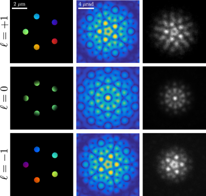
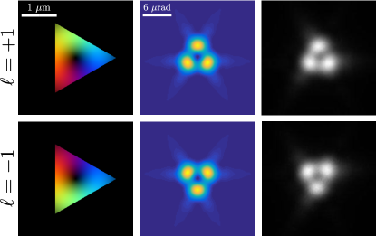
In fig. 1, the real space image of a vortex beam with , and centered on a multi-pinhole aperture that consists out of five equidistant holes, is shown together with the simulated and experimental diffraction pattern. Because of the five-fold symmetry of the aperture and the central position of the probe, the diffraction patterns all show five-fold symmetry. Also, because of Friedel’s law, the beam shows extra two-fold rotation symmetry and the resulting diffraction pattern becomes ten-fold symmetric. This symmetry is absent in the vortex beam diffraction patterns. However, following eq. 11, a two-fold rotation symmetry can be observed between the and diffraction patterns. The same can be seen in fig. 2, where a and an vortex are centered on a triangular aperture. Because of the three-fold symmetry of the aperture and the central probe position, both diffraction patterns show three-fold symmetry. Again, the two diffraction patterns are rotated rad with respect to each other.
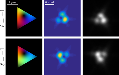
In both examples, the vortex is centered on a high-symmetry point of the aperture, which makes that the symmetry of the aperture is retained in all diffraction patterns. This makes that the two-fold rotational relation between the opposite vortex diffraction patterns, is equivalent with a mirror operation or a rotation over and rad for the five-fold and three-fold symmetric aperture respectively. To show that the two-fold rotation is independent from the symmetry of the beam position and symmetry of the aperture, in fig. 3, we shift the vortex beam to a non symmetric position on the triangular aperture, thereby destroying the three-fold symmetry. However, the two-fold rotation relation between diffraction patterns of the opposite vortex beams, remains present as expected.
IV Discussion
The EFL in eq. 11 shows that diffraction patterns of oppositely charged vortices always are two-fold symmetric with respect to each other when scattered on a real two-dimensional projected potential or two-dimensional apertures with real transmittance functions. The triangular aperture we used, fig. (2) already was suggested to determine the topological charge of a vortex beam by Hickmann et al. Hickmann2010 . By looking at the diffraction pattern, they were able to derive a rule for determining the magnitude of OAM of the incoming beam and they noted that diffraction patterns of opposite charge always were rotated by rad. Similarly, the pinhole aperture was proposed by Berkhout et al. Berkhout2008 as an alternative method to measure the topological charge of vortex beams. They also mention that, in the case of an odd number of holes, the diffraction pattern of opposite charge are mirrored to one another. Several other diffraction experiments with vortices were performed Sztul2006 ; Guo2009 ; Mazilu2012 ; Ghai2009 ; Shi2012 ; Liu2013a ; Ferreira2011 and, when a comparison with oppositely charged vortices was made, the same centrosymmetry between diffraction patterns always was observed.
In all these examples, however, the arguments to explain the symmetry between two opposite vortex beam diffraction patterns, relied on the symmetry of the specific apertures with respect to the center of the vortex (the studies on asymmetric apertures we found, unfortunately, do not compare opposite vortex beam diffraction patterns). The EFL, however, shows that this symmetry is a fundamental property of vortex beams scattered on any real, projected potential or two-dimensional apertures with real transmittance functions, independent from the symmetry of the scattering object.
Like Friedel’s law, EFL is useful when studying crystallography with vortex beams. In previous work, for example, we proposed the use of electron vortex beam diffraction to determine the handedness of chiral crystals Juchtmans2015 , crystals that only differ by a mirror operation, starting from the idea that vortex beams themselves are chiral. However, by extending Friedel’s law to vortex beams, it immediately becomes clear that the chirality can-not be learned directly from the projected potential of the crystal or the zeroth order Laue zone (ZOLZ) in the diffraction pattern, within the kinematical approximation. Any chiral effect that would be seen with one vortex, would only differ by a rotation of rad, with the opposite vortex. Therefor the left-handed crystal would show the same ZOLZ as its right-handed mirror image when rotated rad along the beam’s propagation direction. Looking at kinematically scattered electrons, any chiral effect must thus be searched for in the higher order Laue zones that contain three dimensional information about the crystal111In this case, it is easy to show that the HOLZ of a vortex beam is rotated rad with respect to the vortex, when, at the same time, the potential is mirrored along the plane perpendicular to the propagation of the vortex beam..
V Conclusion
In this work, we derived an extension of Friedel’s law (EFL) that applies to vortex beams, whether it concerns an optical, electron or any other particle beam. We show that when a vortex beam is diffracted on a two-dimensional scattering object, such as apertures, two diffraction patterns of vortex beams with opposite topological charge, always are rotated rad with respect to each other. This is independent from the symmetry of the scattering object and a fundamental property of vortex beam scattering. Our findings also apply for diffraction on a crystal, when kinematical scattering between the zeroth order Laue zone is considered. In general, this can be applied to X-ray, but not for electron diffraction on crystals, which is mostly dominated by dynamical scattering.
We verified our analytical derivation with numerical simulations and showed experimental results for electron vortex beams scattered on a multi-pinhole and triangular aperture. We compared our findings with observations made in literature, where this effect mostly is explained using the symmetry of the scattering objects with respect to the center of the vortex beam. However, with our derivation and by looking at vortex beams scattering on non-symmetric points of our apertures, we’ve shown that this symmetry is a more fundamental property of vortex beam diffraction. The work presented here provides deeper understanding in vortex beam diffraction, which in turn can be used to design new experiments to measure the topological charge of vortex beams with diffraction gratings, or study general vortex beam diffraction.
VI acknowledgments
The authors acknowledge support from the FWO (Aspirant Fonds Wetenschappelijk Onderzoek - Vlaanderen) and the EU under the Seventh Framework Program (FP7) under a contract for an Integrated Infrastructure Initiative, Reference No. 312483-ESTEEM2 and ERC Starting Grant 278510 VORTEX.
References
-
(1)
M. G. Friedel,
Sur
les symétries cristallines que peut réveiler la diffraction des
rayons Rontgen, Compte-rendus de l’Académie des Sciences 157 (1913)
1533.
URL http://visualiseur.bnf.fr/CadresFenetre?O=NUMM-3110{&}I=1533{&}M=tdm -
(2)
J. F. Nye, M. V. Berry,
Dislocations
in Wave Trains, Proceedings of the Royal Society A: Mathematical, Physical
and Engineering Sciences 336 (1605) (1974) 165–190.
doi:10.1098/rspa.1974.0012.
URL http://rspa.royalsocietypublishing.org/content/336/1605/165.abstract -
(3)
L. Allen, M. Padgett, M. Babiker, The
Orbital Angular Momentum Of Light 39 (1999) 291–372.
doi:10.1016/S0079-6638(08)70391-3.
URL http://eprints.gla.ac.uk/55287/ -
(4)
K. Y. Bliokh, Y. P. Bliokh, S. Savel’ev, F. Nori,
Semiclassical
Dynamics of Electron Wave Packet States with Phase Vortices, Physical
Review Letters 99 (19) (2007) 1–4.
doi:10.1103/PhysRevLett.99.190404.
URL http://link.aps.org/doi/10.1103/PhysRevLett.99.190404 -
(5)
C. W. Clark, R. Barankov, M. G. Huber, M. Arif, D. G. Cory, D. A. Pushin,
Controlling neutron orbital
angular momentum., Nature 525 (7570) (2015) 504–6.
doi:10.1038/nature15265.
URL http://dx.doi.org/10.1038/nature15265 -
(6)
V. Y. Bazhenov, M. V. Vasnetsov, M. S. Soskin,
Laser beams with
screw dislocations in their wavefronts, Jetp Lett 52 (1990) 429–431.
URL http://195.178.214.34/ps/1159/article{_}17529.pdf -
(7)
Z.-P. Luo, Y.-L. Sun, K.-N. An,
An
optical spin micromotor, Appl. Phys. Lett. 76 (13) (2000) 1779–1781.
URL http://scitation.aip.org/content/aip/journal/apl/76/13/10.1063/1.126165 -
(8)
H. He, M. E. J. Friese, N. R. Heckenberg, H. Rubinsztein-Dunlop,
Direct Observation
of Transfer of Angular Momentum to Absorptive Particles from a Laser Beam
with a Phase Singularity, Phys. Rev. Lett. 75 (5) (1995) 826–829.
doi:10.1103/PhysRevLett.75.826.
URL http://link.aps.org/doi/10.1103/PhysRevLett.75.826 -
(9)
M. E. J. Friese, H. Rubinsztein-Dunlop, J. Gold, P. Hagberg, D. Hanstorp,
Optically
driven micromachine elements, Applied Physics Letters 78 (4) (2001)
547–549.
doi:10.1063/1.1339995.
URL http://scitation.aip.org/content/aip/journal/apl/78/4/10.1063/1.1339995 -
(10)
G. Foo, D. M. Palacios, G. a. Swartzlander,
Optical vortex
coronagraph., Optics letters 30 (24) (2005) 3308–10.
URL http://www.ncbi.nlm.nih.gov/pubmed/18607427 -
(11)
G. Swartzlander, R. Hernandez-Aranda,
Optical Rankine
Vortex and Anomalous Circulation of Light, Physical Review Letters 99 (16)
(2007) 163901.
doi:10.1103/PhysRevLett.99.163901.
URL http://link.aps.org/doi/10.1103/PhysRevLett.99.163901 -
(12)
E. Serabyn, D. Mawet, R. Burruss,
An image of an exoplanet
separated by two diffraction beamwidths from a star., Nature 464 (7291)
(2010) 1018–20.
doi:10.1038/nature09007.
URL http://www.ncbi.nlm.nih.gov/pubmed/20393557 -
(13)
G. C. G. Berkhout, M. W. Beijersbergen,
Method for
Probing the Orbital Angular Momentum of Optical Vortices in Electromagnetic
Waves from Astronomical Objects, Physical Review Letters 101 (10) (2008)
100801.
doi:10.1103/PhysRevLett.101.100801.
URL http://link.aps.org/doi/10.1103/PhysRevLett.101.100801 -
(14)
D. L. Andrews (Ed.),
Structured Light and Its
Applications: An Introduction to Phase-Structured Beams and Nanoscale Optical
Forces, Elsevier Science, 2011.
URL http://books.google.be/books?id=BNdCkCXOXX4C -
(15)
J. Wang, J.-Y. Yang, I. M. Fazal, N. Ahmed, Y. Yan, H. Huang, Y. Ren, Y. Yue,
S. Dolinar, M. Tur, A. E. Willner,
Terabit
free-space data transmission employing orbital angular momentum
multiplexing, Nature Phot. 6 (2012) 488–496.
URL http://www.nature.com/nphoton/journal/v6/n7/full/nphoton.2012.138.html -
(16)
S. Roychowdhury, V. K. Jaiswal, R. Singh,
Implementing
controlled NOT gate with optical vortex, Optics Communications 236 (4-6)
(2004) 419–424.
doi:10.1016/j.optcom.2004.03.036.
URL http://linkinghub.elsevier.com/retrieve/pii/S0030401804003013 -
(17)
M. Uchida, A. Tonomura,
Generation of electron
beams carrying orbital angular momentum., Nature 464 (7289) (2010)
737–739.
doi:10.1038/nature08904.
URL http://www.ncbi.nlm.nih.gov/pubmed/20360737 -
(18)
J. Verbeeck, H. Tian, P. Schattschneider,
Production and
application of electron vortex beams., Nature 467 (7313) (2010) 301–4.
doi:10.1038/nature09366.
URL http://www.ncbi.nlm.nih.gov/pubmed/20844532 -
(19)
L. Clark, a. Béché, G. Guzzinati, a. Lubk, M. Mazilu, R. Van
Boxem, J. Verbeeck,
Exploiting
Lens Aberrations to Create Electron-Vortex Beams, Physical Review Letters
111 (6) (2013) 064801.
doi:10.1103/PhysRevLett.111.064801.
URL http://link.aps.org/doi/10.1103/PhysRevLett.111.064801 -
(20)
A. Béché, R. Van Boxem, G. Van Tendeloo, J. Verbeeck,
Magnetic monopole
field exposed by electrons, Nature Physics 10 (1) (2013) 26–29.
doi:10.1038/nphys2816.
URL http://www.nature.com/doifinder/10.1038/nphys2816 -
(21)
R. Juchtmans, L. Clark, A. Lubk, J. Verbeeck,
Spiral phase plate
contrast in optical and electron microscopy, Phys. Rev. A 94 (2016) 023838.
arXiv:1605.07847,
doi:10.1103/PhysRevA.94.023838.
URL http://dx.doi.org/10.1103/PhysRevA.94.023838 -
(22)
J. Verbeeck, H. Tian, G. Van Tendeloo,
How to Manipulate Nanoparticles
with an Electron Beam?, Advanced Materials 25 (8) (2013) 1114–1117.
doi:10.1002/adma.201204206.
URL http://www.ncbi.nlm.nih.gov/pubmed/23184603http://doi.wiley.com/10.1002/adma.201204206 -
(23)
E. Karimi, L. Marrucci, V. Grillo, E. Santamato,
Spin-to-Orbital
Angular Momentum Conversion and Spin-Polarization Filtering in Electron
Beams, Physical Review Letters 108 (4) (2012) 044801.
doi:10.1103/PhysRevLett.108.044801.
URL http://link.aps.org/doi/10.1103/PhysRevLett.108.044801 -
(24)
R. Juchtmans, A. Béché, A. Abakumov, M. Batuk, J. Verbeeck,
Using electron
vortex beams to determine chirality of crystals in transmission electron
microscopy, Phys. Rev. B 91 (9) (2015) 94112.
doi:10.1103/PhysRevB.91.094112.
URL http://link.aps.org/doi/10.1103/PhysRevB.91.094112 -
(25)
R. Juchtmans, J. Verbeeck,
Orbital angular
momentum in electron diffraction and its use to determine chiral crystal
symmetries, Physical Review B 92 (13) (2015) 134108.
doi:10.1103/PhysRevB.92.134108.
URL http://link.aps.org/doi/10.1103/PhysRevB.92.134108 -
(26)
R. Juchtmans, J. Verbeeck,
Local orbital angular momentum revealed by
spiral phase plate imaging in transmission electron microscopy, Phys. Rev.
A 93 (2016) 023811.
arXiv:1512.04789,
doi:10.1103/PhysRevA.93.023811.
URL http://journals.aps.org/pra/abstract/10.1103/PhysRevA.93.023811http://arxiv.org/abs/1512.04789 - (27) J. Hickmann, E. Fonseca, W. Soares, S. Chávez-Cerda, Unveiling a Truncated Optical Lattice Associated with a Triangular Aperture Using Light’s Orbital Angular Momentum, Physical Review Letters 105 (5) (2010) 53904. doi:10.1103/PhysRevLett.105.053904.
-
(28)
G. Guzzinati, L. Clark, A. Béché, J. Verbeeck,
Measuring
the orbital angular momentum of electron beams, Physical Review A 89 (2)
(2014) 025803.
arXiv:1401.7211,
doi:10.1103/PhysRevA.89.025803.
URL http://arxiv.org/abs/1401.7211{%}5Cnhttp://link.aps.org/doi/10.1103/PhysRevA.89.025803 -
(29)
C.-S. Guo, S.-J. Yue, G.-X. Wei,
Measuring the
orbital angular momentum of optical vortices using a multipinhole plate,
Applied Physics Letters 94 (23) (2009) 231104.
doi:10.1063/1.3151920.
URL http://scitation.aip.org/content/aip/journal/apl/94/23/10.1063/1.3151920http://link.aip.org/link/APPLAB/v94/i23/p231104/s1{&}Agg=doi - (30) L. Shi, L. Tian, X. Chen, Characterizing topological charge of optical vortex using non-uniformly distributed multi-pinhole plate, Chinese Optics Letters 10 (12) (2012) 120501–120503. doi:10.3788/COL201210.120501.A.
-
(31)
L. Clark, A. Béché, G. Guzzinati, J. Verbeeck,
Quantitative
measurement of orbital angular momentum in electron microscopy, Physical
Review A 89 (5) (2014) 053818.
arXiv:1403.4398,
doi:10.1103/PhysRevA.89.053818.
URL http://link.aps.org/doi/10.1103/PhysRevA.89.053818{%}5Cnhttp://arxiv.org/abs/1403.4398 - (32) M. De Graef, Introduction to Conventional Transmissino Electron Microscopy, Cambridge University Press, 2003.
- (33) M. Born, E. Wolf, Principles of Optics: Electromagnetic Theory of Propagation, Interference and Diffraction of Light, 7th Edition, Cambridge University Press, 1999.
-
(34)
Z. Bouchal, R. Elechovsky, V. Kollarov,
Nondiffracting
and vortex beams generated by spatial light modulator, Proceedings of SPIE
5945 (2005) 59450F–59450F–6.
doi:10.1117/12.638909.
URL http://link.aip.org/link/PSISDG/v5945/i1/p59450F/s1{&}Agg=doi - (35) H. I. Sztul, R. R. Alfano, Double-slit interference with Laguerre-Gaussian beams., Optics letters 31 (7) (2006) 999–1001. doi:10.1364/OL.31.000999.
- (36) M. Mazilu, A. Mourka, T. Vettenburg, E. M. Wright, K. Dholakia, Simultaneous determination of the constituent azimuthal and radial mode indices for light fields possessing orbital angular momentum, Applied Physics Letters 100 (23). doi:10.1063/1.4728111.
- (37) D. P. Ghai, P. Senthilkumaran, R. S. Sirohi, Single-slit diffraction of an optical beam with phase singularity, Optics and Lasers in Engineering 47 (1) (2009) 123–126. doi:10.1016/j.optlaseng.2008.07.019.
-
(38)
R. Liu, J. Long, F. Wang, Y. Wang,
Characterizing
the phase profile of a vortex beam with angular-double-slit interference,
Journal of Optics 15 (1) (2013) 125712.
arXiv:arXiv:1305.5631v1, doi:10.1088/2040-8978/15/12/125712.
URL http://stacks.iop.org/2040-8986/15/i=12/a=125712?key=crossref.c549395bb4a701a5bfd083c0ddd42ad7{%}5Cnhttp://iopscience.iop.org/2040-8986/15/12/125712 - (39) Q. S. Ferreira, A. J. Jesus-Silva, E. J. S. Fonseca, J. M. Hickmann, Fraunhofer diffraction of light with orbital angular momentum by a slit., Optics letters 36 (16) (2011) 3106–3108. doi:10.1364/OL.36.003106.
- (40) In this case, it is easy to show that the HOLZ of a vortex beam is rotated rad with respect to the vortex, when, at the same time, the potential is mirrored along the plane perpendicular to the propagation of the vortex beam.