Study of Parametric Instability of gravitational wave detectors using silicon test masses
Abstract
Parametric instability is an intrinsic risk in high power laser interferometer gravitational wave detectors, in which the optical cavity modes interact with the acoustic modes of the mirrors leading to exponential growth of the acoustic vibration. In this paper, we investigate the potential parametric instability for a proposed next generation gravitational wave detector based on cooled silicon test masses. It is shown that there would be about 2 unstable modes per test mass, with the highest parametric gain of . The importance of developing suitable instability suppression schemes is emphasized.
-
09/09/2016
1 Introduction
Gravitational waves, predicted by Einstein a century ago, have finally been directly detected [1] in 2015, enabling us to have a first glimpse of two black holes merging. The detections [1] [2] gravitational waves open the new windows on the universe and there are now strong reasons for improving detector sensitivity. At their design sensitivity, the kilometer scale interferometer detectors such as Advanced LIGO detectors [3] and Virgo detector [4] are expected to be able to detect gravitational waves events per year [5]. This data will be a critical resource for understanding the origin and distribution of stellar mass black holes in the universe.
To reach high sensitivity, advanced laser interferometer detectors must use very high laser power inside the optical cavities to reduce quantum noise. Braginsky pointed out [6] in the early 2000s that with extremely high laser power in the interferometer cavity, radiation pressure coupling between the acoustic modes and cavity optical modes can cause 3-mode parametric instability (PI), resulting in the exponential growth of many acoustic mode amplitudes and disruption of the operation of the interferometer. Zhao et al.[7] undertook a detailed 3D study of PI in a detector similar to the advanced LIGO design. The modeling considered interactions in individual arm cavities, and made predictions [7] that were in relatively close agreement to recent observations of PI on the Advanced LIGO detectors [8]. Zhao′s paper discussed the use of small variations of the mirror radius of curvature to tune the system to a local minimum of parametric gain. In fused silica the thermal distortion of test masses is used for this purpose. Subsequent detailed modeling [9] showed that interactions between arm cavities, power recycling and signal recycling cavities could significantly modify the predictions, and further work identified many methods of suppressing PI, such as electrostatic feedback, optical feedback and the use of passive dampers [10, 11, 12, 13, 14, 15, 16, 17]. Unfortunately the conditions that enable high sensitivity appear to always coincide with the conditions that enable PI. To date, no method has been demonstrated that can completely eliminate parametric instability. As advanced LIGO power is increased, it is anticipated that a combination of of thermal tuning, electrostatic feedback and passive dampers will be able to eliminate all instabilities.
To increase the sensitivity of detectors beyond that achievable with the current advance LIGO detectors, various options are being investigated. Much effort is underway to design the next generation of detectors. Proposed designs include the Einstein Telescope (ET) [18] , several LIGO upgrades designs such as LIGO A+, LIGO Voyager [19], a 40km interferometer [20] and an 8km interferometer[21]. All the future designs required the use of high laser power to overcome quantum shot noise for high frequency sensitivity. It is apparent that each of these designs will need to consider the PI problem. In 2012, Strigin studied the PI problem of the 10km Fabry-Parrot cavity in ET design with sapphire or silicon test masses [22]. His result suggested that there would be unstable modes in such systems.
Parametric instability arises through the coincidental matching of test mass acoustic mode frequencies and mode shapes with optical cavity transverse modes for which the frequency difference from the main TEM00 pump laser mode is in the 1 - 100kHz range. Detailed predictions must take into account the details of the test mass shapes and optical cavity design. However in general, the risk of modal coincidences depends on the optical modes density and the acoustic mode density. The optical mode density depends on the cavity free spectral range, determined by the cavity length, and the transverse mode spacing called the mode gap, which is proportional to the inverse cosine of the cavity g-factor. The acoustic mode density depends on test mass sizes and inversely on the sound velocity. The particular design analyzed here replaces the 40kg fused silica test masses of Advanced LIGO with 200kg cooled silicon test masses. The high sound velocity and low acoustic loss of silicon could enable significant suppression of thermal noise which can be further improved through use of crystalline optical coatings[23]. The high sound velocity of silicon acts to reduce modal coincidences that lead to PI, but the increased mass acts in the other direction.
This paper investigates this issue in detail for the specific design called the LIGO voyager blue design. While the results are specific to this design, they give an indication of the problems that could be faced by many future generation gravitational wave detectors. For this analysis we use a single cavity model for PI modeling because of its general agreement with observations. Any more complex models depend on details of the power and signal recycling cavities, and do not change the general pattern of instability. Hence this model provides a good indication of the level of the PI.
2 Parametric instability
2.1 Parametric instability
The 3-mode parametric interaction involves 2 optical modes (the carrier fundamental mode and the higher order optical mode ) and an acoustic mode. If the transverse modes and acoustic modes have a similar spatial distribution and appropriate frequency relations, three mode interactions can be strong. The frequency match between carrier mode , transverse mode and acoustic mode is represented by the three-mode detuning parameter
| (1) |
When , where is the line-width of transverse mode, strong interaction will occur.
The parametric gain is used to describe the three-mode interaction in the cavity. can be described as follows in the case of single optical cavity:
| (2) |
where is the circulating power in the cavity arm, is the overlapping factor, is the quality factor of the acoustic mode, is the quality factor of the optical mode, is the mass of the test mass, is the velocity of light, is the length of the cavity, is the frequency of acoustic mode, is the frequency detuning parameter of Eq. 1, describing either excitation or damping of the acoustic modes, is the half line-width of the optical mode.
In the Stokes process (), the optical energy is transferred to acoustic mode, exciting the acoustic mode. For , the exciting force exceeds damping force, the acoustic mode amplitude will rise exponentially leading to instability; , the amplitude will be amplified by a factor and the system will remain stable. In the Anti-Stokes process (), , the acoustic mode transfer energy to the optical mode, and the acoustic mode is cold damped. Stocks and anti-stocks processes could all happen in an optical cavity, but due to the asymmetrical structure of the Stokes and anti-Stokes process, they cannot be canceled out[6]. Moreover, multiple optical modes can interact with one acoustic mode simultaneously [24], which is reflected by the summation of Eq. 2.
From eq. 2, it can be seen that depends on frequency match between the acoustic mode frequency and the cavity mode frequency , as well as the overlap between the acoustic modes and the optical cavity mode. These will be addressed below in detail for a particular interferometer design.
2.2 LIGO Voyager design
The Voyager conceptual design is proposed as a major upgrade of Advanced LIGO. It was first proposed in 2012 and improved based on simulations and experiments. Subsequent studies of Voyager led to 3 ”straw-man” designs, known as Red, Green and Blue. Here the Blue design is used for our simulation. The blue design makes feature of [25]:
-
(1)
laser wavelength of 2000 nm
-
(2)
Large cryogenic Silicon mirror: 204 kg Silicon mirrors at the operating temperature of 123 K are considered.
-
(3)
Silicon cryogenic suspension: Silicon ribbons (and perhaps blade springs) in the final stage suspension at 123 K are employed.
-
(4)
Newtonian noise: Newtonian noise is subtracted by a factor of 30 with seismometer arrays.
-
(5)
High power 2000 nm laser: 2000 nm wavelength lasers operating at W are employed. Arm cavity powers will reach MW
-
(6)
Coating Thermal Noise: The beam spot size is kept at the aLIGO size level to avoid optical degeneracy issues and epitaxial coatings on the test masses are employed for a mirror thermal noise improvement of 3 to 10.
-
(7)
Quantum noise: Squeezed light injection (10 dB) and a 300 m filter cavity for frequency dependent squeeze angle is assumed.
The parameters used for calculating parametric gain for the Voyager Blue design are listed in Table 1.
| Parameter | Advanced LIGO | Voyager Blue |
|---|---|---|
| Mirror substrate | fused silica | silicon |
| Young’s modulus | 73 GPa | 189 GPa |
| Poisson ratio | 0.167 | 0.181 |
| Density | 2220 | 2332 |
| Mirror radius | 0.17m | 0.225m |
| Mirror thickness | 0.20m | 0.55m |
| Beam radius on ITM/ETM | 0.053m/0.062m | 0.059m/0.084m |
| Mirror mass | 40kg | 204kg |
| Final Stage temperature | 300k | 123k |
| Transimissitivity of ITM | ||
| Acoustic mode quality factor | ||
| radius of curvature of ITM/ETM | 1934m/2245m | 1801m/2596m |
| Cavity length | 3994.5m | 4000m |
| Finesse | 450 | 450 |
| wavelength | 1064nm | 2000nm |
| Circulating Power | 830 kW | 3 MW |
2.3 Test mass acoustic modes
We used the finite element analysis software COMSOL to simulate the acoustic modes of the test mass using the properties shown in table 1, from 5kHz up to kHz, in total 2194 acoustic modes. Compared with aLIGO test mass, the mode density is of comparable magnitude.
For the Voyager blue design, it is proposed [25] to have black coating on the test mass barrel for radiative cooling. It is clear that the lossy black coating on the barrel will reduce the Q-factor of acoustic modes and increase the thermal noise [13], depending on their strain energy distribution on the barrel. We assume the acoustic mode Q-factors are reduced by an order of magnitude from the silicon intrinsic Q factor of to due to the combined effects of both black coating on the barrel and the optical coating on the surfaces.
2.4 Optical cavity modes
The frequencies and shapes of high order modes also need to be determined to calculate the overlap with certain acoustic modes. The higher order Hermite-Gaussian mode with transverse mode number (n,m) and longitude number k can be written as
| (3) |
where
| (4) |
are the Hermite polynomials of order n, and
| (5) |
In a Fabry-Perot cavity, the resonant frequency of higher-order modes are given as:
| (6) |
The frequency spacing between the (n,m) transverse mode and the 00 mode is
| (7) |
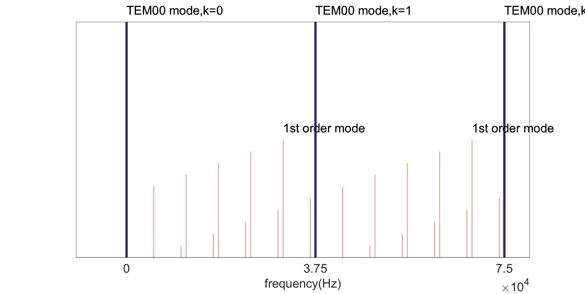
Figure 1 shows a schematic diagram of mode structure of a cavity, up to order optical mode. Table 2 lists the mode gaps (frequency difference) between carrier mode and the Stokes/Anti-Stokes modes considered in this simulation.
| optical mode order | ||
| k=0 | ||
| 6 | 1 | 73 |
| 7 | 7 | 67 |
| 8 | 13 | 61 |
| 9 | 20 | 54 |
| 10 | 26 | 48 |
| k=1 | ||
| 1 | 6 | 68 |
| 2 | 12 | 62 |
| 3 | 19 | 55 |
| 4 | 25 | 49 |
| 5 | 32 | 42 |
| 6 | 38 | 36 |
| 7 | 44 | 30 |
| 8 | 51 | 23 |
| 9 | 57 | 17 |
| 10 | 64 | 10 |
| k=2 | ||
| 1 | 43 | 31 |
| 2 | 50 | 24 |
| 3 | 56 | 18 |
| 4 | 63 | 11 |
| 5 | 69 | 5 |
The strength of the scattering interaction is governed by a three-mode detuning parameter (Eq. 1) and the ratio of . The half line-width (also called the relaxation rate) of the transverse mode is defined as
| (8) |
where is the finesse of the cavity, which is the same as Advanced LIGO. Narrower linewidths represent smaller cavity loss and higher Q-factor. For laser freuency , the quality factor is defined as:
| (9) |
2.5 Overlap
The overlapping factor is given as
| (10) |
where is the volume of test mass. Mathematically, the spatial match between the carrier mode , transverse mode , and the acoustic mode is defined by the integral , where is the displacement vector of the acoustic mode normal to the test mass surface. The larger value of the integral, the better overlap is between the three modes. The integral represents the effective volume of the acoustic mode.
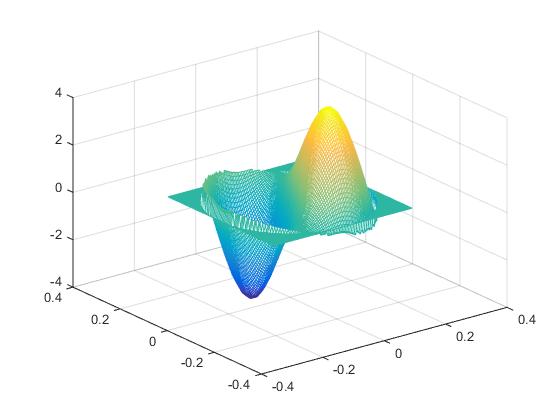
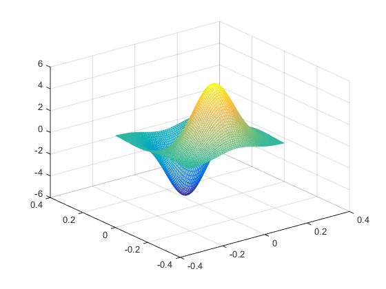
Figure 2 shows an example of the shape of one of the acoustic mode and an optical 01 mode, which are very similar and for which the overlap will be high. .
In our analysis, we considered the worst case scenario by rotating the displacement of each acoustic mode every from 0 to to locate the best match orientation with the optical modes to obtain the maximal overlapping parameter . The overlap of each acoustic mode to all the 21 optical modes up to order considered here are calculated.
2.6 Parametric Gain
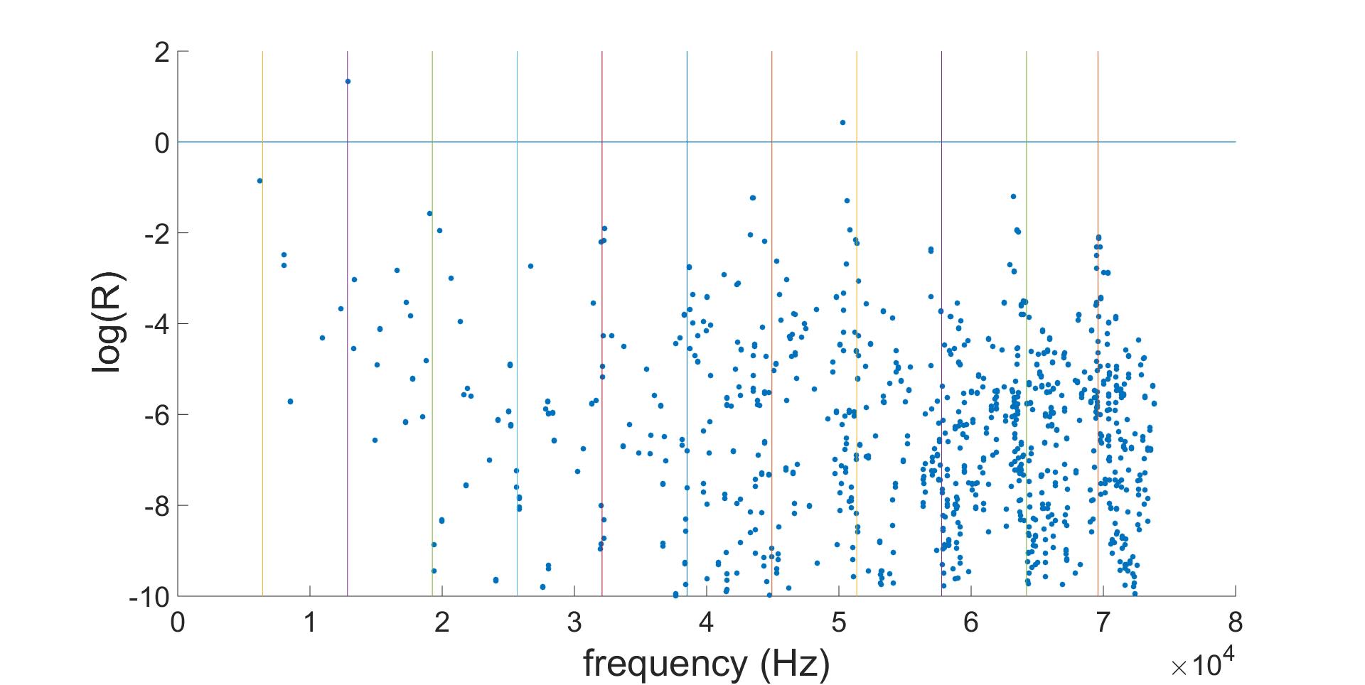
Using the results of section 2.3, 2.4 and 2.5, we calculated the parametric gain for acoustic modes up to 74 kHz and up to order optical modes. Results is plot in Fig. 3. It can be seen that, at cavity power of 3MW, there are 1161 modes with , of which 2 modes have , 4 modes with , and 121 modes with . The maximum gain is 76.
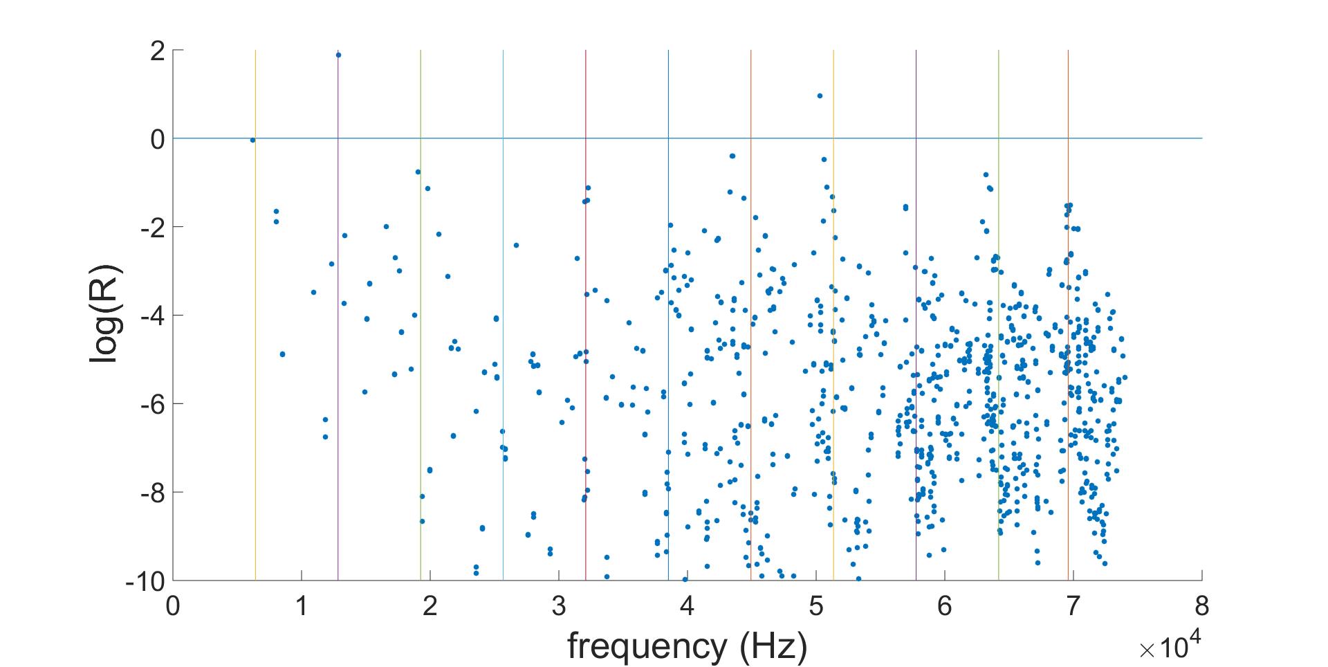
It can also be seen from Fig. 3 that the frequency condition plays a big role in the parametric gain. Those acoustic modes having the frequencies near the mode gaps between the and modes have higher parametric gain.
Thermal tuning of the RoC of the cavity (and thus changing the mode gaps of the optical cavity) was proposed [7] to suppress parametric instability. However, due to the high acoustic mode density, changing the cavity mode gaps to suppress one acoustic mode instability may result in increasing other acoustic modes parametric gain.
For cryogenic detectors, tuning of the RoC thermally may not be effective. However, since there appears fewer unstable modes then in aLIGO, it would be relatively easy to use other methods such as electrostatic feedback or passive damper to suppress PI.
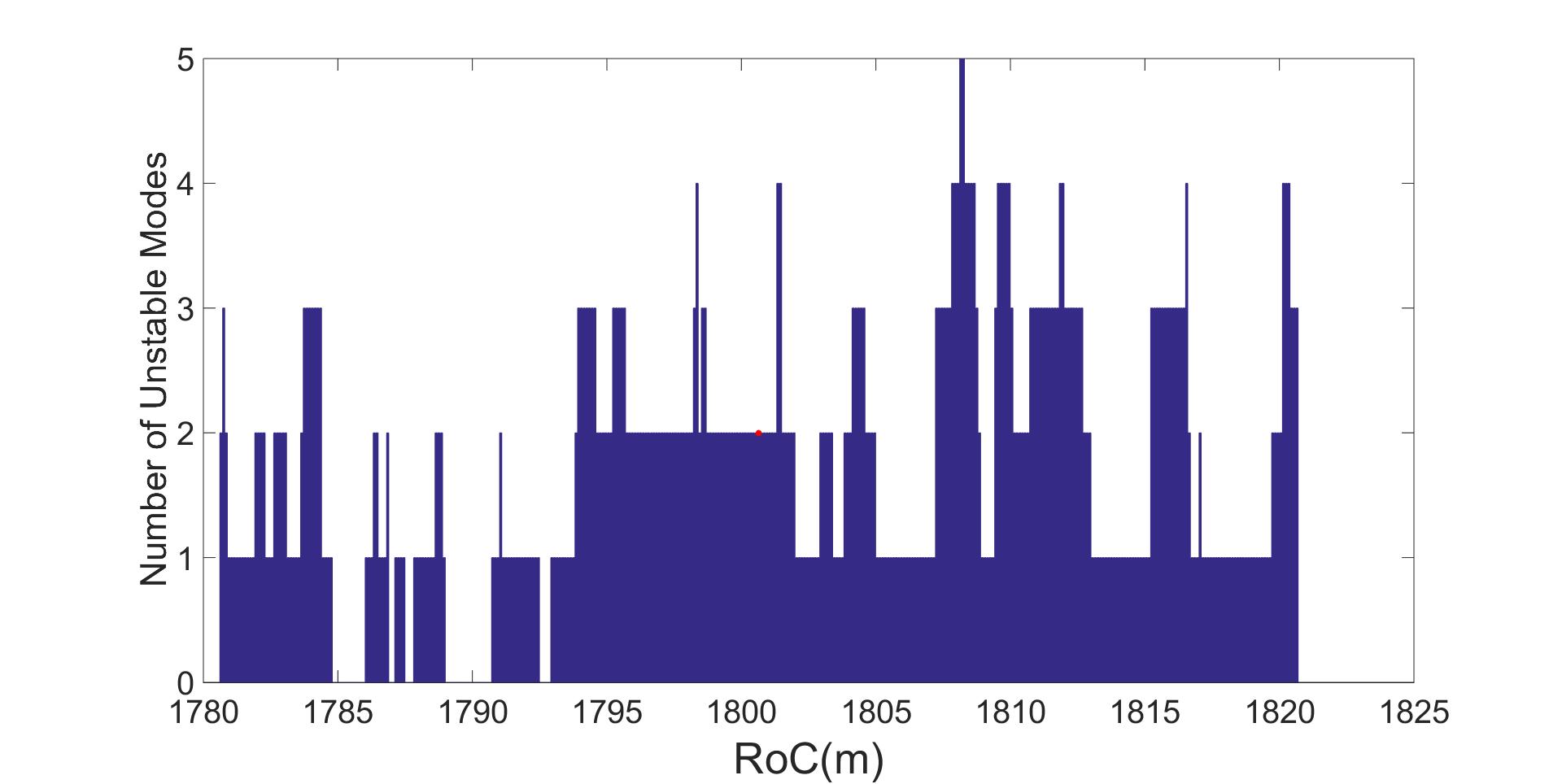
It would be interesting to see if we could design the mirror RoC, so that there can be fewer acoustic modes with . Fig. 4 and Fig. 5 shows the maximum parametric gain and the number of unstable modes as a function of the RoC of the ITM.
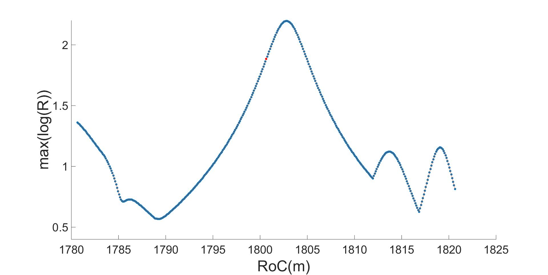
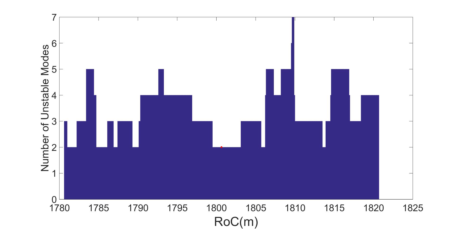
It can be seen that although there is nowhere that the parametric gain would be all below unity, there would be some ”sweet regions” where both the number of the unstable modes and the maximum parametric gain are smaller. For example, at RoC 1790m, there would be less than 3 unstable modes with maximum R less than 4. Even with the uncertainties in finite element modeling for acoustic mode frequencies (usually a few hundred to kHz different from measured values) [26], Figs 4 and 5 provide useful information for choosing the favorable RoC of the test masses in regards to parametric instabilities. Besides, Fig 4 shows that the maximum R comes from the same acoustic mode in the middle part ( RoC ) and then changes to another acoustic mode. The dominating acoustic mode is found out to be 12880 Hz interacting with second order optical mode. If we could damp this acoustic mode, the maximum parametric gain would be reduced dramatically.
For silicon test masses, the optical absorption of large samples is still uncertain. It may be possible to avoid high absorbed power in the input test mass and beam splitter by using reduced circulating power in the power recycling cavity, compensated for by using higher arm cavity finesse to maintain the same arm cavity circulating power (i.e. 3 MW). Here we have chosen a finesse of 3000 for the simulation to investigate any difference of parametric instability with this high cavity finesse. The results are shown in Figs. 6, 7 and 8.
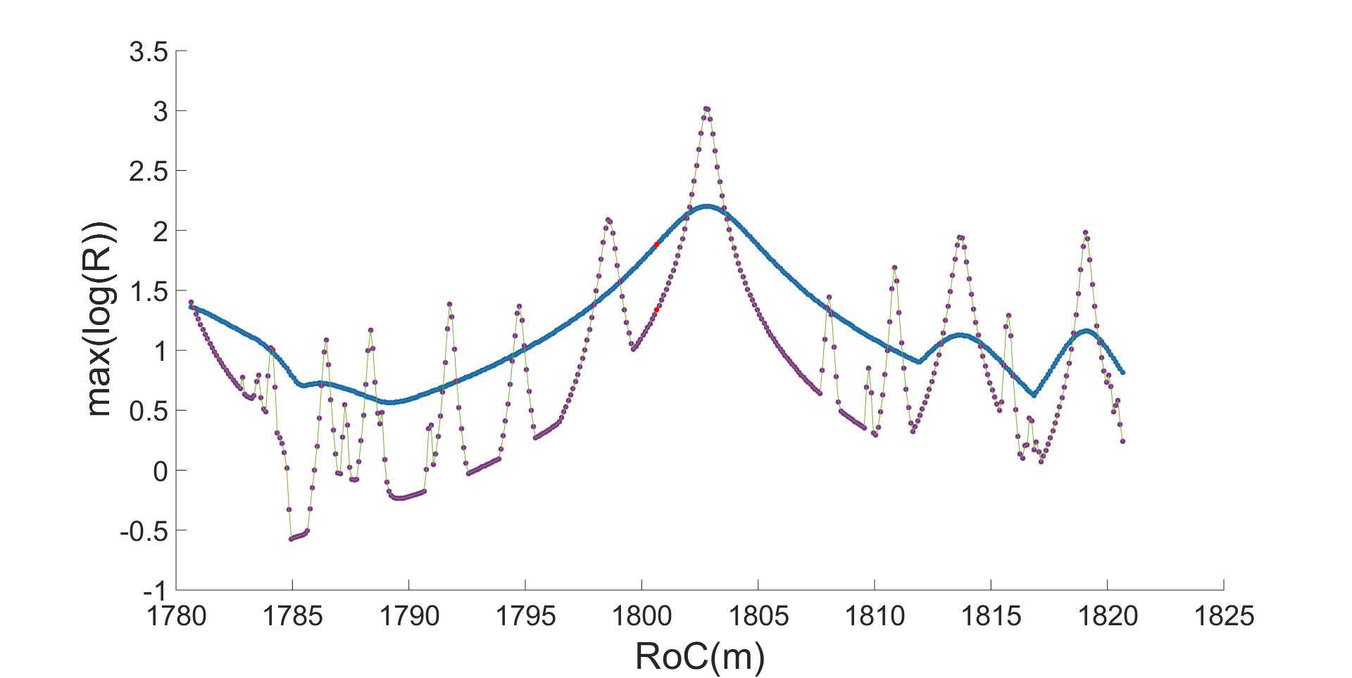
It can be seen that for the particular RoCs in Table 1, the unstable modes for the high finesse case is the same as the lower finesse case, with a smaller maximum gain . From Figs. 7 and 8, it is clear that due to the higher Q-factor and narrower linewidths of optical modes for high finesse cavity, the worst parametric gain is much higher than that of lower finesse, but with fewer unstable modes. It can also be seen that for the high finesse case, there would be several windows without instability, such as those near RoC m, RoC m. Moreover, there are more windows with only one unstable mode which will be easier to suppress.
3 Conclusion
The result presented here is the first step in analyzing the parametric instability in the laser interferometer gravitational wave detector with silicon test masses. The single cavity model was used for simplicity. In practical configurations, the power and signal recycling cavities will change the parametric gain depending on the resonance condition of the high order mode involved inside the recycling cavities. As reference[9] pointed out that any unstable modes present in the single cavity will be potential threats in a full interferometer. The first detailed analysis of parametric instability of Advanced LIGO[7] using a single cavity model predicted that there would be 7 unstable acoustic modes per each fused silica test mass, with parametric gain up to 7, at circulating power of 800 kW. This means about a total of 28 unstable modes in 4 test masses of the two cavity arms. So far Advanced LIGO observed total 10 unstable modes, with the maximum parametric gain of the order of 10, operating at of designed power. This is consistent with the the single cavity simulation. A more complicated simulation [9] that took into consideration the recycling cavities and losses gave deeper insight of the parametric instability of the real system. However, The simpler single cavity simulation is a very good indicator about the potential parametric instability problem of future design.
Assuming a Q-factor of for the acoustic modes of the test mass, we estimated that there would be unstable modes with maximum parametric gain of 76 for the Voyager blue design. This means that the potential parametric instability risk is roughly at the same level as the advanced LIGO detectors, at a much higher optical power level. The choice of a high sound velocity test mass material is advantageous in regards to parametric instabilities.
As designs are further developed, it will be necessary to consider all the effects mentioned above as well as details of test mass structures such as flats on the barrel for suspensions, and the diffraction losses of high order modes.
Acknowledgment
The authors would like to thank the support from LIGO scientific collaborations. We also like to thank many useful discussion with Dr. Jiayi Qin, Dr. Xu Chen and Carl Blair. This work is supported by Australian Research Council and is part of the Australian Consortium for Interferometric Gravitational wave Astronomy.
Reference
References
- [1] BP Abbott, Richard Abbott, TD Abbott, MR Abernathy, Fausto Acernese, Kendall Ackley, Carl Adams, Thomas Adams, Paolo Addesso, RX Adhikari, et al. Observation of gravitational waves from a binary black hole merger. Physical review letters, 116(6):061102, 2016.
- [2] BP Abbott, R Abbott, TD Abbott, MR Abernathy, F Acernese, K Ackley, C Adams, T Adams, P Addesso, RX Adhikari, et al. Gw151226: Observation of gravitational waves from a 22-solar-mass binary black hole coalescence. Physical Review Letters, 116(24):241103, 2016.
- [3] Junaid Aasi, BP Abbott, Richard Abbott, Thomas Abbott, MR Abernathy, Kendall Ackley, Carl Adams, Thomas Adams, Paolo Addesso, RX Adhikari, et al. Advanced ligo. Classical and Quantum Gravity, 32(7):074001, 2015.
- [4] T Accadia, F Acernese, M Alshourbagy, P Amico, F Antonucci, S Aoudia, N Arnaud, C Arnault, KG Arun, P Astone, et al. Virgo: a laser interferometer to detect gravitational waves. Journal of Instrumentation, 7(03):P03012, 2012.
- [5] Krzysztof Belczynski, Daniel E Holz, Tomasz Bulik, and Richard O’Shaughnessy. The first gravitational-wave source from the isolated evolution of two stars in the 40–100 solar mass range. Nature, 534(7608):512–515, 2016.
- [6] VB Braginsky, SE Strigin, and S Pr Vyatchanin. Parametric oscillatory instability in fabry–perot interferometer. Physics Letters A, 287(5):331–338, 2001.
- [7] C Zhao, L Ju, J Degallaix, S Gras, and DG Blair. Parametric instabilities and their control in advanced interferometer gravitational-wave detectors. Physical review letters, 94(12):121102, 2005.
- [8] Matthew Evans, Slawek Gras, Peter Fritschel, John Miller, Lisa Barsotti, Denis Martynov, Aidan Brooks, Dennis Coyne, Rich Abbott, Rana X. Adhikari, Koji Arai, Rolf Bork, Bill Kells, Jameson Rollins, Nicolas Smith-Lefebvre, Gabriele Vajente, Hiroaki Yamamoto, Carl Adams, Stuart Aston, Joseph Betzweiser, Valera Frolov, Adam Mullavey, Arnaud Pele, Janeen Romie, Michael Thomas, Keith Thorne, Sheila Dwyer, Kiwamu Izumi, Keita Kawabe, Daniel Sigg, Ryan Derosa, Anamaria Effler, Keiko Kokeyama, Stefan Ballmer, Thomas J. Massinger, Alexa Staley, Matthew Heinze, Chris Mueller, Hartmut Grote, Robert Ward, Eleanor King, David Blair, Li Ju, and Chunnong Zhao. Observation of parametric instability in advanced ligo. Phys. Rev. Lett., 114:161102, Apr 2015.
- [9] Slawomir Gras, Chunnong Zhao, DG Blair, and Li Ju. Parametric instabilities in advanced gravitational wave detectors. Classical and Quantum Gravity, 27(20):205019, 2010.
- [10] Jérôme Degallaix, Chunnong Zhao, Li Ju, and David Blair. Thermal tuning of optical cavities for parametric instability control. JOSA B, 24(6):1336–1343, 2007.
- [11] L Ju, DG Blair, C Zhao, S Gras, Z Zhang, P Barriga, H Miao, Y Fan, and L Merrill. Strategies for the control of parametric instability in advanced gravitational wave detectors. Classical and Quantum Gravity, 26(1):015002, 2008.
- [12] S Gras, DG Blair, and L Ju. Test mass ring dampers with minimum thermal noise. Physics Letters A, 372(9):1348–1356, 2008.
- [13] S Gras, DG Blair, and C Zhao. Suppression of parametric instabilities in future gravitational wave detectors using damping rings. Classical and Quantum Gravity, 26(13):135012, 2009.
- [14] YaoHui Fan, Lucienne Merrill, ChunNong Zhao, Li Ju, David Blair, Bram Slagmolen, David Hosken, Aidan Brooks, Peter Veitch, and Jesper Munch. Testing the suppression of opto-acoustic parametric interactions using optical feedback control. Classical and Quantum Gravity, 27(8):084028, 2010.
- [15] John Miller, Matthew Evans, Lisa Barsotti, Peter Fritschel, Myron MacInnis, Richard Mittleman, Brett Shapiro, Jonathan Soto, and Calum Torrie. Damping parametric instabilities in future gravitational wave detectors by means of electrostatic actuators. Physics Letters A, 375(3):788–794, 2011.
- [16] Chunnong Zhao, Li Ju, Qi Fang, Carl Blair, Jiayi Qin, David Blair, Jerome Degallaix, and Hiroaki Yamamoto. Parametric instability in long optical cavities and suppression by dynamic transverse mode frequency modulation. Physical Review D, 91(9):092001, 2015.
- [17] S. Gras, P. Fritschel, L. Barsotti, and M. Evans. Resonant dampers for parametric instabilities in gravitational wave detectors. Phys. Rev. D, 92:082001, Oct 2015.
- [18] M Punturo, M Abernathy, F Acernese, B Allen, Nils Andersson, K Arun, F Barone, B Barr, M Barsuglia, M Beker, et al. The einstein telescope: a third-generation gravitational wave observatory. Classical and Quantum Gravity, 27(19):194002, 2010.
- [19] LIGO Scientific Collaboration. Instrument Science White Paper. https://dcc.ligo.org/LIGO-T1400316/public, 2015.
- [20] Sheila Dwyer, Daniel Sigg, Stefan W Ballmer, Lisa Barsotti, Nergis Mavalvala, and Matthew Evans. Gravitational wave detector with cosmological reach. Physical Review D, 91(8):082001, 2015.
- [21] David Blair, Li Ju, ChunNong Zhao, LinQing Wen, HaiXing Miao, RongGen Cai, JiangRui Gao, XueChun Lin, Dong Liu, Ling-An Wu, et al. The next detectors for gravitational wave astronomy. Science China Physics, Mechanics & Astronomy, 58(12):1–34, 2015.
- [22] SE Strigin. The effect of parametric oscillatory instability in a fabry-perot cavity of the einstein telescope. Optics and Spectroscopy, 112(3):373–376, 2012.
- [23] Garrett D Cole, Wei Zhang, Michael J Martin, Jun Ye, and Markus Aspelmeyer. Tenfold reduction of brownian noise in high-reflectivity optical coatings. Nature Photonics, 7(8):644–650, 2013.
- [24] L Ju, S Gras, C Zhao, J Degallaix, and DG Blair. Multiple modes contributions to parametric instabilities in advanced laser interferometer gravitational wave detectors. Physics Letters A, 354(5):360–365, 2006.
- [25] Aidan Brooks Lisa Barsotti Brett Shapiro Brian Lantz David McClelland Eric Gustafson Valery Mitrofanov Dennis Coyne Koji Arai Norna Robertson Callum Torrie Christopher Wipf Rana Adhikari, Nicolas Smith. LIGO Voyager Upgrade Conceptual Design. https://dcc.ligo.org/DocDB/0112/T1400226/007/VoyagerConcept-v7.pdf, 2015.
- [26] SE Strigin, DG Blair, S Gras, and SP Vyatchanin. Numerical calculations of elastic modes frequencies for parametric oscillatory instability in advanced ligo interferometer. Physics Letters A, 372(35):5727–5731, 2008.