Transmitting more than 10 bit with a single photon
Abstract
Encoding information in the position of single photons has no known limits, given infinite resources. Using a heralded single-photon source and a Spatial Light Modulator (SLM), we steer single photons to specific positions in a virtual grid on a large-area spatially resolving photon-counting detector (ICCD). We experimentally demonstrate selective addressing any location (symbol) in a 9072 size grid (alphabet) to achieve 10.5 bit of mutual information between the sender and receiver per detected photon. Our results set the stage for very-high-dimensional quantum information processing.
I Introduction
Its weak interaction with the environment makes light ideal for sharing information between distant parties. For this reason, light is used to transmit information all around the world. With the advent of single-photon sources, a new class of applications has emerged. Due to their quantum properties, single photons are used to entangle quantum systems or to do quantum cryptography Nielsen:2011:QCQ:1972505 . One famous example is Quantum Key Distribution (QKD) using the BB84 protocol bb84 to securely build up a secret shared key between Alice and Bob. The security of this method is based on the no-cloning theorem Noclone , which forbids copying quantum states. The standard implementation of the BB84 protocol uses the two-dimensional polarization basis to encode information in photons. Therefore the alphabet contains only two symbols ”0” and ”1” limiting the information content per photon to bit. Increasing the dimension of the basis using a large alphabet increases the information content per photon together with an improvement in the security RevModPhys.81.1301 ; PhysRevLett.88.127902 ; PhysRevA.61.062308 . This is the motivation to employ larger alphabets using orbital angular momentum 1367-2630-17-3-033033 ; PhysRevA.88.032305 , time binning PhysRevLett.98.060503 ; 1367-2630-17-2-022002 or spatial translation PhysRevLett.96.090501 ; PhysRevA.77.062323 ; Dixon2012 . It has recently been shown that, assuming a sender-receiver configuration with apertures of finite size, a diffraction-limited spot translated in space has a higher capacity limit than orbital-angular-momentum states Zhao2015 . This makes spatial encoding of light the preferred candidate for increasing the information content per photon. Interestingly, given infinite resources, there is no known upper bound for the information content transmitted by single photons. For example, using one mole of ideal position-sensitive single-photon detectors leads to an information content of bit per detected photon. Clearly, this is out of reach in a practical situation. A very relevant question therefore is what can be realised experimentally.
In this article we report our experiment in which we have encoded more than bit of information into a single photon. Using spatial encoding, we have employed times more symbols than previous work, which reported bit per photon as highest value Dixon2012 .
II Result
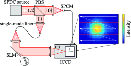
The spatial encoding of information is realized on a rectangular, virtual grid formed by binning the pixels of a camera. The experimental setup is schematized in Fig. 1 and details are given in Methods. We used a grid of areas of binned pixels, which are the symbols of our alphabet. This value corresponds to a maximum information content of bit.
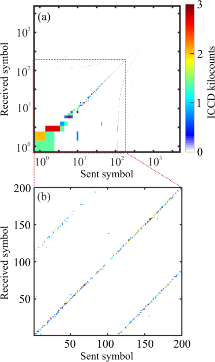
The light is directed to distinct symbols on the grid by scanning the focus using a SLM as a blazed grating. We assume that the sender has an alphabet and the receiver an alphabet . To characterize the system, we sampled the joint probability distribution , which indicates the probabilities to detect a certain symbol out of the alphabet if a symbol out of the alphabet was sent. The result is plotted in Fig. 2. The readout noise of the ICCD was reduced by applying a threshold on the measured signal to only show the intensified signal. A diagonal line in the plot of the sent symbol versus the received would indicate maximal correlation and thus bit of information. Indeed there is a strong correlation between the sent and received symbol set visible in graph (a), which shows the hole alphabet in a log-log plot. Graph (b) depicts a zoom into the first of the symbols. Due to crosstalk between the symbols, off-diagonal lines are visible, which correspond to photons hitting the symbol above or below the target. The distance of symbols between these lines and the diagonal corresponds to the column length of the grid written on the camera. The signal to the left and right of the diagonal is caused by the crosstalk between the left and right symbol on the grid. Noise can also arise from dark counts of the ICCD.
To quantify the information content per photon, we calculate the mutual information between sender and receiver. The mutual information is the measure of the average reduction in uncertainty about a sent symbol set that results from learning the value of the received symbol set ; or vice versa, the average amount of information that conveys about mackay2003information . The mutual information per detection event of the sender-receiver system is mathematically represented as
| (1) |
where is the probability that symbol is received when symbol is send and and are the overall probability to measure symbol or symbol . Theoretically, the mutual information depends on the number of symbols , which has a maximum of . The maximum number of symbols is limited by the finite size of the CCD. Using the presented binning size of the detection areas of , our theoretical limit is bit.
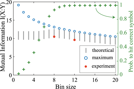
In reality, the mutual information is not only limited by the number of symbols, but also by the crosstalk between the symbols, arising from diffraction-limited focal spots, as well as the detector and background noise. In order to reduce the crosstalk between the symbols, the binning size of the detection areas can be increased. However, the limited number of pixels on the detector reduces the number of symbols. The blue circles in Fig. 3 show the dependence of the maximum mutual information for symbols made with different pixel bin sizes. The measured mutual information for and pixel bin sizes are represented as red circles, which are lower than the theoretical limit. The green markers in Fig. 3 depict the average hit probability in our experiment. By accounting for this crosstalk together with finite signal-to-dark-photocount ratio between and , we get the expected mutual information, depicted as gray bars in the figure. As evident from the figure, there is a maximal mutual information given by physical limitations of crosstalk and noise. For large bin sizes with near-zero crosstalk between symbols, one can achieve very high mutual information of over bit per photon. Given the FWHM spot size of 8 pixels, we choose an binning achieving a value of bit of mutual information per detected photon.
To calculate the mutual information per sent photon, one has to take the losses in our setup into account. This includes the coupling losses into the single mode fibres of , the diffraction losses at the SLM of , the losses at the spectral filter of and the losses at the detector due to the limited quantum efficiency of . This leads to a channel capacity of bit per photon.
III Discussion and Summary
For useful communication, the errors within the received message have to be corrected. An efficient way of error correction is the Low-Density-Parity-Check-Code (LDPC) Gallager63low-densityparity-check . In order to apply this error correction, all symbols of the set have to be translated into a bit string. Therefore we encode the and position of our symbols independently, each allocating half the bits. Since the dominant noise term is the crosstalk between the neighbouring symbols, we use a gray code gray1953pulse for each direction. This causes only one bit flip for an erroneous detection by a neighbouring symbol either in or the direction.
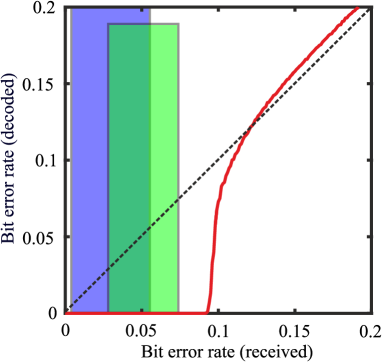
Fig. 4 shows the Bit Error Rate (BER) after error correction with LDPC versus the BER of the received bit string. The LDPC code was set to the half-rate LDPC used in digital television broadcast standard DVB-S.2. The coloured vertical bars indicate the estimated BER in case of and binning. The estimation takes the measured crosstalk between the symbols into account. Their left and right edges indicate a signal-to-dark-count photon ratio of and , respectively. For the ICCD used in these measurements, this ratio is . Other commercially available ICCD have ratios close to , explaining the choice of the other bound. Clearly, already standard error-correction code allows a practically error-free communication with the present system.
In conclusion, we demonstrate high-dimensional encoding of single photons reaching bit per photon. The capacity of this spatial encoding is only limited by the optics and the number of pixels on the detector. The channel capacity of bit can be increased by reducing the losses in the system. The main contribution to losses in our setup arises from the low quantum efficiency () of the ICCD, which can be improved to with different photocathode materials. This makes it possible to reach a signal-to-dark-count ratio of and would bring the measured values closer to its theoretical maximum. Our results are directly applicable to free-space line-of-sight communication. If the scrambling of wavefronts in multimode fibers can be controlled Cizmar:11 , a second and potentially more robust carrier for this high-dimensional encoding can be realised. A very promising direction for this work would then be the implementation of a large-spatial-alphabet encoding for quantum key distribution.
Methods
III.1 Setup
The setup is illustrated in Fig. 1. We use a Spontaneous Parametric Down-Conversion source PhysRevA.93.053817 to produce photon pairs. A mode-locked picosecond laser with a pulse repetition rate of is frequency doubled to in a LBO crystal. The frequency-doubled light is focussed in a Periodically Poled Potassium Titanyl Phosphate (PPKTP) crystal, which spontaneously produces orthogonally polarized photon pairs at a wavelength of . The entangled photon pair is separated at a Polarizing Beam Splitter into two single-photon Fock states. One of these photons is sent to a Single Photon Counting Module acting as a herald, while the second photon is directed through a single-mode fiber with a throughput of to the encoding setup. For free-space communication, one needs an encoding device at the sender position and a decoding device on the receiver position. As encoding device we use a phase-only Spatial Light Modulator to modulate the wavefront of the single photons. By writing a blazed grating on the SLM, we change the reflection angle within an angular range of in vertical and horizontal direction with a diffraction efficiency of in the first order. The Fourier transform of the SLM is imaged with a focal length lens in 2f configuration onto a large-area spatially resolving photon-counting detector. A bandpass filter at is placed in front of the detector to block stray light.
III.2 Detector
The decoding device should be able to measure the arrival of a single photon in a single shot on a large area. One technology that can potentially achieve this is the Intensified Charge-Coupled Device Jost1998 ; Abouraddy2001 ; Jedrkiewicz2004 ; Haderka2005 ; DiLorenzoPires2009 ; Aspden2013 ; Fickler2013 . ICCDs provide nanosecond gating option, which reduces the amount of dark counts significantly and makes such an ICCD capable of heralded measurements, reducing dark counts to one per thousands of readouts. The dark counts of the ICCD have their origin in thermal electrons released by the photocathode of the ICCD. Additionally, residual gas atoms can be ionized by the electron avalanche within the Microchannel Plate (MCP) of the intensifier. These ions are accelerated towards the photocathode by the MCP bias voltage, releasing secondary electron avalanches. An ion impact causes many more electrons than an incoming photon does. This leads to a local signal increase on the ICCD camera which is brighter than the signal produced by a single photon. Therefore these spurious ion signals can be filtered out in postprocessing. Our model (Andor iStar A-DH334T-18u-A3) has a quantum efficiency of . Each heralded photon from the SPDC source opens the ICCD gate for . At each position corresponding to the center of one of the symbols, images with an exposure time of have been taken. Setting a herald rate of , we measured on average photon detections per position. Measuring the FWHM of the focus with a constant phase pattern on the SLM was found to be pixels horizontally and pixels vertically.
III.3 Encoding
The target position of the photon on the ICCD is determined by the horizontal and vertical diffraction angle of the grating on the SLM. Although a scan mirror could be used for spatial encoding, a SLM is a more flexible tool. Via holography, the phase and amplitude of a wavefront can be manipulated, allowing to use complex wavefronts. Moreover, the path of the light can be corrected for disturbances using wavefront-shaping methods Vellekoop:07 . The SLM is programmed with horizontal and vertical gratings to scan over the detection plane of the ICCD. In order to define the sent symbol, the position on the ICCD has to be mapped to separate symbols. For this reason, a grid is defined on the ICCD. The pixels of the ICCD are binned together in detection areas of pixels, forming an alphabet of symbols. This rectangular map on the detection plane of the ICCD connects every detection area to an individual label, numbered from left to right and top to bottom.
Funding information
European Research Council (ERC) (279248); Stichting voor Fundamenteel Onderzoek der Materie (FOM); Nederlandse Organisatie voor Wetenschappelijk Onderzoek (NWO).
Acknowledgments
We would like to thank Klaus Boller, Boris Škorić and Willem Vos for support and discussions.
References
- (1) Nielsen, M. A. & Chuang, I. L. Quantum computation and quantum information (Cambridge university press, 2010).
- (2) Bennett, C. H. & Brassard, G. Quantum cryptography: Public key distribution and coin tossing. In International Conference on Computers, Systems & Signal Processing, Bangalore, India, Dec 9-12, 1984, 175–179 (1984).
- (3) Wootters, W. K. & Zurek, W. H. A single quantum cannot be cloned. Nature 299, 802–803 (1982).
- (4) Scarani, V. et al. The security of practical quantum key distribution. Rev. Mod. Phys. 81, 1301 (2009).
- (5) Cerf, N. J., Bourennane, M., Karlsson, A. & Gisin, N. Security of quantum key distribution using d-level systems. Phys. Rev. Lett. 88, 127902 (2002).
- (6) Bechmann-Pasquinucci, H. & Tittel, W. Quantum cryptography using larger alphabets. Phys. Rev. A 61, 062308 (2000).
- (7) Mirhosseini, M. et al. High-dimensional quantum cryptography with twisted light. New J. Phys. 17, 033033 (2015).
- (8) Mafu, M. et al. Higher-dimensional orbital-angular-momentum-based quantum key distribution with mutually unbiased bases. Phys. Rev. A 88, 032305 (2013).
- (9) Ali-Khan, I., Broadbent, C. J. & Howell, J. C. Large-alphabet quantum key distribution using energy-time entangled bipartite states. Phys. Rev. Lett. 98, 060503 (2007).
- (10) Zhong, T. et al. Photon-efficient quantum key distribution using time–energy entanglement with high-dimensional encoding. New J. Phys. 17, 022002 (2015).
- (11) Walborn, S., Lemelle, D., Almeida, M. & Ribeiro, P. S. Quantum key distribution with higher-order alphabets using spatially encoded qudits. Phys. Rev. Lett. 96, 090501 (2006).
- (12) Walborn, S., Lemelle, D., Tasca, D. & Ribeiro, P. S. Schemes for quantum key distribution with higher-order alphabets using single-photon fractional fourier optics. Phys. Rev. A 77, 062323 (2008).
- (13) Dixon, P. B., Howland, G. A., Schneeloch, J. & Howell, J. C. Quantum mutual information capacity for high-dimensional entangled states. Phys. Rev. Lett. 108, 143603 (2012).
- (14) Zhao, N., Li, X., Li, G. & Kahn, J. M. Capacity limits of spatially multiplexed free-space communication. Nat. Photonics 9, 822–826 (2015).
- (15) MacKay, D. J. Information theory, inference and learning algorithms (Cambridge university press, 2003).
- (16) Gallager, R. Low-density parity-check codes. IRE Transactions on information theory 8, 21–28 (1962).
- (17) Gray, F. Pulse code communication (1953). US Patent 2,632,058.
- (18) Čižmár, T. & Dholakia, K. Shaping the light transmission through a multimode optical fibre: complex transformation analysis and applications in biophotonics. Opt. Express 19, 18871–18884 (2011).
- (19) Wolterink, T. A. et al. Programmable two-photon quantum interference in 10 3 channels in opaque scattering media. Phys. Rev. A 93, 053817 (2016).
- (20) Jost, B., Sergienko, A., Abouraddy, A., Saleh, B. & Teich, M. Spatial correlations of spontaneously down-converted photon pairs detected with a single-photon-sensitive ccd camera. Opt. Express 3, 81–88 (1998).
- (21) Abouraddy, A. F., Nasr, M., Saleh, B. E., Sergienko, A. V. & Teich, M. C. Demonstration of the complementarity of one-and two-photon interference. Phys. Rev. A 63, 063803 (2001).
- (22) Jedrkiewicz, O. et al. Detection of sub-shot-noise spatial correlation in high-gain parametric down conversion. Phys. Rev. Lett. 93, 243601 (2004).
- (23) Haderka, O., Peřina Jr, J., Hamar, M. & Peřina, J. Direct measurement and reconstruction of nonclassical features of twin beams generated in spontaneous parametric down-conversion. Phys. Rev. A 71, 033815 (2005).
- (24) Pires, H. D. L., Monken, C. H. & van Exter, M. P. Direct measurement of transverse-mode entanglement in two-photon states. Phys. Rev. A 80, 022307 (2009).
- (25) Aspden, R. S., Tasca, D. S., Boyd, R. W. & Padgett, M. J. Epr-based ghost imaging using a single-photon-sensitive camera. New J. Phys. 15, 073032 (2013).
- (26) Fickler, R., Krenn, M., Lapkiewicz, R., Ramelow, S. & Zeilinger, A. Real-time imaging of quantum entanglement. Sci. Rep. 3 (2013).
- (27) Vellekoop, I. M. & Mosk, A. Focusing coherent light through opaque strongly scattering media. Opt. Lett. 32, 2309–2311 (2007).