Efficient Polar Code Construction
for Higher-Order Modulation
Abstract
An efficient algorithm for the construction of polar codes for higher-order modulation is presented based on information-theoretic principles. The bit reliabilities after successive demapping are estimated using the LM-rate, an achievable rate for mismatched decoding. The successive demapper bit channels are then replaced by binary input Additive White Gaussian Noise (biAWGN) surrogate channels and polar codes are constructed using the Gaussian approximation (GA). This LM-rate Demapper GA (LM-DGA) construction is used to construct polar codes for several demapping strategies proposed in literature. For all considered demappers, the LM-DGA constructed polar codes have the same performance as polar codes constructed by Monte Carlo (MC) simulation. The proposed LM-DGA construction is much faster than the MC construction. For 64-QAM, spectral efficiency 3 bits/s/Hz, and block length 1536 bits, simulation results show that LM-DGA constructed polar codes with cyclic redundancy check and successive cancellation list decoding are more power efficient than state-of-the-art AR4JA low-density parity-check codes.
I Introduction
Polar codes were proposed in [1, 2] and it was proven in [2] that they achieve the capacity of binary input discrete memoryless channels, asymptotically in the block length. The principle of polar codes is as follows. The channel input bits are transformed by a polar transformation into polarized bits. Under successive cancellation (SC) decoding, the polarized bits are either very reliable or very unreliable. The unreliable bits are frozen to predetermined values and the reliable bits are used for information transmission. The frozen bit positions define a polar code.
Polar code construction consists in choosing the frozen bit positions. Monte Carlo (MC) construction estimates the quality of the bit channels by extensive simulation [1, Sec. 6.1],[2] and is computationally demanding. MC construction for the binary input additive white Gaussian noise channel (biAWGN) is discussed in [3]. In [4], polar codes are constructed using density evolution. Approximate density evolution based on Gaussian approximations (GA) is considered in [5, 3, 6]. The authors of [5, 3] use the function introduced in [7] while [6] uses the -function [8] with the approximation [9, Eqs. (9), (10)].
In polar-coded modulation (PCM) [10] for constellations with signal points, a successive demapper (‘polar demapper’) connects binary polar codes to the bit levels of the channel inputs, see Fig. 3. MC construction for PCM was considered in [11]. The conventional GA construction can be applied to PCM by replacing the bit levels of the channel inputs by biAWGN surrogate channels (for a review of code design via surrogate channels, see [12, Sec. IV] and references therein). We call this approach the Channel GA (CGA) construction. The authors of [10] propose to characterize the bit channels of the polar demapper by mutual information (MI). They then replace the polar demapper bit channels by biAWGN surrogate channels and use GA construction. We call this method the MI demapper GA (MI-DGA) construction. The MI-DGA construction was recently used in [13]. Several polar demappers proposed in literature (e.g., in the context of bit-interleaved coded modulation (BICM)), first calculate bit-wise log-likelihood ratios (LLR), which are then processed as independent. However, LLRs calculated from the same channel output are dependent. Such demappers are therefore mismatched (‘MM’) and as we will show in this work, the MI-DGA construction does not work well for mismatched demappers.
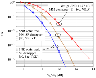
circle: MC construction.
triangle: LM-DGA construction.
In this work, we use the information-theoretic framework of mismatched decoding [14, 15]. We characterize the polar demapper bit channels by the LM-rate, which is an achievable rate under mismatched decoding. We then model the polar demapper bit channels by biAWGN channels with capacities equal to the LM-rates and use the GA construction. We evaluate this LM-DGA construction for several demappers proposed in literature. The LM-DGA constructed codes have the same performance as MC constructed codes, see Fig. 1. For the MM-SP demapper [10, Sec. V.D], the proposed LM-DGA construction is about and more power efficient than the CGA and the MI-DGA construction, respectively, see Fig. 10. For 64-QAM, spectral efficiency 3 bits/s/Hz, and block length 1536 bits, simulation results show that LM-DGA constructed polar codes with cyclic redundancy check (CRC) outer codes and SC list decoding [16] are more power efficient than state-of-the-art AR4JA [17] low-density parity-check (LDPC) codes.
This work is organized as follows. In Sec. II, we review PCM. We discuss achievable rates for polar demappers in Sec. III. In Sec. IV, we present the LM-DGA construction and compare it to the CGA and MI-DGA constructions. Sec. IV-D provides numerical results for PCM with CRC and SC list decoding with comparison to LDPC codes. We conclude in Sec. V.
II Polar-Coded Modulation
II-A Channel Model
We consider memoryless AWGN channels with bipolar amplitude shift keying (ASK) constellations and signal points given by
| (1) |
The I/O relation of the AWGN channel is
| (2) |
where is the channel input with distribution on , is the channel output and is zero mean Gaussian noise with variance one. The SNR is . Note that two real ASK symbols are equivalent to one complex quadrature amplitude modulation (QAM) symbol.
II-B Polar Coding

A binary polar code of block length and dimension is defined by frozen positions and the polar transformation , which denotes the -fold Kronecker power of the transform
| (3) |
Polar encoding can be represented by
| (4) |
where the frozen positions in are set to predetermined values and where the unfrozen positions contain the information bits. The vector is the code word. Factor graphs [18] are a convenient representation of polar codes, see Fig. 2 for . SC decoding estimates the bits successively, i.e., the channel output and the estimates are used to estimate bit . Encoding and decoding can be performed with complexity [1, Sec. 5.2.2].
II-C Polar Mapper and Demapper
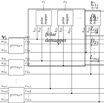
Fig. 3 displays the canonical PCM [10] scheme for -ASK constellations. Encoding works as follows. The length vector consisting of information bits and frozen bits is split into vectors , which are then mapped to vectors . A polar mapper implements a label function that maps the bits to the th transmitted ASK symbol for , i.e., for , the output of the th polar transformation is mapped to the th bit level of the labeling function.

We define the polar label
| (5) |
In the following, we will for notational convenience sometimes drop the index and write to refer to the polar label at a generic time instance.
Decoding works according to the schedule
| (6) | ||||
The polar demapper displayed in Fig. 4 passes soft-information to the th polar decoder, which returns its estimate . The polar demapper successively calculates
| (7) |
| 8-ASK symbols | -7 | -5 | -3 | -1 | 1 | 3 | 5 | 7 |
|---|---|---|---|---|---|---|---|---|
| MM Mapper [11, Sec. VII.A] | ||||||||
| BRGC | 000 | 001 | 011 | 010 | 110 | 111 | 101 | 100 |
| polar label | 000 | 111 | 001 | 110 | 010 | 101 | 011 | 100 |
| SP Mapper | ||||||||
| LSB-BRGC | 000 | 100 | 110 | 010 | 011 | 111 | 101 | 001 |
| SP polar label | 000 | 100 | 010 | 110 | 001 | 101 | 011 | 111 |
II-D Polar Demappers for 8-ASK


We next present three polar demappers for 8-ASK that have been proposed in literature.
II-D1 MM Demapper [11, Sec. VII.A]
The mapper proposed in [11, Sec. VII.A] is displayed in Table II. The polar label is first mapped to the Binary Reflected Gray Code (BRGC) [19] , which is then mapped to an 8-ASK symbol. We show the label transformation in Table II. The MM demapper is displayed in Fig. 7. The are calculated as
| (8) |
The are then combined according to Fig. 7. The boxplus operation [20, Eq. (11)] is defined by
| (9) |
The , are calculated from the same channel output and are therefore stochastically dependent. This is ignored by the boxplus operation, which assumes independence. Consequently,
| (10) |
where . The MM demapper is therefore mismatched. We discuss achievable rates for mismatched decoding in Sec. III-B.
II-D2 MM-SP Demapper [10, Sec. V.D]
In [10, Sec. V.D], the set partitioning (SP) [21] mapper is proposed for 16-ASK. The corresponding SP mapper for 8-ASK is displayed in Table II. A polar SP label is mapped to a least significant bit (LSB) BRGC, which is then mapped to an 8-ASK symbol. We show the label transformation in Table II. The demapper is shown in Fig. 7. This demapper is also mismatched.
II-D3 SP Demapper [10, Sec. IV.D]
The SP demapper calculates the soft-information for the polar SP label according to Fig. 7. The formulas in Fig. 7 directly imply that the SP demapper is matched.
Remark 1.
The SP demapper is equivalent to successively calculating the -values of one 8-ASK bit level, one 4-ASK bit level, and one 2-ASK bit level. The two mismatched demappers first calculate the -values of three 8-ASK bit levels and then calculate in addition the two boxplus operations and . Consequently, the SP demapper has lower complexity than the mismatched demappers.
III Achievable Rates of Polar Demappers
III-A Mutual Information
Mutual information is an achievable rate for reliable communication [22, Sec. 5.6]. Consider a memoryless channel and a random codebook with entries independent and identically distributed according to on . The message is uniformly distributed on , i.e., the rate is bits per channel use. A maximum likelihood (ML) decoder uses as decoding metric, i.e.,
| (11) |
The average probability of erroneous ML decoding of the random code ensemble approaches zero for approaching infinity if
| (12) |
III-B LM-Rate
Using a metric different from is called mismatched decoding [14]. A mismatched decoder uses a function , called auxiliary channel, as decoding metric, i.e.,
| (13) |
Define
| (14) |
where is the corresponding auxiliary output distribution, where , and where is a real-valued function defined on with finite expectation . By [14], the probability of erroneous mismatched decoding approaches zero for approaching infinity if
| (15) |
Lemma 1.
We have , with equality if and , .
Maximizing over yields the LM-Rate [14]
| (16) |
Remark 2.
Setting and maximizing over yields the generalized mutual information (GMI) as defined in [23].
III-C LM-Rate for Polar Demappers
We now evaluate the LM-Rate for the metric
| (17) |
where is the demapper output providing soft-information about bit . For the metric (17), the LM-rate becomes
| (18) |
Lemma 2.
For
| (19) |
we have
| (20) |
Proof:
We provide a proof in the Appendix. ∎
We can now estimate an achievable rate for each bit level of a polar demapper. It is given by
| (21) |
III-D Polar Demapper Achievable Rates for 8-ASK
In Table III, we display the LM-rates at for the bit-channels created by the MM demapper, the MM-SP demapper, and the SP demapper. The MM-SP and the SP demapper polarize more than the MM demapper. The SP demapper has the greatest sum rate. Note that this qualitatively corresponds to the ordering of the corresponding FER curves in Fig. 1. For the MM demapper and the MM-SP demapper, we also display the MIs of the bit-channels before polar demapping. Both demappers have the same MIs in different order. Note that the bit-channels before polar demapping are much less polarized than after polar demapping.
| Polar demapper bit-channel achievable rates | ||||
|---|---|---|---|---|
| MM Demapper Fig. 7 | 0.1294 | 0.9109 | 0.8212 | 1.8615 |
| MM-SP Demapper Fig. 7 | 0.1295 | 0.7397 | 0.9885 | 1.8577 |
| SP Demapper Fig. 7 | 0.1312 | 0.7503 | 0.9986 | 1.8801 |
| Bit-channel achievable rates | ||||
| MM Demapper Fig. 7 | 0.8319 | 0.6641 | 0.3589 | 1.8548 |
| MM-SP Demapper Fig. 7 | 0.3589 | 0.6641 | 0.8319 | 1.8548 |
IV Construction by Surrogates
IV-A biAWGN Surrogate Channel
The biAWGN channel is (2) for , i.e.,
| (22) |
where and . The mutual information of input uniformly distributed on and biAWGN output is
| (23) |
IV-B Gaussian Approximation
The reliability of the bit , can be quantified by the MI . We can calculate these MIs by recursively calculating the MIs of the basic polar transform displayed in Fig. 8.

IV-C Construction Methods
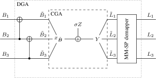
We next discuss three variants of the GA construction. For illustrative purpose, we explain it for the 8-ASK MM-SP demapper. In Fig. 9, MM-SP mapper, AWGN channel, and MM-SP demapper are displayed. The CGA construction connects and by a biAWGN channel with noise variance given by
| (29) |
The MI-DGA construction connects and by a biAWGN channel with noise variance
| (30) |
The LM-DGA construction connects and by a biAWGN channel with noise variance
| (31) |
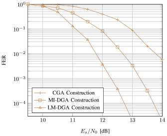
In Fig. 10, we show the FER performance for the three construction methods for the MM-SP demapper. The LM-DGA constructed code performs best and the CGA construction performs worst.
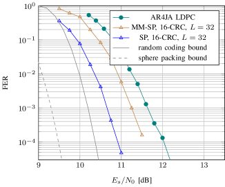
IV-D SC List Decoding
In Fig. 11, we show results for LM-DGA constructed polar codes combined with 16-CRC and SC list decoding [16] with list size . As a reference, Shannon’s sphere packing bound [24, Eqs. (3), (17)] and Gallager’s random coding bound [22, Theorem 5.6.2] are shown as well. Both with an MM-SP and an SP demapper, the polar codes perform better than an AR4JA LDPC code [17] decoded with 200 full sum-product belief propagation iterations. At FER , the polar code with SP demapper is more power efficient than the LDPC code and is within of the random coding bound.
V Conclusions
In this work, we have developed the LM-rate demapper Gaussian approximation (LM-DGA) method to construct polar codes for higher-order modulation. We have shown that in contrast to GA construction methods previously proposed in literature, the LM-DGA construction works also for mismatched demappers, i.e., the LM-DGA constructed polar codes have the same performance as codes constructed by Monte Carlo simulation. With CRC outer codes and list decoding, the LM-DGA constructed polar codes outperform state-of-the-art LDPC codes. An interesting problem for future research are performance guarantees for mismatched demappers.
Proof:
For
| (32) |
we have
| (33) |
We have
| (34) | |||
| (35) |
Continuing the last equation, we have
| (36) | |||
| (37) |
∎
References
- [1] N. Stolte, “Rekursive Codes mit der Plotkin-Konstruktion und ihre Decodierung,” Ph.D. dissertation, TU Darmstadt, 2002.
- [2] E. Arıkan, “Channel polarization: A method for constructing capacity-achieving codes for symmetric binary-input memoryless channels,” IEEE Trans. Inf. Theory, vol. 55, no. 7, pp. 3051–3073, Jul. 2009.
- [3] H. Vangala, E. Viterbo, and Y. Hong, “A comparative study of polar code constructions for the AWGN channel,” arXiv preprint, 2015. [Online]. Available: https://arxiv.org/pdf/1501.02473v1.pdf
- [4] R. Mori and T. Tanaka, “Performance of polar codes with the construction using density evolution,” IEEE Commun. Lett., vol. 13, no. 7, pp. 519–521, Jul. 2009.
- [5] P. Trifonov, “Efficient design and decoding of polar codes,” IEEE Trans. Commun., vol. 60, no. 11, pp. 3221–3227, Nov. 2012.
- [6] D. Dosio, “Polar codes for error correction: analysis and decoding algorithms,” Master’s thesis, University of Bologna, 2016.
- [7] S. Y. Chung, T. J. Richardson, and R. L. Urbanke, “Analysis of sum-product decoding of low-density parity-check codes using a Gaussian approximation,” IEEE Trans. Inf. Theory, vol. 47, no. 2, pp. 657–670, Feb. 2001.
- [8] S. ten Brink, G. Kramer, and A. Ashikhmin, “Design of low-density parity-check codes for modulation and detection,” IEEE Trans. Commun., vol. 52, no. 4, pp. 670–678, Apr. 2004.
- [9] F. Brännström, L. K. Rasmussen, and A. J. Grant, “Convergence analysis and optimal scheduling for multiple concatenated codes,” IEEE Trans. Inf. Theory, vol. 51, no. 9, pp. 3354–3364, Sep. 2005.
- [10] M. Seidl, A. Schenk, C. Stierstorfer, and J. B. Huber, “Polar-coded modulation,” IEEE Trans. Commun., vol. 61, no. 10, pp. 4108–4119, Oct. 2013.
- [11] H. Mahdavifar, M. El-Khamy, J. Lee, and I. Kang, “Polar coding for bit-interleaved coded modulation,” IEEE Trans. Veh. Technol., vol. 65, no. 5, pp. 3115–3127, May 2016.
- [12] F. Steiner, G. Böcherer, and G. Liva, “Protograph-based LDPC code design for shaped bit-metric decoding,” IEEE J. Sel. Areas Commun., vol. 34, no. 2, pp. 397–407, Feb. 2016.
- [13] S. R. Tavildar, “Bit-permuted coded modulation for polar codes,” arXiv preprint, 2016. [Online]. Available: https://arxiv.org/pdf/1609.09786v1.pdf
- [14] A. Ganti, A. Lapidoth, and E. Telatar, “Mismatched decoding revisited: General alphabets, channels with memory, and the wide-band limit,” IEEE Trans. Inf. Theory, vol. 46, no. 7, pp. 2315–2328, Nov. 2000.
- [15] G. Böcherer, “Achievable rates for shaped bit-metric decoding,” arXiv preprint, 2016. [Online]. Available: http://arxiv.org/abs/1410.8075
- [16] I. Tal and A. Vardy, “List decoding of polar codes,” IEEE Trans. Inf. Theory, vol. 61, no. 5, pp. 2213–2226, May 2015.
- [17] D. Divsalar, S. Dolinar, C. R. Jones, and K. Andrews, “Capacity-approaching protograph codes,” IEEE J. Sel. Areas Commun., vol. 27, no. 6, pp. 876–888, Aug. 2009.
- [18] F. R. Kschischang, B. J. Frey, and H.-A. Loeliger, “Factor graphs and the sum-product algorithm,” IEEE Trans. Inf. Theory, vol. 47, no. 2, pp. 498–519, Feb. 2001.
- [19] F. Gray, “Pulse code communication,” U. S. Patent 2 632 058, 1953.
- [20] J. Hagenauer, E. Offer, and L. Papke, “Iterative decoding of binary block and convolutional codes,” IEEE Trans. Inf. Theory, vol. 42, no. 2, pp. 429–445, Mar. 1996.
- [21] G. Ungerböck, “Channel coding with multilevel/phase signals,” IEEE Trans. Inf. Theory, vol. 28, no. 1, pp. 55–67, Jan. 1982.
- [22] R. G. Gallager, Information Theory and Reliable Communication. John Wiley & Sons, Inc., 1968.
- [23] G. Kaplan and S. Shamai (Shitz), “Information rates and error exponents of compound channels with application to antipodal signaling in a fading environment,” AEÜ, vol. 47, no. 4, pp. 228–239, 1993.
- [24] C. E. Shannon, “Probability of error for optimal codes in a Gaussian channel,” Bell Syst. Tech. J., vol. 38, no. 3, pp. 611–656, May 1959.