mifechaBilbao, a \THEDAY de \monthname[\THEMONTH] de \THEYEAR
![[Uncaptioned image]](/html/1610.08293/assets/x1.png)
UNIVERSIDAD CARLOS III DE MADRID
TESIS DOCTORAL
Opportunistic Device-to-Device Communication in Cellular networks: From Theory to Practice
| Autor: | Arash Asadi, IMDEA Networks Institute, University Carlos III of Madrid |
|---|---|
| Director: | Vincenzo Mancuso, IMDEA Networks Institute |
| Tutor: | Ruben Cuevas Rumin, University Carlos III of Madrid |
DEPARTAMENTO DE INGENIERÍA TELEMÁTICA
Leganés (Madrid), \monthname de 2024
![[Uncaptioned image]](/html/1610.08293/assets/x2.png)
UNIVERSIDAD CARLOS III DE MADRID
PH.D. THESIS
Opportunistic Device-to-Device Communication in Cellular networks: From Theory to Practice
| Author: | Arash Asadi, IMDEA Networks Institute, University Carlos III of Madrid |
|---|---|
| Director: | Vincenzo Mancuso, IMDEA Networks Institute |
| Tutor: | Ruben Cuevas Rumin, University Carlos III of Madrid |
DEPARTMENT OF TELEMATIC ENGINEERING
Leganés (Madrid), \monthname 2024
Opportunistic Device-to-Device Communication in Cellular networks: From Theory to Practice
A dissertation submitted in partial fulfillment of the requirements for the degree of Doctor of Philosophy
Prepared by
Arash Asadi, IMDEA Networks Institute, University Carlos III of Madrid
Under the advice of
Vincenzo Mancuso, IMDEA Networks Institute
Ruben Cuevas Rumin, University Carlos III of Madrid
Departamento de Ingeniería Telemática, Universidad Carlos III de Madrid
Date: \monthname, 2024
Web/contact: arash.asadi@imdea.org
This work has been supported by IMDEA Networks Institute.
TESIS DOCTORAL
Opportunistic Device-to-Device Communication in Cellular networks: From Theory to Practice
| Autor: | Arash Asadi, IMDEA Networks Institute, University Carlos III of Madrid |
|---|---|
| Director: | Vincenzo Mancuso, IMDEA Networks Institute |
| Tutor: | Ruben Cuevas Rumin, University Carlos III of Madrid |
Firma del tribunal calificador:
Presidente: Prof. Douglas Leith
Vocal: Dr. Carla Fabiana Chiasserini
Secretario: Prof. Albert Banchs
Calificación:
Leganés, de de
Acknowledgements
First and foremost I want to thank my advisor Vincenzo Mancuso. It has been an honor to be his first Ph.D. student. I appreciate all his contributions, the late nights spent on reviewing my papers, funding to make my Ph.D. experience productive and stimulating, and insightful discussions about my research. I also have to thank the members of my PhD committee.
My special thanks goes to my other Ph.D. fellows, Ignacio De Castro Arribas, Thomas Nitsche, and Qing Wang with whom I had long meetings in our favorite meeting room (a.k.a, kitchen). I am grateful to Christian Vitale and Vincenzo Sciancalepore for their collaborations.
I will forever be thankful to my life partner, Allyson Sim, whose support and enthusiasm was vital to my progress within the past 6 years. I hope I can return her support and kindness for years to come.
Last, but by no means least, thanks go to mum, dad and my sister for almost unbelievable support. They are the most important people in my world and I dedicate this thesis to them.
Abstract
Cellular service providers have been struggling with users’ demand since the emergence of mobile Internet. As a result, each generation of cellular network prevailed over its predecessors mainly in terms of connection speed. However, the fifth generation (5G) of cellular network promises to go beyond this trend by revolutionizing the network architecture. Device-to-Device (D2D) communication is one of the revolutionary changes that enables mobile users to communicate directly without traversing a base station. This feature is being actively studied in 3GPP with special focus on public safety as it allows mobiles to operate in adhoc mode. Although under the (partial) control of the network, D2D communications open the door to many other use-cases.
This dissertation studies different aspects of D2D communications and its impact on the key performance indicators of the network. We design an architecture for the collaboration of cellular users by means of timely exploited D2D opportunities. We begin by presenting the analytical study on opportunistic outband D2D communications. The study reveals the great potential of opportunistic outband D2D communications for enhancing energy efficiency, fairness, and capacity of cellular networks when groups of D2D users can be form and managed in the cellular network. Then we introduce a protocol that is compatible with the latest release of IEEE and 3GPP standards and allows for implementation of our proposal in a today’s cellular network. To validate our analytical findings, we use our experimental Software Defined Radio (SDR)-based testbed to further study our proposal in a real world scenario. The experimental results confirm the outstanding potential of opportunistic outband D2D communications. Finally, we investigate the performance merits and disadvantages of different D2D “modes”. Our investigation reveals, despite the common belief, that all D2D modes are complementary and their merits are scenario based.
- AADTR
- Average Absolute Deviation of Transmission Rate
- ADC
- Analog to Digital Conversion
- AMBR
- Aggregate Maximum Bit Rate
- ARP
- Allocation and Retention Priority
- BCH
- BE
- Best Effort
- BITS
- BS-drIven Traffic Spreading
- BS
- Base Station
- BSR
- Buffer Status Report
- C-RNTI
- Cell Radio Network Temporary Identifier
- CAC
- Call Admission Control
- CCH
- Control CHannel
- CDF
- Cumulative Distribution Function
- CEB
- Cooperative Eigen Beamforming
- CL(MR)
- Cluster Max Rate
- CL(WRR)
- Cluster Weighted Round Robin
- CQI
- Channel Quality Indicator
- CSI
- Channel State Information
- D2D
- Device-to-Device
- DAC
- Digital to Analog Conversion
- DCI
- Downlink Control Information
- DHCP
- Dynamic Host Configuration Protocol
- DORE
- D2D Opportunistic Relay with QoS-Enforcement
- DRONEE
- Dual Radio Opportunistic Networking for Energy Efficiency
- DRX
- Discontinuous Reception
- DSP
- Digital Signal Processing
- E-RAB
- E-UTRAN Radio Access Bearer
- EPC
- Evolved Packet Core
- EPS
- Evolved Packet System
- ES
- Equal Share
- FAM
- FlexRIO Adaptor Module
- FFT
- Fast Fourier Transform
- FPGA
- Field Programmable Gate Array
- FSMC
- Finite State Markov Chain
- GBR
- Guaranteed Bit Rate
- GO
- Group Owner
- GUTI
- Globally Unique Temporary UE Identity
- HARQ
- Hybrid Automatic Repeat Request
- ICI
- Inter Cell Interference
- IE
- Information Element
- iFFT
- inverse Fast Fourier Transform
- IM
- Implementation Margin
- IMEI
- International Mobile Equipment Identity
- IMSI
- International Mobile Subscriber Identity
- ISM
- Industrial, Scientific and Medical
- LTE
- Long Term Evolution
- M-LWDF
- Modified Largest Weighted Delay First
- MBR
- Maximum Bit Rate
- MCS
- Modulation and Coding Scheme
- MME
- Mobility Management Entity
- MR
- Max Rate
- NAS
- Non Access Stratum
- OFDM
- Orthogonal Frequency-Division Multiplexing
- OFDMA
- Orthogonal Frequency-Division Multiple Access
- OTA
- Over The Air
- P-GW
- PDN Gateway
- PCEF
- Policy and Charging Enforcement Function
- PCRF
- Policy and Charging Rules Function
- PDCCH
- Physical Downlink Control CHannel
- PDCP
- Packet Data Convergence Protocol
- PDN
- Packet Data Network
- PDSCH
- Physical Downlink Shared CHannel
- PDU
- Packet Data Unit
- PDU
- Packet Data Unit
- PF
- Proportional Fair
- ProSe
- Proximity-based Services
- PSNR
- Peak Signal-to-Noise Ratio
- PUCCH
- Physical Uplink Control CHannel
- PUSCH
- Physical Uplink Shared CHannel
- QCI
- QoS Class Identifier
- QoE
- Quality of Experience
- QoS
- Quality of Service
- RF
- Radio Frequency
- RLC
- Radio Link Control
- RR
- Round Robin
- RRC
- Radio Resource Control
- S-GW
- Serving Gateway
- S-TMSI
- SAE-Temporary Mobile Subscriber Identity
- SAE
- System Architecture Evolution
- SC-FDMA
- Single Carrier-FDMA
- SCH
- Shared CHannel
- SDR
- Software Defined Radio
- SDU
- Service Data Unit
- SINR
- Signal-to-Interference-plus-Noise Ratio
- SNR
- Signal-to-Noise Ratio
- SR
- Scheduling Request
- SRB
- Signaling Radio Bearer
- SS
- Shapely Share
- SSIM
- Structural Similarity
- TB
- Transport Block
- TDMA
- Time Division Multiple Access
- TEID
- Tunneling Endpoint ID
- TFT
- Traffic Flow Template
- TMSI
- Temporary Mobile Subscriber Identity
- UE
- User Equipment
- UIT
- Uplink Information Transfer
- WPS
- Wireless Protected Setup
- WRR
- Weighted Round Robin
- WS
- Weighted Share
- WSL
- Workload-base Scheduling with Learning
Chapter 1 Introduction
The emergence of smartphones and their ever expanding role in our daily life transformed the cellular networks from an option to a necessity. This transformation created a flow of cash to the cellular operators’ accounts and traffic to their infra-structure. Initially, the operators leveraged the former to support the latter. Their first actions were increasing the number of base stations and buying more bandwidth to improve the cellular network capacity. However, these measures did not help the operators to catch up with the traffic demand of mobile users’. Next step was to exploit the cellular resources in a more efficient manner. As a result, the 3rd and 4th generation (3G and 4G) of cellular technologies (e.g., UMTS and LTE) demonstrated more efficient resource utilization in comparison to their predecessors. In particular, use of opportunistic scheduling techniques [1] to leverage wireless channel diversities among cellular users become customary. Nevertheless, operators were still lagging behind mobile users’ booming traffic demand. Finally, some realized that while the application of cellular networks has evolved tremendously within the past 20 years, its network architecture changed very little. This triggered an architectural revolution towards 5G cellular standards and introduced a new paradigm called D2D communication [2].
D2D communication in cellular networks is defined as direct communication between mobile users without traversing the Base Station (BS) or core network. In a traditional cellular network, all communications must go through the BS even if both communicating parties are in range for direct communication. This architecture suits the conventional low data rate mobile services such as voice call and text message in which end users are not usually close enough to have direct communication. However, mobile users in today’s cellular networks use high data rate for services (e.g., video sharing, gaming, proximity-aware social networking) that involve users potentially in range of direct communications (i.e., D2D). Hence, D2D communications in such scenarios can highly increase the spectral efficiency of the network not only because of avoiding unnecessary transmissions to and from the BS, but also because of the higher data rates achievable at lower power levels when users are in proximity. Nevertheless, the advantages of D2D communication is not only limited to enhanced spectral efficiency.
The advent of D2D communication has set off numerous proposals in industry and academia to improve the performance of cellular networks. As of today there are not only several proposals for cellular relaying, multicasting, cellular offloading, and content distribution leveraging D2D [3, 1], but also entire system architectures based on D2D to complement cellular-based services in a scalable way with new types of applications [4]. In addition to academia and telecommunication companies, 3GPP is also investigating D2D communications as Proximity Services (ProSe) [5]. Indeed, 3GPP is actively studying the feasibility and the architecture of ProSe to finalize the standardization process for both inband and outband D2D modes, in which inband D2D uses the cellular spectrum, while outband D2D uses unlicensed spectrum. In particular, the feasibility of ProSe and its use-cases in LTE are studied in [5] and the required architectural enhancements to accommodate such use-cases are investigated in [6]. Release 12 of 3GPP already specifies system overview and discovery procedure of D2D communications. Moreover, there are still ongoing studies on architecture enhancements and radio management aspects of D2D [7, 8].
So far, only the operator’s infra-structure was involved in data delivery. By allowing mobile users to relay the cellular traffic for other users, D2D communications unleash the true potentials of user cooperations. Hence, mobile users have a chance to join forces with the operators and leverage cooperative communication techniques to enhance the resource utilization efficiency using more aggressive opportunistic scheduling schemes.
In this dissertation, we cover various aspects and use-cases of D2D communication. Indeed, we pioneer to propose outband D2D communications and to design adaptive multi-band multi-mode D2D communication. The main contributions of this dissertation are:
-
We provide a model for throughput and energy consumption for opportunistic outband D2D-clustering under LTE-A and WiFi Direct technologies;
-
We use coalitional game theory to study the revenue distribution and fairness in presence of opportunistic outband D2D-clustering;
-
We propose the first protocol that accommodates network-assisted D2D clustering within the current LTE-A and WiFi Direct framework with minor changes to the existing network architecture and protocols;
-
We use the state-of-the-art SDR platforms to implement the first outband D2D prototype in order to verify our analytical findings with real world experiments;
-
We propose floating band D2D technique in which D2D users leverage a multi-mode multi-band D2D environment;
-
We are the first to use the properties of D2D to improve fairness of MaxRate scheduler without any throughput penalty by exploiting smart tie-breaking schemes.
1.1 Roadmap
This dissertation starts with a short background on opportunistic scheduling and D2D communications in cellular networks to familiarize the reader with the terminology and the state-of-the-art. Next, we study our proposed network-assisted D2D clustering techniques in which we show the merits of simple opportunistic scheduling and cooperative communication techniques in D2D architecture. Then, we address the problem of mode selection in D2D-enabled networks. Finally, we investigate our proposed D2D tie-breaking mechanism to improve user fairness without impacting the aggregate system throughput. In the following, we provide more details about each of these parts composing this dissertation.
1.1.1 Network-Assisted D2D Clustering
From Chapter 3 to 5, we present a channel-opportunistic architecture that leverages outband D2D communications and opportunistic clustering techniques. Specifically, we build on top of the forthcoming D2D features of LTE-A networks, and on WiFi Direct. In our proposal, mobile users form clusters opportunistically, in which only the user with the best channel condition communicates with the base station on behalf of the entire cluster. Within the cluster, WiFi Direct is used to relay traffic. Our architecture benefits D2D users in terms of throughput and energy efficiency, for which we provide an analytical model. In addition, we use coalitional game theory to find a suitable payoff distribution among D2D users. Focusing on the implementation feasibility of D2D communications in a network controlled by an operator, we introduce a D2D protocol based on the features of LTE-A and WiFi Direct. We use simulations and real experiments to validate the superiority of D2D-based cluster communication schemes over conventional cellular communications in terms of throughput, delay, fairness and energy efficiency. In particular, we develop D2D Opportunistic Relay with QoS-Enforcement (DORE) algorithm in our experimental evaluation that is based on algorithms used in our simulation with an additional delay-awareness feature. The results of the work presented in these chapters appeared in three peer-reviewed journal articles [2, 1, 9], one magazine article [10], six conference papers [11, 12, 13, 14, 15, 16], three posters [17, 18, 19], and one demo [20].
1.1.2 D2D for Network Optimization
In Chapter 6, we propose Floating Band D2D, an adaptive framework to exploit the full potential of D2D transmission modes. We show that inband and outband D2D modes exhibit different pros and cons in terms of complexity, interference, and spectral efficiency. Moreover, none of these modes are suitable as a one-size-fits-all solution for today’s cellular networks, due to diverse network requirements and variable users’ behavior. Therefore, we unveil the need for going beyond traditional single-band mode-selection schemes. Specifically, we model and formulate a general and adaptive multi-band mode selection problem, namely Floating Band D2D. The problem is NP-hard, so we propose simple yet effective heuristics. Our results show the superiority of the Floating Band D2D framework, which dramatically increases network utility and achieves near complete fairness. The results of the work presented in this chapter appeared into two conferences [21, 22] and one peer-reviewed journal [23].
Opportunistic schedulers such as MaxRate and Proportional Fair are known for trading off throughput and fairness of users in cellular networks. In Chapter 7, we show how to achieve maximum fairness without sacrificing throughput. We propose a novel solution that integrates opportunistic scheduling design principles and cooperative D2D communications capabilities in order to improve both fairness and capacity in cellular networks. We develop a mathematical approach and design smart tie-breaking mechanisms which enhance the fairness achieved by the MaxRate scheduler. We show that users that cooperatively form clusters benefit from both higher throughput and fairness. Our scheduling mechanism is simple to implement and scales linearly with the number of clusters, and is able to achieve equal or better fairness than Proportional Fair schedulers. The results of the work presented in this chapter is still under review process in a journal and a conference. However, part of the results is already presented in one demo [24].
1.2 Publications
The research performed in this dissertation resulted in eight conference/workshop papers [11, 12, 21, 13, 14, 22, 15, 16], four journal articles [2, 1, 9, 23], one magazine article [10], four posters [17, 18, 24, 19] and one demo [20]. In this section, we elaborate on the goal of each paper and the author’s contribution.
The following surveys are the outcome of our literature review and investigation into open problems in opportunistic scheduling and D2D communications in cellular networks.
-
Arash Asadi and Vincenzo Mancuso , “A Survey on Opportunistic Scheduling in Wireless Communications”, IEEE Surveys and Tutorials on Communications, 2013.
-
Arash Asadi , Qing Wang, and Vincenzo Mancuso , “A Survey on Device-to-Device Communication in Cellular Networks”, IEEE Surveys and Tutorials on Communications, 2014.
We published our proposed architecture for opportunistic outband D2D-clustering and the analytical models for the throughput and the energy consumption of dual-radio devices using LTE-A and WiFi direct in the the following papers.
-
Arash Asadi and Vincenzo Mancuso, “Energy Efficient Opportunistic Uplink Packet Forwarding in Hybrid Wireless Networks”, in Proceeding of the ACM International Conference on Future Energy Systems (e-Energy), Berkeley, CA, USA, 2013.
-
Arash Asadi and Vincenzo Mancuso, “On the Compound Impact of Opportunistic Scheduling and D2D Communications in Cellular Networks”, in Proceeding of the ACM International Conference on Modeling, Analysis and Simulation of Wireless and Mobile Systems (MSWIM), Barcelona, Spain, 2013.
-
Arash Asadi and Vincenzo Mancuso , “DRONEE: Dual-radio Opportunistic Networking for Energy Efficiency”, Elsevier Computer Communications, 2014.
Our Wireless Days paper is dedicated to design of a protocol for D2D-clustering that can be easily adapted to the current LTE-A and WiFi Direct architecture. In this paper, we also evaluate the performance of our proposal using packet-level simulation.
-
Arash Asadi and Vincenzo Mancuso, “WiFi Direct and LTE D2D in Action”, in Proceeding of the IEEE Wireless Days, Valencia, Spain, 2013 .
Our INFOCOM paper focuses on a 3GPP compliant structure for outband D2D communications. We also present the first SDR-based outband D2D communication platform and its performance metrics in this paper.
-
Arash Asadi , Vincenzo Mancuso and Rohit Gupta, “An SDR-based Experimental Study of Outband D2D Communications’, in Proceeding of the IEEE INFOCOM, San Francisco, USA, 2016.
The floating band idea is presented in the following papers. These papers highlight the importance of adaptability and use of all D2D modes in D2D communications. Our contributions in these papers are the idea, evaluation and assistance in the development of the mathematical analysis.
-
Arash Asadi , Peter Jacko, and Vincenzo Mancuso , “Modeling D2D Communications with LTE and WiFi”, ACM SIGMETRICS Performance Evaluation Review, 2014.
-
Arash Asadi, Vincenzo Mancuso, and Peter Jacko, “Floating Band D2D: Exploring and Exploiting the Potentials of Adaptive D2D-enabled Networks”, in Proceeding of the IEEE International Symposium on a World of Wireless, Mobile and Multimedia Networks (WoWMoM), Boston, MA, USA, 2015.
We collaborated with many researchers within the course of this dissertation, especially in the framework of EU FP7 CROWD111www.ict-crowd.eu project. The following papers are the results of these collaborations. Our contributions are mainly the analysis and evaluation of D2D communications and opportunistic scheduling.
-
Arash Asadi, Vincenzo Sciancalepore, and Vincenzo Mancuso, “On the Efficient Utilization of Radio Resources in Extremely Dense Wireless Networks”, IEEE Communication Magazine, 2015.
-
Christian Vitale, Vincenzo Sciancalepore, Arash Asadi, “Two-level Opportunistic Spectrum Management for Green 5G Radio Access Networks”, Accepted for publication in IEEE Online International Conference on Green Computing and Communications, 2015.
-
Rohit Gupta, Bjoern Bachmann, Andreas Kruppe, Russell Ford, Sundeep Rangan, Nikhil Kundargi, Amal Ekbal, Karamavir Rathi, Arash Asadi, Vincenzo Mancuso, and Arianna Morelli, “Labview Based Software-Defined Physical/Mac Layer Architecture For Prototyping Dense LTE Networks”, in Proceeding of the Wireless Innovation Forum Conference on Wireless Communications Technologies and Software Defined Radio, San Diego, CA, USA, 2015.
-
Maria Isabel Sanchez, Arash Asadi, Martin Draexler, Rohit Gupta, Vincenzo Mancuso, Arianna Morelli, Antonio De la Oliva, Vincenzo Sciancalepore, “Tackling the Increased Density of 5G Networks; the CROWD Approach”, in Proceeding of the 1st International Workshop on 5G Architecture co-located with VTC-spring, 2015.
Chapter 2 Background
In this chapter, we provide the reader with a thorough review on the-state-of-the art in opportunistic scheduling and D2D communications in cellular networks based on our propose taxonomy. This chapter include various tables which comparison a handful of related work which may have not been elaborated in details for brevity. Nevertheless, interested reader can find further details in [1, 2] for such articles. In addition to literature review, we conclude each group of works with a discussion on short-comings of the current works, open issues and the future trends.
2.1 Opportunistic Scheduling
Opportunistic schedulers take into account information such as the channel quality in terms of Quality of Service (QoS) metrics (i.e., throughput, delay, jitter) that allows the scheduler to find the proper transmission resources for each user. The notion of opportunistic scheduling was first introduced by Knopp and Humblet in [25]. They showed that using the multiuser diversity in scheduling process can significantly improve the capacity. In a pure opportunistic approach, the scheduler always chooses the user in the best channel condition to use the resources. This approach is referred to as MaxRate scheduling in the literature. The gain in opportunistic scheduling depends on the multiuser diversity due to random wireless channel impairments such as fading and multipath. After [25], researchers aimed to take advantage of diversity caused by the channel impairments instead of eliminating it. Some authors even propose techniques such as opportunistic beamforming to increase the multiuser diversity [26, 27, 28]. With this technique, the same signal is transmitted over multiple antennas with different transmission powers. This increases the channel diversity of users, which leads to improved opportunistic gain. MaxWeight [29] is another opportunistic scheduler that selects the user with the highest product of queue length and transmission rate. MaxWeight was considered throughput-optimal before the authors in [30] prove otherwise under flow level dynamics. However, MaxWeight is throughput-optimal with fully backlogged queues. Exp rule schedulers [31] are throughput-optimal schedulers that prioritize users based on an exponential formula using queue size and transmission rate of every user. Opportunistic scheduling has been proposed not only to improve capacity or QoS. For instance, Wong et al. proposed an opportunistic scheduling strategy to leverage multiuser diversity in an Orthogonal Frequency-Division Multiplexing (OFDM) systems and do attempt to minimize the overall transmission power [32].
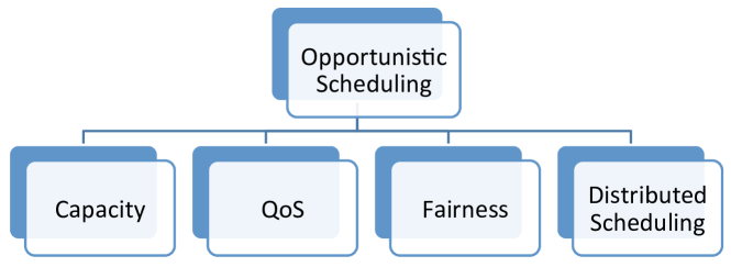
The available literature on opportunistic scheduling tackles the issue of scheduling from different aspects. Most of these proposals are subclasses of four major categories: capacity, QoS, fairness, and distributed scheduling. Proposals that purely improve network capacity regardless of QoS or fairness implications are listed under the first category. Here, we review the existing literature based on the proposed taxonomy, which is schematically depicted in Figure 2.1.
2.1.1 Capacity-oriented Opportunistic Schedulers
In many proposals, opportunistic scheduling is employed as a solution to enhance the total capacity of wireless networks.
In many wireless technologies, users can transmit over more than one carrier. This ability extends the opportunistic scheduling decision process to carrier allocation among users. Andrews and Zhang [33] tackle the problem of scheduling in a multi-carrier wireless system. Their work is dedicated to adapt the MaxWeight algorithm for multi-carrier scenarios for which they define three objective functions that emulate the MaxWeight behavior. The first objective function simply maximizes the product of queue size and feasible rate for each user over all subcarriers. The second and third objective functions are NP-hard problems that account for the ignorance of MaxWeight algorithm towards users with small queue and bad channel quality, as discussed in [30]. To serve this purpose, the second objective function prioritizes the users with small queues and the third objective function maximizes the negative drift of a Lyapunov function [34] (i.e., maximizes the queue length variation in every slot). The authors propose five algorithms based on the objective functions defined for MaxWeight. The algorithms which are derived from second and third objectives inherit the NP-hardness. The authors solve the NP-hard algorithms via approximations and prove their stability. The simulation results showed that the algorithms based on the second and third objective provide better performance. They also show that the algorithms which optimize the scheduling decision over all carriers instead of local carrier optimization outperform the rest.
In [35], Liu et al. propose a throughput-optimal scheduler that does not require any prior knowledge of channel state and user demands. This can be achieved using the so called Workload-base Scheduling with Learning (WSL). The authors define the flows that continuously inject traffic as long-lived and those with finite number of bits as short-lived. In order to find the maximum possible data rate of short-lived flows, their data rate is monitored for a learning period. The authors of [35] also provide the necessary conditions for stability of a scheduler which is: the service allocated to each user should not be less than what was requested if the service were supportable at all. the total airtime allocated to short-lived and long-lived flows should be less than or equal than the total available time . The authors prove that WSL is throughput-optimal.
In the same work, Liu et al. discuss the basic problem of MaxWeight, e.g., a flow with small backlog may never be served. A solution for this problem is to use the product of the head of line delay (delay-based scheduling). However, in [35] it is shown that the delay-based scheduler is also not stable in presence of short-lived flows. The authors conclude with a set of simulations to evaluate the performance of WSL, MaxWeight, and delay-based scheduler. They show that WSL can sustain a zero blocking probability while admitting almost 20% more traffic. WSL also shows better delay performance.
Table 2.1 shows each proposal mainly focusing on capacity with details regarding the assumptions taken by the authors, analytical tools used for the proposals, the scenario in which the proposal in applicable, and other considerations taken into account besides capacity improvement.
Proposal Assumptions Analytical tools Topology Other focus Scheduler for multicarrier Full Channel State Information (CSI) Greedy algorithms Single cell (OFDMA) Fairness wireless system [33] Not fully backlogged Dynamic programming Multi-carrier Stability Traffic: Generic Linear programming Downlink Lyapunov drift Scheduler for multichannel Full CSI Markov chain Single cell (OFDM) Throughput-optimal wireless systems with Not fully backlogged Lagrangian multipliers Multi-carrier Stability flow-level dynamics [36] Traffic: Generic Lyapunov drift Downlink Optimal scheduler Full CSI Finite state Markov chain Single cell (HSDPA) Throughput for HSDPA networks [37] Not fully backlogged Dynamic programming Downlink Delay Error free transmission Markov decision process Fairness Traffic: Bernoulli Throughput-optimal scheduler Non-full CSI Markov chain Single cell Throughput-optimal that accounts for Not fully backlogged Lagrangian multipliers Downlink Stability flow-level dynamics [35] Traffic: Flow level with Lyapunov drift two class of flows Joint channel estimation Non-full CSI Markov chain Single cell and scheduler for Restless multi-armed bandit process Downlink wireless networks [38] Partially observable Markov decision process Throughput-optimal Non-full CSI Markov decision process Single cell Throughput-optimal scheduling with limited Not fully backlogged Lyapunov drift Downlink Stability channel information [39] Traffic: Generic Optimal stopping theory Optimal feedback allocation Non-full CSI Markov chain Single cell (FDD) Near throughput-optimal in multichannel wireless Not fully backlogged Downlink Stability networks [40] Traffic: Poisson Multi channel Flow-level scheduler Non-full CSI Markov decision process Single cell Stability for wireless networks [41] Not fully backlogged Gilbert-Elliot model Downlink Traffic: Bernoulli Lagrangian multipliers Dynamic programming Opportunistic scheduler Non-full CSI Markov chain Multi-cell Throughput-optimal for cognitive radio Not fully backlogged Lyapunov drift networks [42] Traffic: Bernoulli Lyapunov optimization Maximum weight match Optimal scheduler Full CSI Lyapunov drift Single cell Stability for cooperative cognitive Fully backlogged Lyapunov optimization radio networks [43]
2.1.2 Quality of Service-oriented Opportunistic Schedulers
With the recent advent of applications such as VoIP and video conferencing, QoS gained popularity in both research and industry. There are several QoS objectives defined such as throughput, delay, jitter, packet loss, error rate, latency and so on. Among the QoS metrics, the opportunistic scheduling proposals pay more attention to delay and throughput as depicted in Figure 2.1 .
In [44], Kim and de Veciana investigate the performance of opportunistic scheduling with heterogenous traffic (i.e., QoS and Best Effort (BE) flows). They show that traffic integration—i.e., the coexistence of QoS and BE traffic in the same network—deteriorates the performance of the system in terms of capacity, stability, and delay. This performance anomaly was previously dealt with at packet-level in [45, 46, 47].
Kim and de Veciana [44] studied the interaction of QoS and BE traffic at flow-level for the first time. They find necessary and sufficient stability conditions for the traffic integration models that was previously provided using a 2-dimentional Markov chain in [48, 49, 50]. The proposed opportunistic scheduler is designed in a way that QoS flows receive a fixed average throughput per slot. Other QoS objectives such as delay or jitter are not considered. The authors argue that allocating an average throughput to QoS flows in every slot reduces the chance of starvation in the long period. BE traffic is modeled as finite file transfers using HTTP or FTP and its performance is evaluated through the average time needed to complete a file transfer.
Additionally, the authors of [44] propose an opportunistic scheduling scheme that monitors the number of QoS and BE flows. In order to be able to guarantee the fixed average throughput in every slot, the maximum number of QoS flows is limited such that the total promised bandwidth remains less than the total available bandwidth. It should be noted that average channel quality of users affects the total capacity of the network and the maximum number of QoS flows. Kim and de Veciana also propose a bandwidth borrowing/lending scheme that allows QoS services to borrow bandwidth from BE services when required. Therefore, each QoS flow borrows bandwidth from BE flows to maintain the promised average throughput. Similarly, QoS flows can borrow their extra bandwidth to BE flows. They show that integration of QoS and BE flows reduces the system capacity and leads to the so called loss in opportunism phenomenon (33% capacity reduction in the example provided in [44]). This loss is due to QoS requirements of flows, which forces the opportunistic scheduler to transmit packets of QoS flows, although that was not the opportunistic choice at that moment. QoS flows also affect the delay experienced by BE flows. This effect magnifies with lower Signal-to-Noise Ratio (SNR), higher guaranteed bandwidth, and larger number of QoS flows. If QoS flows remain in the system for a long time, BE flows are under-served until they have a chance to recover, i.e., QoS sessions leave the system. This phenomenon is called local instability which is caused by the coexistence of QoS and BE flows. Kim and de Veciana propose a Call Admission Control (CAC) for BE flows which solves the local instability issue. Using numerical evaluation, they show that using CAC reduces the local instability and improves the delay for BE flows.
In [51], Neely proposes an opportunistic scheduling algorithm with delay guarantees. He develops a novel virtual queue technique (i.e., the -persistent service queue) which guarantees a worst case delay for each users. He further uses Lyapunov drift and optimization techniques to obtain a throughput-optimal scheduling algorithm that guarantees bounded worst-case delay. The proposed scheduler is compatible with both ergodic and possibly non-ergodic channel and arrival settings. Moreover, it can be used for both single-hop and multi-hop scenarios. Finally, the author proves that the performance of the proposed algorithm is comparable to schedulers that have advance knowledge of channel variations (i.e., full CSI).
In opportunistic scheduling, it is common to observe that users with low channel quality frequently experience transmission rate fluctuations. These fluctuations result in larger queues and longer delays. Choi et al. proposed the Average Absolute Deviation of Transmission Rate (AADTR) metric to be able to measure and control these fluctuations and their resulting delays [52]. The algorithm proposed by Choi et al. in [52] targets Orthogonal Frequency-Division Multiple Access (OFDMA) wireless networks in which users can transmit over different subcarriers at the same time. Their proposal maximizes system throughput while meeting the required average transmission rate and the AADTR. The latter is a metric to control the transmission rate fluctuations. QoS flows have both average transmission rate and AADTR objectives. Average transmission rate is the only objective for BE flows. The proposal addresses both real time (i.e., video conferencing) and BE traffic. The authors formulate the problem of scheduling in the OFDMA wireless communications which can be solved using the dual optimization technique [53]. The proposed algorithm calculates the optimal solution for every frame which guarantees average throughput with bounded fluctuations over time. The proposal performance is illustrated using computer simulations in both stationary and non-stationary channel conditions. In the simulations, it is assumed that the queues are fully backlogged and users move with the speed of 50 km/h invariably. Results show that the throughput of the proposed algorithm is on average 30% higher than that of Modified Largest Weighted Delay First (M-LWDF) [54]. M-LWDF is a heuristic that was originally designed for Time Division Multiple Access (TDMA) systems. It selects users based on a simple metric, taking into account both the current channel state and the head-of-line packet delay. Unlike M-LWDF, packet drop rate of the AADTR-based algorithm remains the same with increasing number of users.
Table 2.2 shows each proposal mainly focusing on QoS with details regarding the assumptions taken by the authors, analytical tools used for the proposal, the scenario in which the proposal in applicable, and other considerations taken into account besides QoS.
Proposal Assumptions Analytical tools Topology Other focus Flow-level scheduler Non-full CSI Markov decision process Single cell Stability for wireless networks [41] Not fully backlogged Gilbert-Elliot model Downlink Traffic: Bernoulli Lagrangian multipliers Dynamic programming Scheduler for wireless Not fully backlogged Markov chain Single cell (TDMA) Stability systems with integrated Traffic: Poisson Lyapunov drift traffic [44] Foster theorem Delay-optimal Log rule based Not fully backlogged Markov decision process Single cell (HDR) Throughput-optimal scheduler for wireless Traffic: Poisson Dynamic programming Downlink Delay-optimal networks [55] Lyapunov drift Foster theorem Opportunistic scheduler for No CSI Lyapunov drift Single/multi-hop wireless networks with Not fully backlogged Lyapunov optimization worst-case guarantee [51] Scheduler for OFDMA Fully backlogged Duality theory Single cell (OFDMA) systems with multimedia Lagrangian multipliers Downlink support [52] Convex optimization Adaptive QoS scheduler Not fully backlogged Unity cube mapping Single cell for wireless networks [56] Traffic: Poisson & Pareto Downlink
2.1.3 Fairness-oriented Opportunistic Schedulers
Due to the greedy behavior of opportunistic schedulers, their fairness performance is always a concern. Scheduling users opportunistically can result in under-serving some users due to their poor channel quality, while the rest are over-served because they are in a better channel conditions. As a result, it is essential to monitor the way a scheduler allocates the resources to avoid unfairness among users in the long term.
There are different metrics defined for fairness (e.g., Jain’s index, temporal fairness, utilitarian fairness). Jain’s index is one of the popular fairness metrics for studying fairness performance of the schedulers. For a given set Jain’s index is computed as follows [57]:
In [58], authors introduce optimal policies for opportunistic scheduling in OFDM systems with three different fairness criteria, namely temporal fairness, utilitarian fairness, and minimum-performance guarantees. Under temporal fairness criteria, all users are given at least a certain share of airtime, whereas under utilitarian fairness criterion users are given a certain share of throughput [59]. The policies with minimum-performance guarantees, as the name implies, aim to maximize the network performance while satisfying minimum user requirements. Temporal and utilitarian fairness methods oblige the scheduler to allocate a predefined share of resources (i.e., time, throughput) to every user. In contrast, with minimum-performance guarantees the scheduler is restrained to satisfy the minimum service requirement of the users. The authors of [58] interpret the optimal policies as bipartite matching problem and solve it using the Hungarian algorithm [60]. Simulation results shows that temporal, utilitarian, and minimum-performance guarantee policies provide 46%, 32%, and 31% gain over Round Robin, respectively.
One of the most diffused opportunistic approaches with fairness constraints is the proportional fair scheduler [61, 62]. This scheduler assigns priorities to users based on the ratio of two functions: the first function accounts for the rate potentially achievable in the current slot, while the second function accounts for historical average of the user’s throughput.
The authors of [63] adapt the analytical model proposed for PF by Liu et al. [61] to an OFDMA networks with more realistic assumptions. Their model accounts for multiple subcarriers, but also for less realistic Poisson traffic arrivals. The adapted PF scheduler computes a matrix containing user rankings over all subcarriers. For every subcarrier, the user with the highest rank and non-empty buffer is scheduled. Non-empty buffer condition accounts for the fact that in real world a users can be eligible to be scheduled when it has no packets to transmit. In such cases, the scheduler selects the next best user with non-empty buffer to avoid wasting airtime. The proposed analytical model is validated in terms of average throughput and Jain’s fairness index by simulation.
In [64], an adaptive resource allocation for OFDM system is proposed that accounts for each user’s required data rate as a fairness measure. The authors formulate the optimization problem for subchannel and power allocation with a proportional fairness constraint. Since their proposed optimization problem requires linearization of nonlinear constraints, the authors propose a suboptimal solution with lower complexity. The suboptimal solution carries out the subchannel allocation and power allocation separately. Via simulations, it is shown that the suboptimal solution can achieve 95% of the optimal capacity with much lower complexity.
In [65], Kwon et al. tackle the fairness issue in TDMA networks. The proposed opportunistic fair scheduler prior to [65] are either based on average rate-based utility functions or instantaneous rate-based utility functions. Average rate-based utility functions are suitable for elastic services (e.g., HTTP, Email, and FTP) for which instantaneous data rate does not affect the QoS. On the contrary, satisfaction of services such as video streaming depends on the instantaneous data rate. For such services, the utility function should be based on instantaneous rate. Kwon et al. propose a framework that can accommodate both elastic and non-elastic services. Instead of deterministic scheduling, they use a probabilistic scheduling policy that randomly schedules a user per time-slot with a certain probability. Kwon et al. model the channel using a Finite State Markov Chain (FSMC), formulate the scheduling problem based on convex optimization [66] and solve it using a Lagrangian function, the duality theorem [67]. An iterative algorithm is also proposed that can find the optimum solution in every time slot. It is shown via numerical simulations that their proposed scheduler meets the required fairness objective for users with elastic and non-elastic services.
2.1.4 Distributed Opportunistic Scheduling Algorithms
In a centralized scheduling approach, the scheduler is aware of all user’s channel condition or it will acquire an estimate of that information to make the scheduling decision. On the other hand, in a distributed scheduling approach, users make scheduling decisions independent of the central entity and possibly without an overall knowledge of the network.
Tang et al. [68] propose two joint multi-cell scheduling and beam coordination schemes, namely Signal-to-Interference-plus-Noise Ratio (SINR) feedback and ABC. In the SINR feedback scheme, each base station selects beams randomly and sends beam-pilots within the cell. The users will send their feedback with respect to their SINR which are also affected by the beam pilots received from the neighboring cells. Each base station makes scheduling decisions based on the received SINR feedbacks. Intra-cell scheduling decisions are made based on the PF algorithm proposed in [69].
In the ABC scheme, the cellular network is partitioned dividing base stations into A/B/C subsets. Although the network is partitioned, it operates as a reuse factor . In the first step, base stations tagged as select beams, send beam pilots and make their scheduling decision. Note that users of subset B and C also listen to beam pilots to be able to estimate their SINR. After the scheduling decision has been made, the identity of the scheduled users and the beams assigned to them is sent to the neighboring base stations tagged as subset B. This helps the base stations in subset B to avoid choosing beams that interfere with subset A. Base station in subset B will perform the same operation and inform to those in subset C. Due to priority (in term of frequency selection) given to the base stations in subset A, they will provide better service to their users in comparison to the base stations in subset B and C. To avoid such unfairness, the authors propose to assign the A/B/C tags in a Round Robin fashion.
In their work, Tang et al. compare the proposed schemes with two other schemes. In the first scheme, network operates using a frequency reuse partition with a factor . In the second scheme, each base station operates fully independently and without considering Inter Cell Interference (ICI). Using simulations, it is shown that SINR feedback and ABC outperform the two other schemes. ABC scheme provides more than 100% throughput gain in comparison to schemes without ICI control mechanism. In addition, users on the edge of the cell receive higher throughput with ABC scheme.
In [70], Bendlin et al. propose a distributed multi-cell scheduling, namely Cooperative Eigen Beamforming (CEB), that is tolerant to delay and capacity limitations of backhaul links. In many proposals, authors assume that backhaul links have zero delay and unlimited capacity, which is not a realistic assumption. In CEB, authors assume that each base station schedules one user per slot and it has full CSI knowledge of its users. Scheduling is performed in two steps in CEB. In the first step, each base station chooses the proper beamforming which minimizes ICI and in the second step, a user will be scheduled. The main advantage of CEB is the low amount of data exchanged among base stations. Bendlin et al. show that CEB can perform very close to schemes that disseminate the full CSI information in the network. CEB also exhibits robustness towards delay in backhaul links.
2.1.5 Future Trends and Thesis Contribution
After two decades of research, we can say that opportunistic scheduling became very mature. This maturity calls for new opportunistic schedulers whose designs are backed up with analysis. Indeed, many authors not only show the performance advantage of their proposal, but also prove the stability of the schedulers. Currently, researchers are active towards two major directions. First, researchers evaluate the performance of existing proposals under more realistic scenarios such as flow-level dynamics, multi-user multi-carrier scheduling, and mobility. This helps us to have a better overview of the system performance in a real world scenario. Second, researchers seek for novel applications and new challenges for opportunistic scheduling. Use of opportunistic scheduling in cooperative communications is one of the newly explored areas which has attracted the interest of many researchers. Indeed, in this dissertation, we integrate opportunistic scheduling with D2D communications. We propose to form D2D clusters in which the member experiencing the best channel handles the cluster traffic resulting in higher throughput for all cluster members.
2.2 D2D Communications
As telecom operators are struggling to accommodate the existing demand of mobile users, new data intensive applications are emerging in the daily routines of mobile users (e.g., proximity-aware services). Moreover, 4G cellular technologies (WiMAX [71] and LTE-A [72]), which have extremely efficient physical and MAC layer performance, are still lagging behind mobile users’ booming data demand. Therefore, researchers are seeking for new paradigms to revolutionize the traditional communication methods of cellular networks. D2D communication is one of such paradigms that appears to be a promising component in next generation cellular technologies. D2D communication in cellular networks is defined as direct communication between two mobile users without traversing the BS or core network. D2D communications are generally non-transparent to the cellular network and it can occur on the cellular spectrum (i.e., inband) or unlicensed spectrum (i.e., outband).
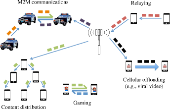
In academia, D2D communication was first proposed in [3] to enable multihop relays in cellular networks. Later the works in [73, 74, 75, 76, 77] investigated the potential of D2D communications for improving spectral efficiency of cellular networks. Soon after, other potential D2D use-cases were introduced in the literature such as multicasting [78, 79], peer-to-peer communication [80], video dissemination [81, 82, 83, 74], machine-to-machine communication [84], cellular offloading [85], and so on. The most popular use-cases of D2D communications are shown in Figure 2.2. The first attempt to implement D2D communications in a cellular network was made by Qualcomm’s FlashLinQ [4] which is a PHY/MAC network architecture for D2D communications underlaying cellular networks. FlashLinQ takes advantage of OFDM/OFDMA technologies and distributed scheduling to create an efficient method for timing synchronization, peer discovery, and link management in D2D-enabled cellular networks. In addition to academia and telecommunication companies, 3GPP is also investigating D2D communications as Proximity-based Services (ProSe). In particular, the feasibility of ProSe and its use-cases in LTE are studied in [5] and the required architectural enhancements to accommodate such use-cases are investigated in [6]. A brief overview of standardization activities and the fundamentals of 3GPP ProSe can be found in [86].
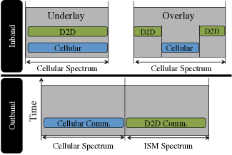
The majority of the literature on D2D communications proposes to use the cellular spectrum for both D2D and cellular communications (i.e., underlay inband D2D). These works usually study the problem of interference mitigation between D2D and cellular communication [87, 88, 89, 90, 77, 91, 92, 93, 94]. In order to avoid the aforementioned interference issue, some propose to dedicate part of the cellular resources only to D2D communications (i.e., overlay inband D2D). Here resource allocation gains utmost importance so that dedicated cellular resources be not wasted [95]. Other researchers propose to adopt outband rather than inband D2D communications in cellular networks so that the precious cellular spectrum be not affected by D2D communications. In outband communications, the coordination between radio interfaces is either controlled by the BS (i.e, controlled) or the users themselves (i.e., autonomous). Outband D2D communications face a few challenges in coordinating the communication over two different bands because usually D2D communications happen on a second radio interface (e.g., WiFi Direct [96] and Bluetooth [97]). The studies on outband D2D investigate issues such as power consumption [17, 12, 9, 11, 98] and inter-technology architectural design. Figure 2.3 graphically depicts the difference among underlay inband, overlay inband, and outband communications.
2.2.1 Taxonomy
In this section, we categorize the available literature on D2D communication in cellular networks based on the spectrum in which D2D communications occur. In the following, we provide a formal definition for each category and sub-category. Next, we provide a quick overview of the advantages and disadvantages of each D2D method.
Inband D2D: The literature under this category, which contains the majority of the available work, proposes to use the cellular spectrum for both D2D and cellular links. The motivation for choosing inband communication is usually the high control over cellular (i.e., licensed) spectrum. Some researchers (see, e.g., [99, 75]) consider that the interference in the unlicensed spectrum is uncontrollable which imposes constraints for QoS provisioning. Inband communication can be further divided into underlay and overlay categories. In underlay D2D communication, cellular and D2D communications share the same radio resources. In contrast, D2D links in overlay communication are given dedicated cellular resources. Inband D2D can improve the spectrum efficiency of cellular networks by reusing spectrum resources (i.e., underlay) or allocating dedicated cellular resources to D2D users that accommodates direct connection between the transmitter and the receiver (i.e., overlay). The key disadvantage of inband D2D is the interference caused by D2D users to cellular communications and vice versa. This interference can be mitigated by introducing high complexity resource allocation methods, which increase the computational overhead of the BS or D2D users.
Outband D2D: Here the D2D links exploit unlicensed spectrum. The motivation behind using outband D2D communication is to eliminate the interference issue between D2D and cellular links. Using unlicensed spectrum requires an extra interface and usually adopts other wireless technologies such as WiFi Direct [96], ZigBee [100] or Bluetooth [97]. Some of the work on outband D2D (see, e.g., [81, 82, 12, 17]) suggest to give the control of the second interface/technology to the cellular network (i.e., controlled). In contrast, others (see, e.g., [98]) propose to keep cellular communications controlled and leave the D2D communications to the users (i.e., autonomous). Outband D2D uses unlicensed spectrum which makes the interference issue between D2D and cellular users irrelevant. On the other hand, outband D2D may suffer from the uncontrolled nature of unlicensed spectrum. It should be noted that only cellular devices with two wireless interfaces (e.g., LTE and WiFi) can use outband D2D, and thus users can have simultaneous D2D and cellular communications.
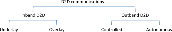
Figure 2.4 illustrates the taxonomy introduced for D2D communications in cellular networks. In the following sections, we review the related literature based on this taxonomy.
2.2.2 Underlay Inband D2D
Early works on D2D in cellular networks propose to reuse cellular spectrum for D2D communications. To date, the majority of available literature is also dedicated to inband D2D, especially D2D communications underlaying cellular networks. In this section, we review the articles that employ underlaying D2D to improve the performance of cellular networks, in terms of spectrum efficiency, energy efficiency, cellular coverage, and other performance targets.
Zhang et al. [91] propose a graph-based resource allocation method for cellular networks with underlay D2D communications. They mathematically formulate the optimal resource allocation as a nonlinear problem which is NP-Hard. The authors propose a suboptimal graph-based approach which accounts for interference and capacity of the network. In their proposed graph, each vertex represents a link (D2D or cellular) and each edge connecting two vertices shows the potential interference between the two links. The simulation results show that the graph-based approach performs close to the throughput-optimal resource allocation.
Janis et al. address a similar solution in [92], where the D2D users also measure the signal power of cellular users and inform the BS of these values. The BS then avoids allocating the same frequency-time slot to the cellular and D2D users which have strong interference with each other, which is different from [89]. The proposed scheme of [92] minimizes the maximum received power at D2D pairs from cellular users. The authors first show via numerical results that D2D communications with random resource allocation can increase the mean cell capacity over a conventional cellular system by . Next, they show that their proposed interference-aware resource allocation scheme achieves higher capacity gain than the random resource allocation strategy.
The work in [93] proposes a new interference management in which the interference is not controlled by limiting D2D transmission power as in the conventional D2D interference management mechanisms. The proposed scheme defines an interference limited area in which no cellular users can occupy the same resources as the D2D pair. Therefore, the interference between the D2D pair and cellular users is avoided. The disadvantage of this approach is reducing multi-user diversity because the physical separation limits the scheduling alternatives for the BS. However, numerical simulations prove that the capacity loss due to multi-user diversity reduction is negligible compared to the gain achieved by their proposal. In fact, this proposal provides a gain of over conventional interference management schemes.
The authors of [101] propose an algorithm for power allocation and mode selection in D2D communication underlaying cellular networks. The algorithm measures the power efficiency, which is a function of transmission rate and power consumption, of the users in different modes (cellular and D2D). After computing the power efficiency, each device uses the mode in which it achieves higher power efficiency. The drawback of this algorithm is that the controller should perform an exhaustive search for all possible combinations of modes for all devices. The authors benchmark their algorithm against the scheme of [102] in which two users communicate over D2D link only if their pathloss is lower than the pathlosses between each user and the BS. The simulation results indicate that their algorithm achieves up to gain over the scheme proposed in [102].
The authors of [103] consider the mode selection and resource allocation in D2D communications underlay cellular networks, where several pairs of D2D links co-exist with several cellular users. They formulate the problem of maximizing the system throughput with minimum data rate requirements, and use the particle swarm optimization [104] method to obtain the solutions. The simulation results show that the proposed method has throughput gain over the orthogonal resource sharing scheme (i.e., overlay D2D which will be explained later), where the achievable gain varies with the distance of D2D users. Simulation results also show that this method can improve the system performance under the constraint of minimum data rate of users.
The authors of [105] consider the scheduling and mode selection problem for D2D in OFDMA networks. They assume that the system time is slotted and each channel is divided into sub-channels. They formulate the problem of maximizing the mean sum-rate of the system with QoS satisfaction as a stochastic optimization problem, and use the stochastic sub-gradient algorithm to solve it. From the solution, they design a sub-channel opportunistic scheduling algorithm that takes into account the CSI of D2D and cellular links as well as the QoS requirement of each D2D user. The numerical results show that the mean sum-rate can be improved by up to . This gain increases when the average D2D pair distance reduces. Moreover, with the D2D communication, the fairness among users can be achieved with the QoS requirement specified for each user.
Finally, a summary of the works on underlay D2D communications in cellular networks is provided in Table 2.3, in terms of metrics, use-cases, analytical tools, evaluation method, scope, and achieved performances.
Proposal Analytical tools Platform Direction Use-case Evaluation Achieved performance Improving spectrum efficiency [77, 89] [92, 73, 93, 106] [107, 74, 108, 76] [109, 95, 110, 111] -Chen-Stein method -Zipf distribution -Integer/linear programming -Mixed integer nonlinear programming -Convex optimization -Bipartite Matching -Kuhn-Munkres algorithm -Han-Kobayashi -Newton’s method -Lagrangian multipliers -Graph theory -Auction algorithm -Particle swarm optimization -WiMax -CDMA -LTE -LTE-A -Uplink -Downlink -Uplink/ downlink -Content distribution -File sharing -Video/file exchange -Numerical simulation -System-level simulation -System throughput can be improved from to compared with conventional cellular networks under common scenarios -Throughput can be improved up to when D2D users are far away from the BS -Number of admitted D2D users can be increased up to Improving power efficiency [112, 101] [113, 114] -Heuristic algorithms -Exhaustive search -Linear programming -LTE -LTE-A -OFDMA -Uplink -Downlink -Uplink/ downlink -System-level simulation -Power efficiency can be improved from to compared with conventional cellular networks Improving performance with QoS/power constraints [115, 103] [105, 116, 114, 117] -Heuristic algorithms -Bipartite Matching -Kuhn-Munkres algorithm -LTE -LTE-A -Uplink -Downlink -VOIP/FTP -Numerical simulation -System-level simulation -From to throughput gain with QoS constraint -From to sum-rate gain with QoS/power constraint Improving fairness [88] -Auction algorithm -Downlink -System-level simulation -A fairness index around Improving cellular coverage [118] -LTE -LTE-A -Uplink/ downlink -Numerical simulation -Throughput of cell edge users can be improved up to -Cell coverage is also enlarged up to Supporting setup of D2D [119] -Protocol -LTE-A -Uplink/ downlink -D2D link setup Improving reliability [120, 121] -Numerical simulation -Outage probability reduces by Increasing the number of concurrent D2D links[122] -Mixed-integer nonlinear programming -Hungarian algorithm -Heuristic algorithm -LTE -Uplink -System-level simulation -Number of admitted D2D links is increased up to compared to random D2D link allocation Offloading traffic [85] -Offloading traffic -System-level simulation Improving performance of multicast [78, 123] -LTE -LTE-A -Uplink/ downlink -Multicast -Numerical simulation -System-level simulation -Frame loss ratio of feedback is reduced by
2.2.3 Overlay Inband D2D
Different from the works reviewed in the previous subsection, the authors of [124, 83, 79] propose to allocate dedicated resources for D2D communications. This approach eliminates the concerns for interference from D2D communications on cellular transmissions, but reduces the amount of achievable resources for cellular communications.
In [124], Fodor et al. elaborate on the challenges of D2D communications in cellular networks and suggest to control D2D communications from the cellular network. They claim that network assistance can solve the inefficiencies of D2D communications in terms of service and peer discovery, mode selection, channel quality estimation, and power control. In a conventional peer and service discovery method, D2D users should send beacons in short intervals and monitor multiple channels which is very energy consuming. However, this process can become more energy efficient if the BS regulates the beaconing channel and assists D2D users so that they do not have to follow the power consuming random sensing procedure. BS assistance also improves the scheduling and power control which reduces the D2D interference. The authors use simple Monte-Carlo simulation to evaluate the performance of D2D communications. The results show that D2D can increase the energy efficiency from bps/Hz/mW to bps/Hz/mW in the best case scenario where the distance between D2D users is m.
The authors of [83] propose the incremental relay mode for D2D communications in cellular networks. In the incremental relay scheme, D2D transmitters multicast to both the D2D receiver and BS. In case the D2D transmission fails, the BS retransmits the multicast message to the D2D receiver. The authors claim that the incremental relay scheme improves the system throughput because the BS receives a copy of the D2D message which is retransmitted in case of failure. Therefore, this scheme reduces the outage probability of D2D transmissions. Although the incremental relay mode consumes part of the downlink resources for retransmission, the numerical simulation results show that this scheme still improves the cell throughput by in comparison to underlay mode.
In [79], D2D communication is used to improve the performance of multicast transmission in cellular networks. Due to wireless channel diversity, some of the multicast group members (i.e., cluster) may not receive the data correctly. The authors propose to use D2D communications inside the clusters to enhance the multicast performance. Specifically, after every multicast transmission, some of the members which manage to decode the message will retransmit it to those which could not decode the message. Unlike the prior work in [125] and [126] where there is only one predefined retransmitter, the number of retransmitters in [79] changes dynamically to maximize the spectral efficiency. The authors show via numerical simulations that their proposed algorithm consumes less spectrum resources in comparison to the scenario with only one retransmitter.
Proposal Analytical tools Platform Direction Use-case Evaluation Achieved performance Increasing energy efficiency [124] -LTE -Uplink -Numerical simulation -Energy efficiency can be increased from 0.8 bps/Hz/mW to 20 bps/Hz/mW Improving spectrum efficiency [83] -Convex Optimization -Uplink -Numerical simulation -Cell throughput is improved by over underlay mode Improving performance of multicast [79] -Downlink -Video transmission -Numerical simulation - gain in bandwidth compared to the method using only one retransmitter
2.2.4 Outband D2D
In this section, we review the articles in which D2D communications occur on a frequency band that is not overlapping with the cellular spectrum. Outband D2D is advantageous because there is no interference issue between D2D and cellular communications. Outband D2D communications can be managed by the cellular network (i.e., controlled) or it can operate on its own (i.e., autonomous).
2.2.4.1 Controlled
In works that fall under this category, the authors propose to use the cellular network advanced management features to control D2D communications to improve the efficiency and reliability of D2D communications. They aim to improve system performance in terms of throughput, power efficiency, multicast, and so on.
The authors of [127] propose to use Industrial, Scientific and Medical (ISM) band for D2D communications in LTE. They state that simultaneous channel contention from both D2D and WLAN users can dramatically reduce the network performance. Therefore, they propose to group D2D users based on their QoS requirements and allow only one user per group to contend for the WiFi channel. The channel sensing between groups is also managed in a way that the groups do not sense the same channel at the same time. They show via simulation that their approach increases the D2D throughput up to in comparison to the scenario in which users contend for the channel individually.
Golrezaei et al. [81, 82] point out the similarities among video content requests of cellular users. They propose to cache the popular video files (i.e., viral videos) on smartphones and exploit D2D communications for viral video transmissions in cellular networks. They partition each cell into clusters (smaller cells) and cache the non-overlapping contents within the same cluster. When a user sends a request to the BS for a certain content, the BS checks the availability of the file in the cluster. If the content is not cached in the cluster, the user receives the content directly from the BS. If the content is locally available, the user receives the file from its neighbor in the cluster over the unlicensed band (e.g., via WiFi). The authors claim that their proposal improves the video throughput by one or two orders of magnitude.
The authors of [128] propose a method to improve video transmission in cellular networks using D2D communications. This method exploits the property of asynchronous content reuse by combining D2D communications and video caching on mobile devices. Their objective is to maximize per-user throughput constrained to the outage probability (i.e., the probability that a user’s demand is unserved). They assume devices communicate with each other with a fixed data rate and there is no power control over the D2D link. Through simulations, the authors show that their proposed method outperforms the schemes with conventional unicast video transmission as well as the coded broadcasting [129]. The results show that their proposed method can achieve at least and throughput gain over the conventional and coded broadcasting methods, respectively, when the outage probability is less than .
Wang et al. [130] propose a BS-drIven Traffic Spreading (BITS) algorithm to exploit both the cellular and D2D links. BITS leverages devices’ instantaneous channel conditions and queue backlogs to maximize the BS’s scheduling options and hence increases the opportunistic gain. The authors model the BITS policy with the objective to maximize delay-sensitive utility under an energy constraint. They develop an online scheduling algorithm using stochastic Lyapunov optimization and study its properties. Through simulations, they show that under BITS the utility can be improved greatly and the average packet transfer delay can be reduced by up to . The authors also evaluate BITS using realistic video traces. The results show that BITS can improve the average peak signal-to-noise ratio of the received video by up to dB and the frame loss ratio can be reduced by up to .
2.2.4.2 Autonomous
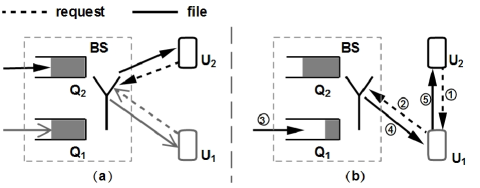
Autonomous D2D communications are usually motivated by reducing the overhead of cellular networks. It does not require any changes at the BS and can be deployed easily. Currently, there are very few works in this category. Wang et al. [98] propose a downlink BS-transparent dispatching policy where users spread traffic requests among each other to balance their backlogs at the BS, as shown in Figure 2.5. They assume that users’ traffic is dynamic, i.e., the BS does not always have traffic to send to all the users at any time. They illustrate the dispatching policy by considering a scenario with two users, and being served by the BS. The queues and depict the numbers of files at user’s BS queues. In Figure 2.5(a), since the queues at the BS are balanced, the dispatchers at each user would detect that traffic spreading is not beneficial. Thus, users send their new requests to the BS directly. In Figure 2.5(b), there are more files in than . The dispatcher of would detect that traffic spreading is beneficial, because in the near future would be empty and thus the opportunistic scheduling gain is lost. Therefore, asks to forward its new file requests to the BS. After receiving the corresponding files from the BS, forwards them to . This dispatching policy is user-initiated (i.e., it does not require any changes at the BS) and works on a per-file basis. This policy exploits both the time-varying wireless channel and users’ queueing dynamics at the BS in order to reduce average file transfer delays seen by the users. The users perceive their channel conditions to the BS (i.e., cellular channel conditions) and share them among each other. The authors formulate the problem of determining the optimal file dispatching policy under a specified tradeoff between delay performance and energy consumption as a Markov decision problem. Next, they study the properties of the corresponding optimal policy in a two-user scenario. A heuristic algorithm is proposed which reduces the complexity in large systems by aggregating the users. The simulation results demonstrate that the file transfer delays can be reduced by up to using the proposed methodology. In addition, their proposal consumes less power than performance-centric algorithms while achieving significant gains (up to ).
Proposal Analytical tools Platform Direction Use-case Evaluation Achieved performance Improving throughput of video distribution [81, 82] -Game theory -Chen-Stein method -Downlink -Content distribution -Numerical simulation -Video throughput is improved by up to two orders of magnitude Reducing channel sensing overhead [127] -LTE -Relaying -System-level simulation -Throughput is improved by up to Improving throughput, energy efficiency, and fairness [12, 17, 131] -Game theory -LTE -CDMA -Downlink -Relaying -Video transmission -Numerical simulation -Throughput and energy efficiency are improved by and over classical Round Robin scheduler, respectively Designing a protocol for outband D2D communications [11] -LTE -Downlink -Uplink -Relaying -System-level simulation - delay improvement compared to Round Robin scheduler Improving video transmission [128] -LTE -Downlink -Video transmission -System-level simulation -Throughput is improved by and over conventional and coded broadcasting methods, respectively Improving delay sensitive utility [130] -Lyapunov optimization -LTE -Downlink -Online gaming -Live video -System-level simulation -Average packet delay is reduced by up to -Utility can be improved greatly Reducing average file transfer delay [98] -Dynamic programming -Heuristic algorithm -Distributed algorithm -Queueing theory -LTE -Downlink -Web browsing -HTTP live streaming -System-level simulation -Average file transfer delay is reduced by up to compared to methods without traffic spreading
2.2.5 Discussions
So far we have reviewed the available literature on D2D communications in cellular networks. In this section, we will shed light on some important factors such as common assumptions, scope of the works, and common techniques.
2.2.5.1 Common Assumptions
Most of the papers in the literature assume the BS is aware of the instantaneous CSI of cellular and/or D2D links, e.g., [93, 112, 115, 107, 114, 103, 122]. This assumption is essential because their proposed solutions need the BS’s participation to make scheduling decisions for cellular and D2D users. Alternatively, when the D2D users decide on the their transmission slots, the common assumption is that D2D users are aware of the cellular and D2D links. On the other hand, there are also papers such as [87] and [98] that assume the BS or D2D users are only aware of the statistical CSI of the links. With this assumption, the large overhead for reporting instantaneous CSI can be avoided. To mitigate possible interference from D2D transmissions to cellular transmissions, [73] assumes that D2D users are aware of minimum interference threshold of cellular users. With the latter assumptions, the D2D users can opportunistically choose the transmission slots in which they do not interfere with the cellular users.
The proposals which involve in clustering users commonly assume that the cluster are far enough so that there is no or negligible interference among different clusters, e.g., [78, 132, 17, 12]. This assumption may not hold in populated areas or dense deployments. A very interesting observation from the reviewed literature is that the majority of articles assume that the BS or D2D users always have traffic to send, therefore they use throughput as a common metric. However, the authors of [98, 130] consider a scenario with dynamic traffic load and evaluate the average file transfer delay and delay-sensitive utility under their proposed traffic spreading mechanism, respectively. Since the latter assumption is more realistic, it would be interesting to see the performance of the aforementioned works under dynamic traffic flows.
2.2.5.2 Inband or Outband?
Majority of the papers propose to reuse the cellular resources for D2D communications (i.e., inband) [73, 74, 75, 108, 133]. However, outband communications is attracting more and more attention in the past few years [12, 17, 98, 130, 134]. Before comparing the two approaches, we summarize the advantages and disadvantages of each approach.
Inband Outband Underlay Overlay Controlled Autonomous Interference between D2D and cellular users Requires dedicated resources for D2D users Controlled interference environment Simultaneous D2D and cellular transmission Requires inter-platform coordination Requires devices with more than one radio interface Introduces extra complexity to scheduler
Inband. Inband D2D is advantageous in the sense that: underlay D2D increases the spectral efficiency of cellular spectrum by exploiting the spatial diversity; any cellular device is capable of using inband D2D communications (the cellular interface usually does not support outband frequencies); and QoS management is easy because the cellular spectrum can be fully controlled by the BS. The disadvantages of inband D2D communications are: cellular resources might be wasted in overlay D2D; the interference management among D2D and cellular transmissions in underlay is very challenging; power control and interference management solutions usually resort to high complexity resource allocation methods; and a user cannot have simultaneous cellular and D2D transmissions. It appears that underlay D2D communications is more popular than overlay. The authors who propose to use overlay D2D usually try to avoid the interference issue of underlay [124, 83, 79]. However, allocating dedicated spectrum resources to D2D users is not as efficient as underlay in terms of spectral efficiency. We believe that the popularity of underlay D2D is due to its higher spectral efficiency.
Outband. This type of D2D communications has merits such as: there is no interference between cellular and D2D users; there is no need for dedicating cellular resources to D2D spectrum like overlay inband D2D; the resource allocation becomes easier because the scheduler does not require to take the frequency, time, and location of the users into account; and simultaneous D2D and cellular communications is feasible. Nevertheless outband D2D has some disadvantages which are: the interference in unlicensed spectrum is not under the control of the BS; only cellular devices with two radio interfaces (e.g., LTE and WiFi) can use outband D2D communications; the efficient power management between two wireless interfaces is crucial, otherwise the power consumption of the device can increase; and packets (at least the headers) need to be decoded and encoded because the protocols employed by different radio interfaces are not the same.
Although the literature on inband D2D is wider than that of outband, it seems that researchers have started to explore the advantages of outband D2D and they are considering it as a viable alternative to inband D2D. We believe that with the evolutionary integration of smartphones in phone market, the majority of mobile devices will be equipped with more than one wireless interface which makes it possible to implement outband D2D schemes. Moreover, the standards such as 802.21 [135] are looking into handover to and from different platforms (e.g., WiMAX and LTE) which could significantly reduce the complexity of coordination between different wireless interfaces in outband D2D. Table 2.6 summarizes the above mentioned merits and disadvantages.
2.2.5.3 Maturity of D2D in Cellular Networks
We believe D2D communications in cellular networks is a relatively young topic and there is a lot to be done/explored in this field. We support this belief by looking into the analytical techniques and evaluation methods which are used in the available literature.
Analytical techniques. In comparison to other fields such as opportunistic scheduling [1], the number of techniques used in the literature and their popularity is very low. The majority of the literature only proposes ideas, architectures, or simple heuristic algorithms. Some of the papers formulate their objectives as optimization problems but leave them unsolved due to NP-hardness. Therefore, we believe there is room for investigating optimal solutions for interference coordination, power management, and mode selection. Table 2.7 summarizes the mathematical techniques used in the D2D related literature.
| Tools | Related literature |
|---|---|
| Discrete Time Markov chain | [99] |
| Merge and split algorithm | [99] |
| Distributed algorithms | [98, 99, 122] |
| Coalitional game theory | [99] |
| Poisson point process | [136] |
| Queueing theory | [98] |
| Alzer’s inequality | [136] |
| Fubini’s theorem | [136] |
| Laplace transform | [136, 137] |
| Slivnyak’s theorem | [136] |
| Heuristic algorithm | [98, 112, 122] |
| Convex Optimization | [83, 110] |
| Chen-Stein Method | [82] |
| Maximum Weight Bipartite Matching | [115] |
| Kuhn-Munkres algorithm | [115] |
| Han-Kobayashi | [107] |
| Jensen’s Inequality | [137] |
| Mixed integer nonlinear programming | [109] |
| Integer programming | [116] |
| Linear programming | [113, 116] |
| Nonlinear programming | [122] |
| Dynamic programming | [98] |
| Newton’s method | [116] |
| Lagrangian multipliers | [116] |
| Graph theory | [91] |
| Auction algorithms | [88, 111] |
| Exhaustive search | [101] |
| Geometrical probability | [121] |
| Evolution theory | [132] |
| Particle swarm optimization | [103] |
| Sub-gradient algorithm | [105] |
| Hungarian algorithm | [122] |
| Lyapunov optimization | [130] |
Evaluation method. Another metric for maturity of a field is the evaluation method. The more realistic the evaluation method, the more mature the study of that field. Table 2.8 shows different evaluation methods used in the literature. As we can see, majority of the papers use numerical evaluation and some use simple home-grown simulators. There is no paper using experimental evaluation. This is mainly due to the fact that experimental testbeds for cellular network are extremely costly and do not have support for D2D yet. The literature rarely uses popular network simulators such as NS3 [138], OPNET [139], Omnet++ [140]. In turn, currently available network simulators do not support D2D communications.
| Evaluation method | Related literature |
|---|---|
| Numerical simulation | [93, 136, 78, 81, 73, 74, 115, 107] |
| [137, 124, 106, 116, 92, 79, 84, 108] | |
| [132, 95, 117, 105, 82, 91, 87, 114] | |
| [87, 120, 111, 103, 118, 111, 103, 118] | |
| System-level simulation | [109, 113, 127, 77, 111, 110, 75, 92] |
| [112, 141, 99, 128, 101, 85, 123, 142] | |
| [143, 98, 122, 130] | |
| Experiment | No experimental study |
2.2.5.4 How Far is D2D from a Real World Implementation?
Although D2D communication is not mature yet, it is already being studied in the 3GPP standardization body [5, 6]. 3GPP recently decided that the focus of D2D in LTE would be on public safety networks [86]. Moreover, Qualcomm has shown interest in this technology and they also built a prototype for D2D communications in cellular network which can be used in different scenarios such as social networking, content sharing, and so on [144]. This confirms that D2D communications are not only a new research topic in academia, but also that there is interest in such a technology in the industry. There are various obstacles to implement D2D in cellular networks. For example, the operators are used to having control of their spectrum and the way it is used. As a result, a successful D2D implementation should allow D2D communications in a manner that operators are not stripped off their power to control their network. Moreover, there are physical challenges such as suitable modulation format and CSI acquisition which should be addressed efficiently. Therefore, we believe that thanks to ProSe, D2D communications will become an essential part of cellular communications in the next few years.
2.2.6 Future Trends and Thesis Contribution
Although D2D communication triggered a lot of attention and interest in academia, industry, and standardization bodies, it is not going to be integrated into the current communication infrastructure until the implementation challenges are resolved. Here, we explain some of the major challenges faced by D2D communications.
Interference management. Under inband D2D communications, UEs can reuse uplink/downlink resources in the same cell. Therefore, it is important to design the D2D mechanism in a manner that D2D users do not disrupt the cellular services. Interference management is usually addressed by power and resource allocation schemes, although the characteristics of D2D interference are not well understood yet.
Power allocation. In inband D2D, the transmission power should be properly regulated so that the D2D transmitter does not interfere with cellular UE communications while maintaining the minimum SINR requirement of the D2D receiver. In outband D2D, the interference between D2D and cellular user is not of concern. Therefore, power allocation may seem irrelevant in outband D2D. However, with increased occupancy of ISM bands, efficient power allocation becomes crucial for avoiding congestion, collision issues, and inter-system interference.
Resource allocation. This is another important aspect of D2D communications specially for inband D2D. Interference can be efficiently managed if the D2D users communicate over resource blocks that are not used by the nearby interfering cellular UEs. Resource allocation for outband D2D simply consists in avoiding ISM bands which are currently used by other D2D users, WiFi hotspots, etc.
Modulation format. This is one of the challenges which is rarely addressed by researchers. The existing LTE UEs use an OFDMA receiver in downlink and a Single Carrier-FDMA (SC-FDMA) for uplink transmission. Thus, for using downlink (resp. uplink) resources, the D2D UE should be equipped with OFDMA transmitter (resp. SC-FDMA receiver) [86].
Channel measurement. Accurate channel information is indispensable to perform efficient interference management, power allocation, and resource allocation. Conventional cellular systems only need the downlink channel information from UEs and the uplink channel information is readily computed at the base station. Unfortunately, D2D communications require information on the channel gain between D2D pairs, the channel gain between D2D transmitter and cellular UE, and the channel gain between cellular transmitter and D2D receiver. The exchange of such extra channel information can become an intolerable overhead to the system if the system needs instantaneous CSI feedback. The trade-off between accuracy of CSI and its resulting overhead is to be further investigated.
Energy consumption. D2D communications can potentially improve the energy efficiency of the UE. However, this highly depends on the protocol designed for device discovery and D2D communications. For example, if the protocol forces the UE to wake up very often to listen for pairing requests or to transmit the discovery messages frequently, the battery life of the UE may significantly reduces. The trade-off between UE’s power consumption and discovery speed of the UEs should be better studied.
Hybrid Automatic Repeat Request (HARQ). Considering the complexity of interference management in D2D communications, HARQ appears to be a viable technique to increase the robustness. HARQ can be sent either directly (i.e., from the D2D receiver to the transmitter) or indirectly (i.e., from the D2D receiver to the eNB, and from the eNB to the D2D transmitter) [86]. The direct mode poses less overhead to the eNB in comparison to indirect mode. Moreover, benefits from the ACK/NACK messages arrive to the transmitter with shorter delay.
In this thesis, we contributed to several open problems in D2D communications. We investigated energy consumption of the mobile devices participating in opportunistic D2D clustering techniques. Moreover, we explored the implementation feasibility of D2D clustering from a protocol point of view in LTE-A and WiFi Direct technologies. Last but not least, we prototyped the first experimental testbed for outband D2D communications.
D2D-Assisted Clustering
Chapter 3 Theoretical Analysis
3.1 Introduction
In 3GPP’s definition [145], D2D is a flexible paradigm that is open to use cellular platforms (i.e., inband D2D) or 802.11-like platforms (i.e., outband D2D) for direct communication [2]. Flexibility also extends to a variety of use-cases such as public safety, content distribution, advertisement, and network offloading using 802.11 protocols. In particular, network offloading based on D2D has been studied in terms of grouping/clustering techniques [146, 123, 79, 147, 12, 11]. The analytical and simulation results indicate that clustering cellular users to relay traffic to each other leads to lower signaling overhead, higher spectral efficiency, and better energy efficiency. However, while the literature on inband D2D communications is abundant [2], outband D2D has been less studied. This is mostly due to the skepticism of the research community towards acceptance of 802.11 as a possible platform for network-controlled D2D communications in 3GPP ProSe. Nevertheless, the slow standardization process of inband D2D is driving industry to look at outband D2D as a more tangible implementation option.
In this chapter, we investigate an outband D2D clustering scheme that opportunistically leverages the flexibility of D2D communications in cellular networks for improving network performance under the control of the cellular operator. As shown in Figure 3.1, in our vision, cellular devices can form stable clusters using WiFi Direct [96] and the cluster member with the highest channel quality acts as relay for other cluster members. The opportunism in our proposal is twofold: first, the relay node changes over time within the same cluster, to follow signal quality variations; second, the throughput gain obtained due to clustering is shared within the cluster according to the contribution of each member. In the proposal detailed in this article, we aim at maximizing the efficiency of cellular resource utilization, although we also account for the impact of per-user performance in general and for cluster formation policies in particular, which we analyze by using game theory.
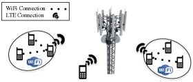
3.2 System Model
This section details the architecture of our proposed D2D-clusters, the model assumptions, and the throughput and power model of the proposed scheme. In our proposed scheme, mobiles can form clusters and receive downlink traffic through the cluster head, i.e., the node enabled to exchange data with the base station (see Figure 3.1). Note that each node is a potential candidate to act as cluster head, and cluster heads are selected on a per-frame basis. A cluster consists of several mobiles that form a WiFi Direct group and all intra-cluster communications take place over the WiFi Direct network. Since the base station is aware of and controls clustering decisions, whenever a packet is destined to a cluster member, the base station simply sends it to the cluster head. This maximizes the throughput at that scheduling epoch. Thereby, the base station schedules entire clusters as if they were regular users. From a modeling perspective, a cluster can be considered as a user whose SNR is the highest of the SNR values of cluster members. As for intra-cluster resource sharing, unless otherwise specified, we assume that the extra throughput gained from clustering is equally distributed among users.
3.2.1 Assumptions
We model downlink transmissions in a single LTE-like in FDD mode. There are mobile users in the cell. Since we are interested in network capacity and fairness under heavy load conditions, we study the case of fully backlogged downlink flows in the analysis. Nevertheless, our analysis can be easily applied for uplink communications as well. The number of OFDM symbols in downlink is denoted by , and we assume that the D2D link (i.e., WiFi Direct) does not become a bottleneck in the data flow. In fact, considering the short-range nature of D2D communications, the available WiFi capacity exceeds per-cluster achievable throughput over LTE.111There are at least 26 non-overlapping WiFi channels in 2.4GHz and 5GHz band with per-channel nominal capacity of Mbps, which is much more than the Mbps achievable in a SISO LTE-A system or the Mbps of a MIMO system. It is also assumed that all mobiles belong to the same operator. The downlink channel of mobile node is characterized by stationary Rayleigh fading. Therefore, the SNR can be described as a r.v. with average SNR , so that the Cumulative Distribution Function (CDF) of the SNR has the following expression:
| (3.1) |
We assume that user channels are independently distributed but not identically, and the CSI is available at the base station. Transmissions occur at different rates according to available Modulation and Coding Schemes. We assume that the MCS for user is a function of the instantaneous SNR, i.e.:
Hence, the probability that scheduled transmissions to user are encoded with the th MCS is:
| (3.2) |
3.2.2 Throughput Model for D2D-Clusters
In the following, the throughput of D2D clusters is modeled under two simple opportunistic cluster head selection (cluster scheduling) schemes. Opportunistic schemes commonly result in unfairness which is often resolved at the cost of increased complexity. However, the practicality of such schemes is often doubted due to high computation overhead imposed to the base station. We intentionally opt for opportunistic schemes with low complexity to pave the way towards a practical proposal. We choose to resolve the unfairness issue by leveraging cooperative nature of D2D clusters instead of increasing the complexity. We consider the case in which the base station schedules clusters instead of normal users. This means that the base station decides which cluster has to be served, and then transmissions are managed by the current cluster head. Defining as the SNR of cluster (), we have: where is user , . The CDF of can be readily computed considering that the random variables are all independent:
| (3.3) |
The adopted MCS, for each transmission, only depends on the instantaneous SNR of the best channel in the scheduled cluster, i.e., it only depends on at the scheduling epoch:
| (3.4) |
Cluster Weighted Round Robin (CL(WRR)). This scheme chooses the cluster member with the best channel quality as the cluster head and it schedules the cluster heads in a Weighted Round Robin (WRR) fashion. Hence, each cluster receives a portion of airtime which corresponds to its weight , . In this dissertation, the weight of is calculated using , where denotes the number of cluster members of . In other words, each cluster receives an amount of airtime which is proportional to its size.
In such a system, the per-cluster scheduling probability is exactly , while the average symbol rate only depends on the selected MCS. Since available frame resources are allocated in a WRR manner, the average cluster and the per-user throughput are given by the Propositions 1 and 2, whose proofs are immediate so we omit them.
Proposition 1.
Under CL(WRR), the average throughput received by cluster is
| (3.5) |
Proposition 2.
Under CL(WRR), the average throughput of user can be expressed as
| (3.6) |
The following proposition gives the probability that a user is scheduled.
Proposition 3.
The proof of Proposition 3 is reported in Appendix A. Note that, under Rayleigh fading assumptions, the conditional probability is simply given by the following formula:
| (3.8) |
Cluster Max Rate (CL(MR)). Here, the cluster heads are scheduled in a pure Max Rate (MR) fashion [25]. In this scheme, each frame resources are allotted to the cluster whose cluster head is experiencing the best SNR in the system. Propositions 4 and 5 express the cluster throughput and average per-user throughput achieved using CL(MR).
Proposition 4.
The proof of Proposition 4 is reported in Appendix A.
Proposition 5.
3.2.3 Power Consumption Analysis
We derive the power consumption of mobiles from the empirical power models proposed for LTE and WiFi in [148] and [149]. Those studies show: how to include the baseline power required to keep the interface up and running; and how to account for the variability of power consumption with transmission rate, and differentiate transmission from reception. However, unlike the existing models, we account for practical details such as power consumption of the UE in active and idle periods, and the difference between transmission and reception power.
Before further elaboration on power model of D2D-clusters, we want to differentiate between the average throughput and the data rate of a user. is the user-application local data received by a user directly via LTE or via WiFi relay, and it is computed via (3.6) and (3.10). is the amount of data received by a user and it includes non-local traffic to be relayed.
3.2.3.1 Power Saving in LTE and WiFi
LTE allows the UE to switch to idle mode in order to save energy. The mechanisms that handle idle periods are discontinuous reception and discontinuous transmission [150]. In WiFi, users can turn off the wireless interface during idle periods and only switch it on to receive beacons [151]. In both LTE and WiFi, interfaces in power saving mode periodically wake up to transmit/receive control information even if there is no data traffic to handle. However, it has been shown that the periodic wake-up of power saving mechanisms in LTE and WiFi impacts at most of the idle time [148]. Therefore, for simplicity, we ignore the periodic wake-up operation. We assume that wireless interfaces instantaneously switch to power saving mode in absence of packets to be tranceived. With the arrival of a new packet in the transmission queue, the interfaces switch back to active mode instantly.
3.2.3.2 LTE Consumption
Based on [148], the downlink power consumption of user in the cellular network consists of the sum of a baseline power and a term which is proportional to the transmission rate of the device. As mentioned earlier, we extend the existing model to account for active/idle periods. The probability that the LTE interface is in active mode is equivalent to the probability of being the cluster head, see Eqs. (3.7) and (3.11). Therefore, the LTE interface power consumption of a device can be expressed as follows:
| (3.12) |
where, and are the baseline powers in active and idle mode, respectively; is the power consumption per Mbps in uplink, and is the average data rate transmitted by user over the LTE interface. The value of is computed using the following two propositions.
Proposition 7.
Proposition 8.
3.2.3.3 WiFi Consumption
We use the accurate model of [149], which accounts for the power required for packet processing as well as for transmission. We extend the model to include the probability that user is in active mode . The power consumption of WiFi interface is:
| (3.15) |
where and are the WiFi baseline powers in active and idle mode, respectively; and represent the power consumptions due to transmission and reception, respectively; and are the fractions of time spent in transmission and reception, respectively (i.e., and ); and are the power consumptions due to packet processing in transmission and reception, respectively; eventually, and are the packet rates, respectively in transmission and reception.
The WiFi power related parameters introduced in Eq. (3.15) are computed as follows: is computed as the ratio between the rate and the average packet size ; and similarly, user transmits packets per second. It is assumed that the achievable WiFi rate is independent from the cellular network status and its average value is the same for all clusters (i.e., this is an input parameter for our problem). If the achievable WiFi rate is larger than the intra-cluster traffic (i.e., ), then to evaluate the WiFi power consumption, we need to compute the WiFi data rates and , and the probability that the WiFi interface of user be active. and can be computed using Proposition 9, whose proof is reported in the Appendix A.
Proposition 9.
The WiFi data rate of user is given by the following expressions, which hold for the received and transmitted traffic, respectively:
| (3.16) | |||
| (3.17) |
where
| (3.18) |
Finally, the probability that the WiFi interface of user is in active mode is given by the following proposition, whose proof is reported in the Appendix A.
Proposition 10.
The WiFi interface of user is active with probability that is computed as:
| (3.19) |
with defined in (3.18).
Total Power Consumption. Combining the results for LTE and WiFi consumptions, the resulting total power consumption of a clustered user is as follows:
| (3.20) |
The first term in Eq. (3.2.3.3) represents the baseline power consumption of WiFi and LTE interfaces in idle mode; the second and third terms express the baseline power consumption of the interfaces in active mode; the fourth term accounts for LTE downlink transmissions, while the fifth term is due to the WiFi transmissions when the user is cluster head; finally, the last term in Eq. (3.2.3.3) represents the power spent to receive WiFi traffic from the cluster head.
Energy efficiency. To evaluate the beneficial impact of clustering under fully backlogged traffic assumption, we use as metric the energy efficiency, i.e., the amount of data (bits) that can be transferred to the final user per energy unit (Joule), e.g., for user , the energy efficiency is given by .
In summary, we derived agile analytical tools for the evaluation of network KPIs. In the next section, we address user’s motivations for clustering, based on user’s rewards.
3.3 Cluster Formation: A Game Theory Approach
This section provides a simple model for the cluster formation process, and sheds light on the impact of clustering when users experience non-stationary channel qualities. The cluster formation in our proposed architecture is modeled using coalitional game theory [152]. Here, we treat cluster formation as a game in which users decide to join or to leave a cluster depending on the achievable reward. We analyze different alternatives to share the clustering gain, i.e., the revenue, among participating users. The revenue can be expressed in terms of throughput, power, energy efficiency, and so on. We choose energy efficiency so that we can maximize the system capacity with respect to power consumption which is a key issue in today’s cellular networks.
3.3.1 Definition of the Game
In the following, denotes the set of users in the network and is a partition of , i.e., and . The utility function defines the value of cluster as:
| (3.21) |
where and are the distances between the two farthest users in cluster , and the maximum allowable distance among cluster members, respectively; and are the energy efficiencies of user when it joins cluster and when it is not clustered, respectively. In particular, accounts for the WiFi transmission range, and can be set to guarantee that any user inside a cluster can directly reach the rest of the cluster members. The constraint on the energy efficiency guarantees that users form a cluster only if energy efficiency increases.
3.3.2 Cluster Formation Algorithm
The problem of finding optimal coalitions is NP-complete because it requires evaluating all possible partitions of the set of users in the network. Obviously, the existing base stations with limited computational resources are not able to handle an NP-complete problem involving a few tens of users. Hence, we adapt the simple merge and split algorithm to solve the coalition formation problem with low complexity [152, 153]. Although merge and split is a trivial method for dynamic cluster formation, it was shown to be a good alternative when computational overhead is of concern [153]. The merge and split rules are defined as follows: merge any set into a unique coalition (i.e., cluster), if ; if the previous inequality does not hold for a coalition that can be described as , then split it into its components. Refer to [152] for the proof of convergence and -stablity of this approach.
3.3.3 Payoff Allocation
The payoff of a cluster member is defined as the amount of throughput which it receives from the total cluster throughput. Formally, let be a cluster of size , and the payoff vector of members of . A payoff vector is called cost efficient if [154]. Of course, we are only interested in cost efficient payoff vectors.
Here, we chose to compare three mechanisms proposed in the literature, namely Equal Share (ES), Weighted Share (WS) [154], and Shapley [152]. These mechanisms allow us to illustrate how payoff allocation can impact clustering decisions made by the users.
Equal Share (ES). Here, the clustering gain is equally divided among members. The cost efficient payoff distribution used under equal share is formally expressed as follows:
| (3.22) |
Weighted Share (WS). Here, the payoff distribution is computed based on positive weights :
| (3.23) |
Shapely Share (SS). This is an alternative payoff distribution method that accounts for marginal contribution of each cluster member. The “Shapley value” is known to maintain good fairness while considering the contribution of the users in the cluster [152]. The Shapley value of user in cluster G is computed as follows:
| (3.24) |
As shown in [12], the clustering gain is mainly due to the presence of good users, whereas the channel state probability distribution of a cluster does not dramatically improve with the addition of a poor user (see Figure 2 in [12]). Hence, ES may not strongly motivate good users to cluster with poor users. In contrast, by adjusting in Eq. (3.23), we can make sure that users with better channel quality receive enough incentive to cluster. Specifically, in our numerical simulation, we use values of equal to the user’s throughput achieved without clustering. Note that WS better motivates good users to join clusters but it may not achieve a fair payoff distribution (as SS) and tuning for a complete fair payoff distribution can be challenging in real implementation. Using Shapley value, we do not need because Shapley value is designed in such a way that it distributes the payoffs based on the marginal contribution of each user. Moreover, Shapley value ensures that all clustered users receive at least what they would have received without clustering. Therefore we do not need to add in Eq. (3.24).
We assume that the overhead due to cluster formation is negligible in comparison to the time users spend in the cluster. Nonetheless, both discovery and WiFi connection setup procedures consume time and energy for a few seconds. Thus, our proposal is not suitable for high speed mobile scenarios.
3.4 Performance Evaluation
In this section, we perform numerical and packet simulations to benchmark our proposed D2D schemes (CL(WRR) and CL(MR)) against Round Robin (RR) and Proportional Fair (PF) [63] schedulers in an FDD LTE-A SISO system, whose capacity is Mbps achieved by using a MHz band and neglecting LTE overheads (which would reduce the capacity to Mbps). The MCS values in this manuscript are adopted from [155]. For the sake of tractability, in the analysis we assume that mobile users belong to one of three predefined SNR classes, which correspond to poor, average, and good mean SNR. The designated SNR for different classes are chosen in a manner that the mean achievable rates for poor, average, and good users are , , and of the maximum transmission rate achievable in the system, respectively. With the thresholds and MCS values adapted from [155], the designated SNR values are dB, dB, and dB, respectively for poor, average, and good users. Note also that using non-homogeneous channel qualities allows us to evaluate the long-term system fairness under different (opportunistic) scheduling mechanisms. The numerical simulations are based on the results obtained using Mathematica software from the model presented in Sections 3.2 and 3.3. Each experiment is repeated times. The packet simulations are obtained from our home-grown simulator that reproduces PHY, MAC (i.e., resource allocation and scheduling) and IP operation. The duration of packet simulations is s which is repeated with different seeds. The values of power related parameters are derived from [148, 149]. The results reported here include average, and percentiles of the achieved performance figures. The payoff allocation method is Equal Share Eq. (3.22) unless otherwise specified.
3.4.1 Performance of Static Clusters
This subsection provides the evaluation of throughput, fairness, and energy efficiency achievable using D2D clustering schemes. For the sake of clarity, we consider a static scenario, formed by users with heterogeneous average SNR (see Figure 3.2). In this scenario, clusters C, C, C, and C have , , , and users, respectively. In each experiment, the SNR class of each user is chosen as poor, average, or good with the same probability. Although the number of users might be higher in a reality, this scenario is intended as a toy example that sheds light on potentials of the proposed schemes.
Figure 3.3 illustrates the average user performance under different schedulers. Figure 3.3(a) shows that users receive the lowest throughput under RR because they are scheduled irrespective of their channel quality. Instead, PF has remarkably better performance in terms of throughput, due to its opportunistic nature. Nevertheless, both RR and PF are significantly outperformed by D2D-clustering schemes in terms of throughput and energy efficiency. Interestingly, D2D-clustering schemes result in better energy efficiency than PF, although the users should maintain the WiFi interface active, in addition to the cellular interface. This stems from the higher throughput gain achieved by D2D-clusters and the insignificance of WiFi power consumption in comparison with LTE. Since in D2D cluster users with better channel quality are more active than those with poor channel quality, we illustrate the per-SNR class user throughput and user energy efficiency in Figures 3.3(b) and 3.3(c). In terms of throughput, all classes of users enjoy higher throughput than RR and PF. D2D-clustering schemes also outperform RR and PF in terms of energy efficiency with the exception of CL(WRR) in which the good users can obtain higher energy efficiency under PF scheduler. Recall than in this scenario the clusters are fixed and users do not decide on the cluster formation. Therefore, the good users may be forced to form a cluster with low throughput gain which leads to lower energy efficiency. This observation highlights the importance of cluster formation strategies that were discussed in Section 3.3. Between D2D clustering schemes, CL(MR) has higher throughput and energy efficiency performance due to the adoption of a more aggressive opportunistic cluster selection scheme.
Figure 3.4(a) shows the impact of cluster sizes on the throughput of each cluster. For comparison, we also report the aggregate throughput achieved by cluster members if they were scheduled according to RR or PF. Therefore, results with RR and PF scale linearly with the cluster size. Similarly, CL(WRR) shows linearity, while the high variability of results for CL(MR) does not allow us to confirm or reject the hypothesis that CL(MR) scales linearly. This behavior is due to the fact that CL(MR), differently from CL(WRR), does not guarantee a minimum airtime to any cluster, so that clusters not including good users will receive little throughput.
Figure 3.4(b) sheds light on the aggregate throughput performance. The figure reports results for three sub-scenarios with varying SNR class distribution. SC1 with the % poor, % average and % good users represents a cell with more low quality channel users. In SC2 there is equal distribution of different SNR classes (i.e., %). Finally, SC3 represents a cell with more high channel quality users where there are % poor, % average and % good users. The figure also reports the upper bound for the downlink throughput. The aggregate throughput of RR and PF is outperformed by CL(WRR) and CL(MR). CL(MR) practically hits the upper bound, while the worst case for CL(WRR), i.e., when the number of poor users is predominant, outperforms RR and PF under their best performance.
3.4.2 Packet Simulation with Static Clusters
In the previous subsection, the network performance was studied in a saturated network (i.e., fully backlogged assumption). In order to better analyze the impact of clustering, we evaluate the same scenario (see Figure 3.2) in a non-saturated network (i.e., Mbps) using our home-grown LTE simulator developed with the Mathematica software tools. Here, in addition to throughput and fairness we focus on the delay in the LTE cell and the load offered to the WiFi network, which provides us with better insight on the practicality of our scheme. The average SNR of users is selected randomly with a uniform distribution between dB to dB. The instantaneous channel quality of the users follows a Rayleigh distribution. Users have heterogenous Poisson packet arrivals with the total load of Mbps that allows us to validate the benefits of our D2D-assisted scheme when the network load is below saturation.
Figure 3.5(a) shows the delay CDF of the delivered packets. Here, we only account for the packet delivery time from the eNB to the UE, whereas the time to receive the ACK is not counted. The figure shows that our proposed schemes maintain a ms delay with probability while RR and PF require ms to reach this threshold. The delay performance of a scheme is mainly affected by the achievable throughput and its prioritizing policy. If the achievable throughput is low, the packet waiting time increases which results in higher delays. On the other hand, a scheme that highly prioritizes a certain class of users (e.g., best instantaneous channel quality) can potentially increase the queue size of the other classes of users. The latter is the reason why CL(MR) yeilds higher delay than CL(WRR). D2D-clustering schemes can guarantee delays lower than ms with probability or higher, leaving at least ms of delay budget for WiFi transmissions. Note that the WiFi delay budget is enough to support real time applications such as video conferencing.
In Figure 3.5(b), we can observe that CL(WRR) outperforms other schemes in terms of successful packet delivery ratio. The outstanding results of CL(WRR) are because of the throughput gain from D2D-clustering and fair resource allocations which avoids starvation of low priority users. On the other hand, CL(MR) and PF have comparable performance, although CL(MR) can potentially achieve higher throughput than PF. CL(MR) cannot outperform PF because of its greedy behavior in prioritizing high channel quality users.
Figure 3.5(c) illustrates the load offered to the WiFi network under CL(WRR) and CL(MR). This figure confirms that WiFi Direct is not a bottleneck in our proposed architecture. The figure also shows that the maximum load offered to C1 (users 1 and 2), C2 (users 3 to 6), C3 (users 7 to 12), and C4 (users 13 to 20) are less than Mbps, Mbps, Mbps, and Mbps, respectively, i.e., no more than 4 Mbps per user, on average. The load variation for different users depends on the channel quality. For instance, users and relay more traffic because they have higher average SNR w.r.t. the other users. In all cases, the traffic to be handled by each cluster is well below typical WiFi capacities.
To summarize the results reported for static cluster evaluation scenarios, we have observed that the clustering proposal not only increases the throughput and the energy efficiency, but it can also increase the fairness level. In particular, CL(WRR) achieves similar throughput and energy efficiency results as CL(MR), but it is much fairer. Therefore, the advantage of using CL(WRR) is sixfold: it offers the possibility to gain a high throughput with respect to legacy RR and PF schedulers; it allows each cluster to exploit the clustering gain proportionally to its size; it provides nearly perfect fairness among users; average energy efficiency is increased with respect to RR and PF; it has the best delay performance compared with other schemes; it has much higher packet delivery ratio (almost ). Since numerical and packet simulations showed that CL(MR) may lead to poor fairness and packet delivery ratio, we will focus on the CL(WRR) in the rest of the evaluation.
3.4.3 Performance of Dynamic Clusters
In order to evaluate our proposal in a more realistic setup, we simulate a network with variable number of users (from to ) with varying SNR, randomly placed in a circular-shaped cell with m diameter. The SNR class of a user is selected at random with a probability distribution that changes according to the distance from the base station. In particular, the cell area is divided into three areas. In the area close to the base station, the probability of finding good users is higher than the area far from the base station. The users move with an average pedestrian speed between and km/h. The maximum diameter of a cluster is m.
Figure 3.6 illustrates the performance metrics for different user population sizes. In the figure, we report results achieved with RR, PF, CL(WRR) with equal share, namely CL(WRR)-ES, CL(WRR) with weighted share, namely CL(WRR)-WS, and CL(WRR) with Shapley share, namely, CL(WRR)-SS. Additionally, we report results for PF when users are scheduled per frame (PF in the figure). We report this comparison since user-based schedulers allocate multiple users per frame, and it is indeed common to schedule tens of users per scheduling interval, even when opportunistic schedulers are adopted. However, RR and CL(WRR) are not affected by the number of users scheduled per frame, due to the assumption that user’s channels are independent and stationary (and so are the channels of cluster heads).
In Figure 3.6(a), we can observe that the clustering gain rises with the number of users in the system, and as soon as about users are present, CL(WRR) achieves the highest aggregate network throughput, which approaches the upper bound with a reasonable cell population size of users. Since CL(WRR) variants only redistribute the intra-cluster resources, they do not differ over the aggregate network throughput. The throughput of PF reduces significantly as the number of scheduled users per frame increases. However, all PF curves converge, for high number of users, to a value well below the throughput of CL(WRR). In Figure 3.6(b), we can observe that the energy efficiency of CL(WRR) is the best. Overall, the energy efficiency decreases with the number of users, due to the fact that each additional user incurs a minimum cost due to activating the network interfaces, while the cell capacity is upper bounded. However, e.g., with users, the efficiency of CL(WRR) is higher than RR and PF by and , respectively. Recall that in Subsection 3.4.1 we observed that good users may obtain lower energy efficiency than PF. Here, the cluster formation is only allowed if all cluster members can achieve higher energy efficiency than what they would achieve under PF. This reduces the throughput gain of D2D schemes. As regards fairness, Figure 3.6(c) shows that CL(WRR)-ES provides the highest fairness level followed by CL(WRR)-SS, while CL(WRR)-WS achieves results comparable to the best results achieved by PF. The ES method exhibits better fairness because of equal resource distribution. The SS method outperforms WS because SS distributes the resource based on the contribution of each user to the total revenue. The fairness improvement due to clustering with respect to RR and PF or PF , which are realistic figures for PF performance, is remarkable.
We also investigate the impact of payoff distribution methods using our LTE packet simulator, the results indicates that payoff distribution methods behave very similarly in non-saturated scenarios because users receive the requested resources. As the load approaches the saturation level, the WS results in higher throughput and delay variations compared to ES and SS. Considering the insignificant impact of payoff distribution method in non-saturated networks, we can use simple payoff distribution methods such as ES instead of SS that adds on to the practicality of D2D-clustering.
3.5 Summary
In this chapter, we have analyzed network-controlled opportunistic D2D clustering from a theoretical point of view. We first provide a model for throughput and power consumption of D2D-enabled clusters in LTE-A networks. Next, we have used coalitional game theory technique to devise revenue distribution schemes that encourage mobile users to form clusters. The numerical simulations illustrated that using simple schedulers and game theory techniques, our proposed architecture significantly outperforms legacy schedulers in terms of throughput, delay, energy efficiency, and fairness.
Chapter 4 A ProSe-Compliant Opportunistic D2D Protocol
4.1 Introduction
3GPP is actively studying the feasibility and the architecture of ProSe (i.e., D2D communications) for both inband and outband D2D techniques. The latest draft of the standard includes the provisional D2D network elements and their expected functionalities. However, there is no concrete signaling and protocol architecture as of today. Despite the unavailability of the standardization for D2D communications, possible design could be mapped through the ongoing feasibility studies and technical reports that deal with D2D (see in particular [156, 7, 8]). In this chapter, we propose a network-controlled protocol and position it with respect to the existing architecture of LTE-A and WiFi Direct. Specifically, this chapter shows how to adapt LTE and WiFi Direct to support our proposed D2D clustering scheme with minimal modification. We show how clusters form in WiFi Direct, register to LTE, obtain LTE connectivity and how the corresponding protocol stack for such a system looks like. In addition, other important procedures such as feedbacks, scheduling, security, etc., are elaborated.
4.2 A D2D Protocol for WiFi Direct in LTE Cells
This section elaborates on the details of our proposed protocol for D2D communications using WiFi Direct in LTE network. Here, we refer to clusters as groups in the cluster formation procedure in order to have the coherent terminology with WiFi Direct specifications.
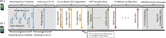
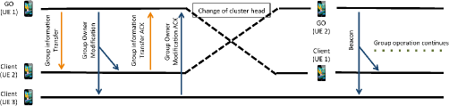
4.2.1 Cluster Formation (WiFi Direct)
In our proposal, the first step is to form a cluster among User Equipments which are willing to use D2D communications. The cluster formation procedure is mostly coherent with that defined in WiFi Direct specifications [96]. The major changes to the existing specifications are: the users/cluster heads also announce their preferred payoff distribution method in the Probe Requests; the group ownership is transferable; and the cluster head receives the LTE ID from its client and shares this information in the form of a forwarding table that contains the LTE and WiFi Direct IDs of all members. Figure 4.1 illustrates the required steps for cluster formation between two UEs. We briefly explain each step in the following.
Search and discovery. The UE either actively searches to join another UE/group by sending Probe Request over the social channels (i.e, WiFi channels 1, 6 and 11) [96] or it listens to the social channels for the Probe Requests sent by other UEs/groups. We propose to include a two-bit field to the Probe Request in order to express information regarding the desired payoff method of the UE/group. Upon reception of a desired Probe Request, the UE/ Group Owner (GO) responds with a Probe Response message which initiates the 3-way group ownership negotiation.
Group ownership negotiation. In this phase, the negotiating parties exchange their Intent value and the UE with the highest Intent becomes the GO. In WiFi Direct specification, Intent value is a number from to which shows the UE’s willingness to be GO. In our proposal, the Intent value is the average LTE Channel Quality Indicator (CQI) of the UE. The Intent value of an existing GO, is the average of the Intent values of its group members. Hence, both parties are able to compute an ex-ante revenue prior to group formation. The negotiating parties can leverage the computed revenue to decide whether to terminate or complete the connection setup.
Security setup and IP address allocation: Next, the GO initiates the WiFi security setup using Wireless Protected Setup (WPS). After the security setup is complete, GO assigns IP address to clients following the DHCP protocol.
D2D specific messages. Our proposed D2D operation requires two additional steps: each group client sends an LTE ID Notification message to the GO, which contains its LTE identity (e.g., SAE-Temporary Mobile Subscriber Identity (S-TMSI)); and the GO broadcasts the WiFi-LTE ID Association Table to all group clients.111In our proposal, two LTE IDs must be shared among cluster members: the S-TMSI which is used in the registration phase; and Cell Radio Network Temporary Identifier (C-RNTI) which is allocated to the UE after it is connected to the eNB. This message includes the LTE and WiFi Direct IDs of all cluster members. This message can also include WiFi Direct group settings such as power saving parameters, useful to quickly switch the GO when needed. Therefore, any group client can immediately become the GO without tearing down the group.
LTE-WiFi mapping. Next, each group client sends an LTE ID Notification message to the GO that contains its LTE identity. Finally the GO broadcasts the WiFi-LTE ID Association Table that includes LTE and WiFi Direct IDs of all cluster members.222In our proposal, the cluster members should share their S-TMSI and C-RNTI with other cluster members. This message can also include other group settings that are useful to quickly switch the GO when needed.
GO transfer. In WiFi Direct, the group ownership cannot be transferred. However, our proposal requires the GO to change dynamically. A GO transfer occurs when the eNB detects that another cluster member has a better cellular channel quality than the current GO (for details, see CSI reporting and Cluster head selection in Section 4.2.6). We define two messages to enable GO transfer in WiFi Direct, as shown in Figure 4.2. First, the GO sends the Group Information Transfer message to the provisioned GO. This message contains the updated list of members and their power saving parameters. Second, the GO sends the GO Modification broadcast message. Each group client should individually acknowledge this message before the GO transfer is completed.
4.2.2 Cluster Registration in LTE
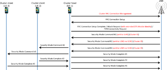
Once a cluster is formed over WiFi Direct, it should register at the LTE network. Cluster registration procedure is shown in Figure 4.3, which reports the required D2D-enabling modifications in red. This procedure consists of two phases: cluster notification; and cluster verification.
Cluster notification. The cluster formation over WiFi Direct is reported to the eNB via Cluster RRC Connection Management message with Request Cause set to connection initiation. This message also contains information such as Identity of the members and their desired payoff allocation method (see Table 4.1). The eNB responds to the cluster notification with the RRC Connection Setup message. Next, the cluster head sends the RRC Connection Setup Complete to finish the RRC setup.
| Information Elements | |
|---|---|
| Cluster Identity | To be assigned by eNB |
| Cluster Head Identity | S-TMSI |
| Cluster Clients’ Identities | S-TMSI of Client#1 |
| (for initiation, all members should be included. Otherwise, only departing/arriving member(s) are listed.) | S-TMSI of Client#2 |
| ⋮ | |
| Request Cause | CHOICE |
| Connection Initiation | |
| Arrival | |
| Departure | |
| Dedicated NAS Information (Attach Request) | |
Cluster verification. Once the RRC connection is established, the eNB sends a Security Mode Command message to each cluster member via the cluster head. We propose to include the Intent value (i.e., average CQI) of each cluster member in this message. Since the eNB is aware of real CQI, each member can verify the correctness of the values reported by others. If an anomaly is detected the member can send a negative response and leave the group. The clients send their response to the cluster head over WiFi and the cluster head forwards the responses to the eNB. By forcing the security verification to pass through the cluster head, the eNB ensures that all cluster clients are already members of the cluster over WiFi. This step is very important in terms of security because it ensures that any misreported value is detected.
4.2.3 Bearer Establishment
After cluster registration, the cluster head should initiate the cluster bearer establishment procedure. The difference between cluster bearer and UE bearer is in resource provisioning. The allocated resources for a cluster bearer are equivalent to the aggregate of resources allocated to all cluster members. LTE standard defines two types of bearers, namely default and dedicated, to support services with different QoS. The default bearer is established once a UE attaches to the network and it remains until the UE leaves the network. On the other hand, the dedicated bearer is established for services with specific QoS requirement and it remains active for the life time of the service. For brevity, we suffice to elaborate on the default bearer establishment. The procedure of dedicated bear establishment requires minor changes in the address field in order to accommodate all cluster members. The procedure for default bearer establishment is depicted in Figure 4.4, and it consists of three steps: bearer request, bearer request response, and bearer request confirmation.
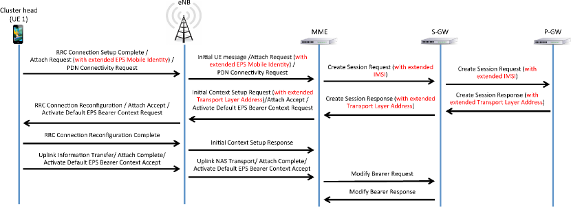
Bearer request. After cluster registration is completed, the eNB sends the Attach Request to the Mobility Management Entity (MME). The MME determines the International Mobile Subscriber Identity (IMSI) of each cluster member from the information provided in EPS Mobile Identity fields of the Attach Request. In case the IMSI of a member cannot be identified, the MME explicitly asks for it. Next, the MME sends a Create Session Request to the Serving Gateway (S-GW) which contains information such as IMSI of the cluster members and requested Packet Data Network (PDN) connectivity. The S-GW updates its EPS Bearer table and forwards the Create Session Request message to the PDN Gateway (P-GW). The P-GW updates its EPS Bearer Context Table and generates a charging profile for every member which does not have one yet.
Bearer request response. The P-GW responds to the S-GW request with Create Session Response message. In this message the address (assigned by P-GW) and QoS parameters (assigned by Policy and Charging Rules Function (PCRF) 333Here, the QoS parameters refer to both per-UE QoS parameter such as Aggregate Maximum Bit Rate (AMBR) and per-bearer QoS parameters such as QoS Class Identifier (QCI), Allocation and Retention Priority (ARP), and Maximum Bit Rate (MBR).) fields are extended to accommodate all cluster members. Naturally, QoS parameter of the cluster bearer is equivalent to the aggregate of members’ QoS. Next, the S-GW forwards the Create Session Response message to the MME which triggers the Initial Context Setup Request sent from the MME to the eNB. This message provides the eNB with settings such as the IP address and the QoS parameters of each cluster members. Again, the IP address and QoS parameters fields of the Initial Context Setup Request message is extended to accommodate all cluster members. Note that this reduces the signaling overhead compared to standard LTE operation because the network does not need to send this information to each UE separately. Finally, the eNB extracts the Attach Accept message from the Initial Context Setup Request and sends it to the cluster head in an RRC Connection Reconfiguration message.
Bearer request confirmation. The cluster head updates the cluster clients with information received from the eNB. It also sends two messages to the eNB in response to RRC Connection Reconfiguration message. An RRC Connection Reconfiguration Complete message which is basically an acknowledgment to the RRC Connection Reconfiguration and an Uplink Information Transfer message in order to complete the NAS attach process. Upon reception of RRC Connection Reconfiguration Complete, the eNB sends the initial context Setup Response to the MME. This message acknowledges that the E-UTRAN Radio Access Bearer (E-RAB) is successfully setup for the default bearer. It also provides an IP address for communication between the eNB and S-GW for downlink data transfer. After the eNB received the Uplink Information Transfer message, it sends the Attach Complete message to the MME. The Attach Complete and Active Default EPS Bearer Context Accept messages trigger the MME to send the Modify Bearer Request to S-GW. This message mainly serves as an acknowledgement. Finally, the S-GW completes the process by sending Modify Bearer Respond to the MME.
As concerns IP addressing, in LTE, each active UE has at least one default bearer and each default bearer has a unique IP address. Therefore, if a cluster member had bearer(s) before cluster formation, the P-GW keeps the existing IP address(es) associated to the default bearer(s). Once the cluster bearer is activated, the P-GW automatically terminates the old default bearer(s).
4.2.4 Mobility
In our proposal, UEs may join or leave at any time. In this section, we elaborate the procedures for departure/arrival.
Arrival. Figure 4.5 depicts the procedure followed by a new arrival. In the event of a new arrival, the cluster head sends a Cluster RRC Connection Management to the eNB with the Request Cause set to arrival (see Table 4.1). In this event, differently from cluster registration (see Section 4.2.2), the cluster head only sends the S-TMSI of the new UE. After the eNB receives the notification of new arrival, it sends a Security Mode Command to the cluster head to verify the new member. After the verification phase, the eNB sends the Cluster Bearer Resource Modification Request message, see Table 4.2, to the MME. The MME replaces the S-TMSI identity in the Cluster Bearer Resource Modification Request message with IMSI and forwards the message to the S-GW. The S-GW updates the EPS Bearer Table and sends the Cluster Bearer Resource Modification Request message to the P-GW. This initiates the standard LTE bearer modification process as described in [157]. For the sake of brevity, we will not explain the rest of the signaling messages because they follow the standard LTE-defined procedure.
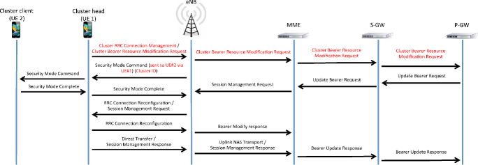
Departure. The signaling procedure for a departure is very similar to that of an arrival. The only procedural difference between arrival and departure is that the eNB does not need to send the Security Mode Command in case of departure. Moreover, according to WiFi Direct specifications, the members should send a de-authentication message to the cluster head before departure. The de-authentication message triggers the cluster head to initiate the departure procedure. Nevertheless, if a UE sends an RRC Connection Request message after it joined a cluster, the eNB assumes that the UE does not belong to a cluster anymore.444Our proposal does not permit UEs to have user bearer and cluster bearer simultaneously. In this case, the eNB initiates the departure procedure without receiving the departure notification message from the cluster head. If a UE is reported as a new arrival of a cluster (i.e., ) while it is listed as a member of another cluster (i.e., ), the eNB initiates the departure procedure for and an arrival procedure for .
| Information Elements | |
|---|---|
| Identity of Departing/Arriving Member(s) | S-TMSI(s) |
| Request Cause | CHOICE |
| Arrival | |
| Departure | |
4.2.5 Data Plan Operation
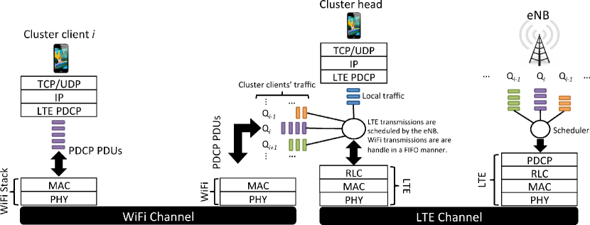
Figure 4.6 illustrates the adaptation of LTE and WiFi Direct data protocol stacks to our proposal. We choose to bridge, at the cluster head, the WiFi Direct MAC and LTE at Packet Data Convergence Protocol (PDCP) layer for three reasons: LTE packets are ciphered and integrity-protected in the PDCP layer using keys which are only known to the client and the eNB. Therefore, other UEs cannot decipher the LTE packets traversing the WiFi network; the cluster head can further process PDCP Packet Data Unit (PDU)s in RLC layer for concatenation/segmentation according to its LTE physical link quality; and the WiFi Direct MAC provides a robust and secure transmission service, and natively allows to send frames to be relayed at MAC layer. Note that the resulting LTE and WiFi Direct data transfer operations are decoupled. Indeed, the cluster head uses the legacy ACK/NACK to secure all the handled LTE traffic, so that ARQ/HARQ operations are managed at the cluster head only, as if the exchanged LTE PDUs were all belonging to the cluster head. Similarly, the normal ACK and retransmission mechanisms are used by the WiFi Direct interface to transfer LTE PDUs in a legacy 802.11 payload.
Uplink. As concerns uplink transmission requests, the clients send their Scheduling Request (SR) or Buffer Status Report (BSR) to the cluster head to be forwarded to the eNB. The eNB uses Downlink Control Information (DCI) to inform UEs regarding their downlink and uplink resource allocation. Since the cluster head is the only member which is listening to the LTE channel, it receives the DCI and updates the clients with the scheduling decision made by the eNB, using an 802.11 management frame with the same subtype value used by the UEs to encapsulate SR and BSR messages in the WiFi Direct frame. As concerns data packets, the scheduled cluster clients encapsulate the LTE PDCP PDUs in WiFi frames and send them to the cluster head. The cluster head extracts the PDCP PDUs and forwards them to the eNB in the designated slot. The cluster head transmits the packets to the eNB with the client’s C-RNTI address in order to simplify the identification of the real source of the packets for the eNB. Since LTE data packets are ciphered and integrity protected, there are no security concerns and threats in operating LTE relay over WiFi Direct as described in this chapter.
Downlink. The eNB transmits the packets using the client’s C-RNTI address but it selects the MCS according to the cluster head’s channel quality. Since the cluster head is aware of scheduling plan for its clients, it listens to the downlink channel to receive the packets belonging to all cluster members. Next, the cluster head encapsulates the PDCP PDUs in regular WiFi data frames that include the source and destination MAC addresses of cluster head and client, and the default MAC address of the eNB.
4.2.6 Adaptation of LTE Procedures
So far we have defined the required messaging to support our proposed architecture in LTE and WiFi Direct. Here, we elaborate on the adaptation of our proposal to other important operations.
4.2.6.1 CSI reporting
In LTE, UEs send CSI reports to the eNB for scheduling purposes. In our proposal, the cluster head sends the CSI reports of all cluster members to the eNB. This creates some flexibility which does not exist in the standard LTE operations. For example, the cluster clients can report the CSI over all sub-bands to the cluster head over WiFi. Then the cluster head filters these reports and sends the list of top candidates on each sub-band to the eNB. Alternatively, the cluster head reports the n highest CQI to the eNB. The value of imposes a trade-off between opportunistic gain and spectral efficiency. Note that such a high resolution CQI report would not be possible in normal LTE operations.
4.2.6.2 Cluster head selection
The eNB selects the cluster head among the cluster members based on the reported CSIs. We propose to add an extra field to the DCI so that the eNB can transmit the C-RNTI of the new cluster head to the current cluster head, which can trigger the GO transfer procedure. The cluster head selection interval is implementation-specific and it is constrained by the delay of LTE network and group ownership transfer in WiFi Direct. This interval introduces a trade-off between signaling overhead and opportunistic gain. On one hand the opportunistic gain is maximized when the cluster head is selected on a per-frame basis (shortest possible interval). On the other hand, per-frame cluster head selection requires higher signaling overhead.
4.2.6.3 Label Switching
The relay UE experiences high computational overhead due to LTE frame processing. Hence, we propose label switching at LTE PDCP layer instead of IP routing which is the current solution in 3GPP. As mentioned earlier, the byproduct of this design choice is the elimination of relay-related security concerns.
4.2.6.4 Scheduling
The existing LTE scheduler can be adapted to support our proposal with a minor modification. In LTE, the eNB selects the physical layer parameters based on the CSI of the scheduled UE. However, our proposal requires the eNB to select physical layer parameters according to the CSI of the cluster head so that the cluster head can decode the packets and forward them to the corresponding clients. Note that the eNB still uses the C-RNTI of the client in the DCI so that the cluster head is aware of its transceiving schedule in uplink and downlink. This also eliminates the need for an uplink intra-cluster scheduler in the cluster head.
4.2.6.5 Security
As mentioned earlier, our proposal does not introduce any new security threats to the existing LTE architecture because the LTE packets are ciphered and integrity-protected before forwarding. We also propose to send Security Mode Command through the cluster head, so that the cluster head cannot exploit a UE’s resources that is not present in the cluster. The only possible attack is a malicious cluster head that drops packets of its clients. The eNB can detect such behavior by tracking communication failures of each cluster head and act accordingly.
4.2.6.6 Policy control and charging
Since the cluster head is in charge of the LTE transmissions for all cluster clients, it is important to make sure that the cluster head is not billed for the clients’ traffic. The policy control and charging of LTE is done via Policy and Charging Enforcement Function (PCEF) which charges the UEs based on their IP address. Since each cluster member is given a separate IP address, our proposal does not introduce any problem in billing. It is also important to ensure that members do not utilize each other resources. Since the eNB schedules the members individually, utilizing the other cluster members’ resources is not a concern. In case a malicious cluster head transmits its own packets on a slot allocated to another member, the eNB discards the cluster head data because it cannot be deciphered.
4.3 Summary
In this chapter, we proposed a practical protocol for supporting D2D communications in cellular networks using WiFi Direct and LTE. This protocol, to the best of our knowledge, is the first of its kind. Specifically, we detailed how D2D communications can be supported over LTE network with minor modifications to the standard procedures without any infrastructural changes. We first adapted the WiFi Direct group formation procedure to support dynamic cluster formation and LTE specific message exchange. Then, we introduced the necessary signaling messages for cluster registration and bearer setup in LTE. We showed that most of the required pieces are in place and we only need to amend some of existing messages to support D2D clustering. Finally, we discussed the impact of D2D clusters on LTE operations such as billing and security. Our studies revealed that all native LTE operation work with D2D clusters. Moreover, D2D clustering does not impose any security threat which does not already exist in legacy LTE systems.
Chapter 5 Experimental Evaluation
5.1 Introduction
Analytical studies on D2D communications demonstrate very promising results, but there is no experimental evidence that validates these results to date. Moreover, the 3GPP study is mostly focused on the description of the architecture and procedure for D2D communications. As of today, their proposed architecture of ProSe remain unevaluated. The lack of experimental studies is mostly due to tedious process of prototyping complex cellular architecture and expensive equipments that are associated with it. Nevertheless, thanks to the advent of SDR, the experimental studies for D2D communications are now made possible. In this chapter, we elaborate on the development procedure of outband D2D communications using a National Instrument’s SDR platform. Next, we leverage this platform to answer questions such as: How is the cross-platform (LTE to WiFi) communication? What is the delay and the computational overhead? How large is the throughput gain in presence of real channel dynamics?
5.2 SDR-based Testbed for Outband D2D Communications
In this section, we describe the hardware, the software, and the architecture of our testbed. Our testbed design is utterly beneficial because it is based on an SDR platform that uses Field Programmable Gate Array (FPGA) modules for high-speed Digital Signal Processing (DSP) prototyping. Moreover, it exploits the real-time controllers which ensures quick protocol prototyping. As today’s cellular networks are moving toward functional virtualization and new architecture, SDR platforms certainly stand out among the prototyping alternative in today’s market.
5.2.1 Software and Hardware
Hardware. The hardware used in this testbed is NI PXI 1082 chassis111http://sine.ni.com/nips/cds/view/p/lang/en/nid/207346 that contains: NI PXIe 8135 Real-Time controller222http://sine.ni.com/nips/cds/view/p/lang/en/nid/210545 operating on an Intel Core-i7-3610QE CPU. This controller is used to execute LabVIEW Real-Time which runs MAC layer algorithm and physical layer control algorithms. LabVIEW Real-time communicates with the FPGA through dedicated direct memory access FIFOs; The Physical layer is programmed using LabVIEW FPGA and runs on NI FlexRIO modules333http://www.ni.com/flexrio/ that are equipped with Xilinx Kintex 7 or Virtex 5 FPGAs; NI 5791 FlexRIO Adaptor Module (FAM) is used as an RF transceiver operating with a MHz bandwidth the in frequency range MHz to GHz. This is used for Digital to Analog Conversion (DAC), Analog to Digital Conversion (ADC), up-converting base-band to band-pass, and down-converting band-pass to base-band. Figure 5.1 illustrates all these components.
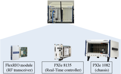
Software. We found LabVIEW444http://www.ni.com/labview/ as a suitable tool to prototype an outband D2D platform. On one hand, LabVIEW FPGA allows for quick implementation of computationally intensive Physical layer (PHY) operations (e.g., Fast Fourier Transform (FFT), inverse Fast Fourier Transform (iFFT), encoding, and decoding) in Xilinx FPGA and meets the stringent nano-second time scale requirement of the digital communication systems. Moreover, it provides the necessary means for high speed communication with CPU and Radio Frequency (RF) hardware. On the other hand, LabVIEW Real-Time is suitable for implementing MAC layer operations with micro-second resolution. LabVIEW Real-Time runs on a general purpose CPU and communicates with LabVIEW FPGA over high-speed PCIe backplane.
5.2.2 Architecture of eNB
The eNB consists of a Real-Time controller and a FlexRIO module used for Over The Air (OTA) LTE transmission. Figure 5.2 shows the important blocks of the eNB. Real-Time controller runs MAC layer services such as scheduling, D2D services, and Transport Block (TB) generation for Control CHannel (CCH) and shared channel Shared CHannel (SCH). FPGA executes PHY operations such as convolutional coding, interleaving for CCH traffic and scrambling for SCH traffic. Finally, the base-band signal is up-converted in the FAM module and transmitted to the UE OTA. The current testbed only supports OFDMA in downlink and the uplink transmissions is performed over ethernet. However, in future we intend to extend this testbed to support OFDMA uplink transmission.
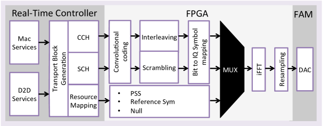
5.2.3 Architecture of UE
As eNB only requires one interface, UE’s architecture is thus more complex since it comprises two interfaces: an LTE OFDMA downlink receiver for communicating with the eNB; and a WiFi transceiver to establish the outband D2D link with other UEs.
OFDMA receiver. Following the design of the transmitter, the DSP operations are implemented in the FPGA. Real-Time controller is only used for processing the received payload and MAC layer D2D operations. These operations mainly consist in filtering the relay packets and transmitting them to the WiFi interface for relaying. Figure 5.3 shows the location of different logical blocks in the system.
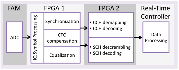
WiFi transceiver. The majority of the WiFi framework [158] is implemented in FPGA. In addition, the transceiver is implemented within the same FPGA. We implemented the D2D state-machine and its corresponding logic in the Real-Time controller. The controller is also in charge of feeding data to the FPGA transmission processing chain and reading the decoded data from FPGA reception processing chain. Figure 5.4 shows the structure of the WiFi framework.
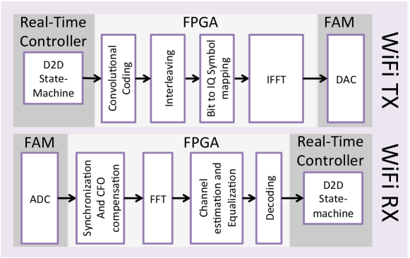
Communication. We observe in Figure 5.5 that UEs receive downlink transmissions over the OFDMA receiver and send the uplink messages over an ethernet link. The WiFi (i.e., D2D) transmission uses an OFDM transceiver.
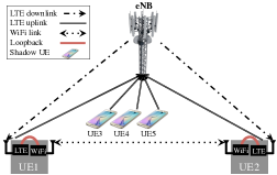
5.2.4 Shadow UEs
These non-SDR UEs (i.e., UE3, UE4, and UE5 in Figure 5.5) are off-the-shelf android smartphones. We include the shadow UEs in our setup to better capture the performance of outband D2D in a real-world scenario. We developed an android application to obtain real-time cellular channel quality on a millisecond basis. The application then transmits the channel quality values to an access point, which is connected to the eNB over an ethernet link. Although the shadows do not receive the actual transmission, the eNB schedules them and transmits their data as if they were real UEs. Since the MCS-SNR mapping is constructed to ensure block error rates below , we assume that the shadows receive the transmitted blocks with success probability of .
5.2.5 Synthetic Fading
We measure the selected KPIs under different scheduling schemes. Due to the limitation in the number of equipments in our disposal, we should run each experiment at a separate time instant. In an ideal case, the system can be connected to high-end multi-channel cellular channel emulators to create the same channel variation in each experiment. Since we do not have such a device, we decided to create a repeatable channel variation situation using refractors.
In order to create repeatable channel variation patterns, we mounted the refractors plates on a step motor that is controlled by an Arduino Uno555http://www.arduino.cc/en/Main/ArduinoBoardUno micro-controller. We generate synthetic channel variation by changing the rotation speed of the step-motor. Figure 5.6 is the proof of concept of this mechanism. We repeated an experiment four times and plotted the CDF of the potential MCS (obtained from channel qualities) for both UEs to ensure stable repetitions of the channel variation. Indeed, the results show that this approach is suitable to re-create the same channel environment for different experiments. Note that the location/frequency is selected such that unpredictable interference is minimized.
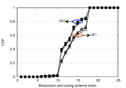
5.3 Experimental Evaluation
In this section, we experimentally evaluate the performance of outband D2D-relay and our proposed protocol. We design several experiments to better demonstrate the system behavior in different scenarios. We first present the performance of a simple outband D2D-relay setup. The simple setup is then redesigned to first incorporate channel opportunism and then QoS-awareness. We also examine the impact of non-collaborative UEs (i.e., shadow UEs). The duration of each experiment is seconds, which is sufficiently long to observe the average system’s performance. In order to provide the reader with a detailed view of the achieved performance, we show minimum, maximum, 25th and 75th percentiles in addition to the average values. Unless otherwise specified, the rotation speed of the refractor is rpm. Finally, UE2 experiences higher average channel quality than UE1 in all experiments.
5.3.1 Algorithm Implementation
We implement DORE, a channel-opportunistic framework for enhancing network capacity under QoS constraints. DORE is based on the aforementioned channel opportunistic design in previous chapters. In addition to channel opportunism, we add delay consideration to our implemented algorithm for better QoS-awareness. The delay consideration enables our proposed D2D scheme to serve a much larger variety of application in particular those with tight delay requirements. Algorithm 1 is the pseudocode of DORE. In the algorithm, we first calculate the achievable throughput of the cellular link and the D2D link . Then Merge and Split algorithm uses the potential throughput information of the links (throughput is zero if the link can not be established) for cluster formation. Next, the algorithm compares the achieved delay over the D2D link with the application specific threshold to decide whether it should keep the D2D link active () or it should fall back to cellular link (). It should be noted that we do not use the game theory-based dynamic cluster formation algorithm in our experimental evaluation because the testbed consists of only two static UEs.
5.3.2 Selected KPIs
We report several KPIs to examine different aspects of outband D2D-relay and DORE. The KPIs described below are chosen based on their importance for understanding the characteristics of a practical D2D system.
Throughput. Throughput is measured as the number of received bits per second.
Delay. We timestamp each packet at the eNB MAC and measure the delay at three points within the path from the eNB to the D2D receiver. The delay from the eNB MAC to the relay-UE MAC is referred to as LTE delay. The delay from the relay’s LTE MAC to WiFi MAC is called the cross-platform delay. WiFi delay is the time from the relay WiFi MAC to the D2D receiver WiFi MAC. The end-to-end delay is the sum of all these delays. Note that the cross-platform delay is affected by our implementation using multiple FPGA card for WiFi and LTE interfaces.
CPU load. Since the Real-Time controller executes D2D related operations, we can calculate the extra CPU load due to D2D operations by monitoring the Real-Time module.
D2D lifetime. We examine our proposed design with slow and fast channel variations. In each case, we measure the time during which a UE acts as relay, which we call relay lifetime. This is an important factor in opportunistic D2D because frequent role switching imposes extra load to the system.
Structural Similarity (SSIM) This is an index of similarity between two images and it is known to be a better estimation of human eye perception in comparison to other traditional methods such as peak SNR or mean squared error. We use this metric for Quality of Experience (QoE) measurements in video streaming experiments.
5.3.3 Non-opportunistic Outband D2D Relay
We start with the simplest form of outband D2D-relay scenario with two UEs. Despite the simplicity of this experiment, it provides answers regarding the delay overhead due to multi-hop communication and achievable throughput gain.
Figure 5.7(a) compares a Legacy scheme (in which both UEs receive traffic only from the eNB) with an Outband D2D-relay, in which UE1 acts as relay for UE2. We observe that outband D2D increases the average end-to-end delay (i.e., Total in the figure) by ms as compared to the Legacy cellular system. Looking at different delay components of outband D2D-relay, we can see that cross-platform delay and WiFi delay are the major contributors to the delay overhead. It is important to note that extra frame processing results in higher LTE delays in outband relay mode. While commonly ignored in the literature, this illustrates that relaying large volumes of traffic comes at a cost. According to the observation from the delay profile, outband relay could be potentially suitable for a large variety of non-mission critical applications. Indeed, outband relay with a total delay of ms meets the 3GPP suggested delay budget of ms [145]. The motive for opportunistic D2D-relay is vividly depicted in Figure 5.7(b). The figure shows that UE2 suffers from low channel quality while UE1 experiences a good channel condition. After outband D2D activation, UE2’s throughput increases significantly because it receives its traffic through a high channel quality relay.
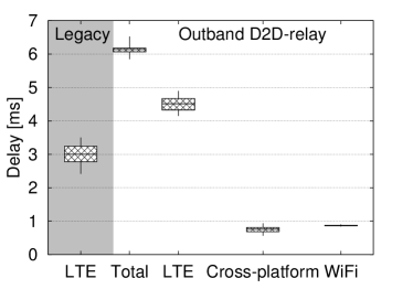
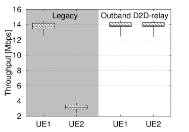
5.3.4 DORE with Delay-tolerant Traffic
Now, we evaluate the performance of opportunistic outband D2D using RR and PF scheduling algorithms. We test DORE with delay-tolerant traffic to evaluate the potential throughput gain for such use-cases. In the figures, we label the legacy schemes as RR and PF. When used for DORE with delay-tolerant traffic, they are labeled as RR-DT and PF-DT.
Figure 5.8(a) shows the achievable aggregate throughput of RR-DT and PF-DT is % and % higher than RR and PF, respectively. As mentioned, opportunistic outband D2D leverages the channel diversity between the D2D users. Since PF harvests part of this opportunism due to its opportunistic nature, the resulting gain reduces by % in comparison to RR. Nevertheless, the gain remains relevant for a two-user scenario where there are limited opportunities. We show later in this section that the opportunistic gain increases with the user population. Delay comparison in Figure 5.8(b) demonstrates DORE causes higher delays. The additional delay stems from WiFi and cross-platform transmission and LTE frame processing.
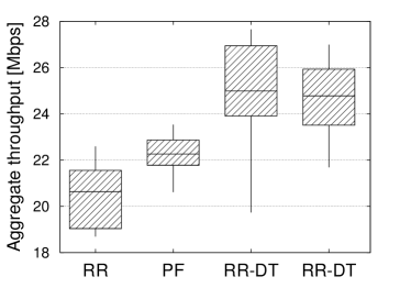
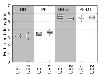
5.3.5 Impact of Fading Speed
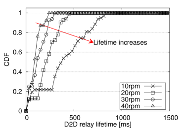
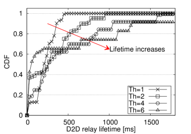
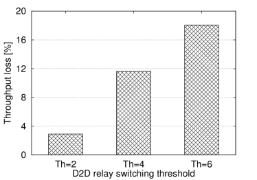
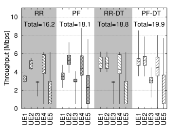
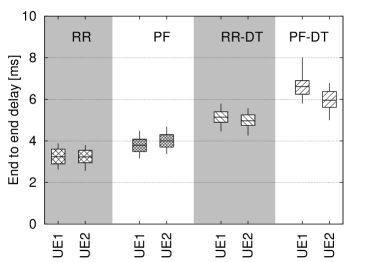
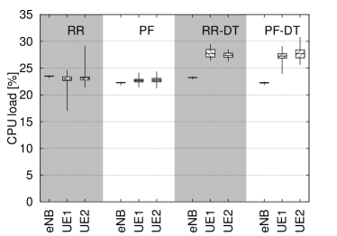
This experiment is designed to show the dynamics of DORE under different fading scenarios. In particular, the change of role in the D2D connection (i.e., a UE can be a relay or a D2D receiver). We refer to the period in which a D2D UE acts as relay as the lifetime. In this experiment, we shed light on the frequency of these changes and their impact on the system.
Figure 5.9(a) shows the CDF of the lifetime of UEs when the refractor surface spins at , , , and rpm. At these rotation speeds, the MCS of a UE remains the same for ms, ms, ms, and ms, on average. We can see that the duration of the lifetimes increases as the fading speed reduces. The results also show that regardless of fading speed, the lifetime is shorter than ms more than % of the time. This emphasizes on the fact that any implementation of opportunistic outband D2D must be capable of handling the relay dynamics on a millisecond timescale.
In our implementation of DORE, a switch of D2D roles occurs as soon as the achievable MCS of the D2D receiver becomes higher than the one of the relay UE. In other words, the MCS difference threshold to switch roles is one MCS index. Nevertheless, considering the resulting short lifetimes depicted in Figure 5.9(a), we have decided to introduce and test hysteresis in the switching to reduce frequent switching. Introducing higher switching threshold can avoid role changes due to small MCS variations that do not vary much in terms of bit efficiency. Thus, we increase the MCS difference that triggers the role switching. Figure 5.9(b) shows that larger thresholds (Th in the figure) increase lifetimes, as expected. However, this increment comes at the cost of reduced throughput. Indeed, Figure 5.9(c) illustrates that the throughput reduces up to % when the switching threshold is MCS levels. Our results indicate that small switching thresholds increase D2D lifetime with limited throughput penalty. Therefore, it is not strictly necessary to reconfigure D2D links upon any MCS change, which reduces the complexity of the implementation.
5.3.6 DORE in Presence of Shadows and Delay-tolerant Traffic
Here, we emulate the presence of additional legacy UEs using the shadow UEs introduced in Section 5.2.4. The shadows do not collaborate in DORE but they help us to test DORE in presence of non-collaborative UEs. The shadows send real-time CQI reports to the eNB, and the eNB schedules traffic for them, although they cannot decode such traffic.
Per-UE throughput results are presented in Figure 5.10(a). We can see that UE1 achieves a % throughput gain with DORE (i.e., RR-DT and PF-DT) while UE2 only achieves a mere % throughput gain. UE2 achieves lower gain due to its higher average channel quality. We also reported the aggregate throughput of each scheme in Figure 5.10(a), marked as Total. DORE results in % and % throughput gain compared to RR and PF. The throughput gains are lower than those achieved in the previous scenario (%). This is because in a scenario with UEs, the relay UE receives only a fraction of the total available bandwidth (i.e., of the resources can be relayed if RR-DT is used). As a result, the opportunistic scheme can only optimize that portion of the cellular resources.
Figure 5.10(b) depicts the end-to-end delay. The delay behavior of the UEs is very similar to the delay behaviors observed in Figure 5.7(a). Both UEs experience additional delay under RR-DT and PF-DT w.r.t. RR and PF because of the aforementioned cross-platform and WiFi delays. UE1 has a higher delay than UE2 because it has lower channel quality than UE2 and it acts as the D2D receiver most of the time. However, the increased delay is quite limited and can be substantially reduced by using dedicated and integrated hardware rather than different FPGA cards for LTE and WiFi interfaces.
Figure 5.10(c) compares the CPU load of the eNB and the UEs. The overhead on the eNB is negligible. The two D2D-enabled UEs experience and higher CPU load due to outband D2D operations in WiFi and LTE interfaces. Note that running the WiFi code in the idle mode on the Real-Time controller increases the total CPU load by about %. Hence, the overhead due to outband D2D is marginal.
5.3.7 DORE in Presence of Shadows and Delay-sensitive Traffic
In this experiment, UE1 and UE2 host a real-time gaming application and a VOIP call with ms and ms OTA delay threshold, respectively. To highlight the impact of DORE’s QoS-awareness, we also show the performance figures when the delay thresholds are set to infinity (i.e., DORE ignores the delay constraints). In this scenario, we stressed the WiFi channel (i.e., D2D link) by introducing extra non-D2D traffic to the network so that the WiFi channel operates near to the congestion point. Therefore, small changes in the instantaneous channel quality provoke non-negligible size queues.
Figure 5.11(a) shows the aggregate throughput of DORE with RR and PF but without QoS constraints (RR-DT and PF-DT in the figure) and with tight constraints (RR-DS and PF-DS). Both RR-DS and PF-DS achieve slightly lower throughput () w.r.t RR-DT and PF-DT because the QoS-awareness of DORE prevents opportunistic relay when delay constraints are violated. However, the throughput loss is a small price to pay to maintain the QoS requirements of the time-sensitive applications. Indeed, we observe in Figure 5.11(b) that DORE can successfully cap the average delay below 30 ms and 80 ms. The effectiveness of DORE is especially seen when it reduces the packet delay of the voice traffic from ms to ms and ms. Since DORE delay control mechanism relies on UE feedbacks, it cannot avoid the delay caused by dramatic channel variations. As a result, the maximum delay under RR-DS and PF-DS can be higher than the delay thresholds.
5.3.8 QoE with DORE
Good QoS does not necessarily corresponds to good QoE. Thus, we design a video streaming scenario using VLC666http://www.videolan.org/vlcto measure the QoE in terms of SSIM. We use AviSynth to measure SSIM. Both PF and RR demonstrated similar trend hence we only show the result for PF, for brevity. Again, we show in Figure 5.12(a) the SSIM of the received video with ms delay constraint (i.e., PF-DS) and with an infinite one (i.e., PF-DT). We repeat the experiment for three different videos with 240p, 360p, and 480p resolutions. The results indicate that the QoS awareness of DORE results in up to SSIM improvement. The SSIM values degrade with higher resolution videos because they are more sensitive to channel impairments. We also demonstrate a snapshot of the received video for 240p and 360p resolutions, in Figure 5.12(b). As expected, tight QoS constraints result in better image quality.
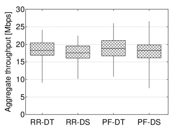
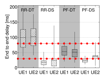
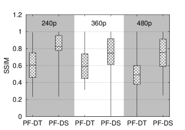
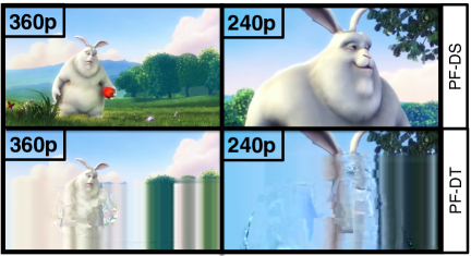
5.3.9 Opportunistic Relay within Large Relay Groups
In the previous experiments, only two UEs were allowed to collaborate in DORE. Our observation in Figure 5.10(a) showed that the impact of opportunistic outband relay with only two users is limited. Since one-to-many communication is also present in 3GPP ProSe services, we can increase the size of the outband D2D group in order to achieve higher throughput. This experiment is designed to illustrate the impact of larger D2D UEs groups. Here, all UEs report their CQIs to the eNB and we only measure the throughput at the LTE because the shadows are commercial smartphone, which are unable to decode the messages of our experimental eNB. Figure 5.13 shows the aggregate system throughput. Our results confirm that by enlarging the outband D2D group from to UEs, the network throughput increases up to %. The result is critical to confirm the potentials of opportunistic D2D schemes. Indeed, we are the first to assess the opportunistic gain with multiple UEs relaying traffic among each other with a real implementation of an eNB scheduler and real-time CQI acquisition from multiple UEs. The reported results are obtained under PF scheduling. The achievable gains are even higher with RR, as shown in prior subsections.
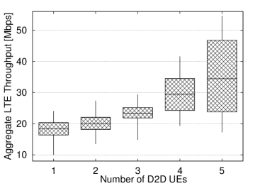
5.4 Discussion
This chapter provides in-depth intuitions to understand the practicality of integrating outband D2D communications in cellular networks. Here, we discuss the feasibility of such integration in order to enlighten some key requirements for developing an experimental setup as well as for designing possible use-cases.
Feasibility. The SDR-based implementation of DORE is the proof-of-concept for the feasibility of outband D2D schemes with more complex and dynamic scenarios than non-opportunistic and QoS-unaware UE to UE communications.
Implementation. There are several challenging issues to solve for SDR implementation of a D2D system. Here, we point out the most critical ones. The relay UE experiences high computational overhead due to LTE frame processing. Hence, we use label switching at LTE PDCP layer instead of IP routing which is the current solution in 3GPP. During the course of DORE implementation, we realized that D2D UEs switch role with high frequency (in order of milliseconds). Thus, we place DORE at the eNB instead of ProSe Function/Server to meet timing constraints and to avoid the additional overhead on the backhaul links.
Choice of platform. To date, there are a few SDR platforms with ‘simultaneous’ LTE and WiFi capability, namely, Open Air Interface, and LabVIEW. We choose LabVIEW for its modular and graphical programming structure that allows for quick real-time and FPGA code development without stepping into complex low-level programming languages. The choice of the NI PXI-based platform over USRP is due to the real-time capability of the PXI system that speeds up MAC layer algorithm prototyping and testing.
Capacity. DORE is key for boosting network capacity in one-to-many relay scenarios. This result is very promising and it may suggest to increase the size of the relay groups as much as possible. However, in virtue of our observations on the extra load due to relay operations, it is plausible to suggest that each relay group should not include more than a handful of users, which is enough to enhance the network capacity by .
QoS. QoS provisioning is a concern in outband D2D due to the use of unlicensed spectrum. As a result, we designed DORE and the surrounding protocol with necessary feedback and handlers to enable QoS monitoring in our testbed. The experiments confirmed that DORE achieves the QoS requirements using a simple monitoring and feedback scheme.
Use-cases. Our experimental evaluation showed that (opportunistic) outband D2D schemes have low latency and ameliorate the throughput substantially. Hence, these schemes suit a large variety of applications including voice calls, video streaming, real-time gaming, and content sharing.
5.5 Summary
We prototyped the first SDR platform for outband D2D communications. We leveraged Xilinx FPGAs and the NI Real-Time OS to develop realistic experiments with LTE-like millisecond CQI reporting, scheduling, and high-speed LTE- WiFi interaction. Our experimental evaluation using several QoS and QoE metrics confirmed the feasibility and potentials of opportunistic outband D2D communications. The results revealed that experimental performance figures are lower than the reported values in the prior analytical studies, although still notable (up to 20% with just two users). Nevertheless, high throughput gains are achievable if the number of participating UEs in opportunistic outband D2D increases (up to 71% with five users). Finally, we are in the process of providing public access to our D2D SDR implementation so that the research community can benefit from deeper study of such a system.
D2D for Network Optimization
Chapter 6 D2D Mode Selection
6.1 Introduction
There have been extensive research efforts in both academia and industry to explore D2D techniques [2]. D2D communications have been considered for a large variety of use-cases such as cellular offloading [159], mobile relaying [12], and video streaming [160]. These studies indicate the potential outstanding gain of D2D communications in cellular networks. Indeed, the high performance gain motivated leading telecommunication companies such as Qualcomm to perform experimental studies on this paradigm using early stage prototypes [4]. Standardization bodies such as 3GPP have also joined this front by considering D2D communications as a public safety feature in the next release of LTE-A [86]. These efforts from academia, industry, and standardization bodies confirm that the society regards D2D communications as a crucial feature for next generation networks. Nevertheless, there is still no concrete agreement on D2D operational details such as which medium access control to adopt, or which spectrum allocation schemes, connection setup, and resource management protocols are to be implemented. As described in Chapter 2, initial proposals for D2D communications aimed at re-using the same resources that are used for conventional cellular communications (i.e., inband underlay D2D mode) [74]. The significance of the D2D gain had led to proposals in which a part of the cellular resources is dedicated only to D2D communications (i.e., inband overlay D2D mode). Finally, the scarcity and the high price of cellular spectrum motivated some researchers to explore D2D communications over the unlicensed band (i.e., outband D2D mode). The use of resources with these D2D modes is illustrated schematically in Figure 6.1.
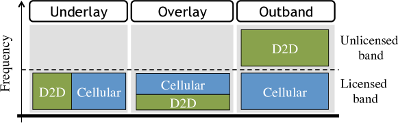
The majority of the existing studies on D2D communications select one of the aforementioned modes, then propose a method for resource allocation/interference management in order to handle the resulting complications, and finally illustrate the achievable performance improvement [109, 12, 74, 79, 159]. However, single mode D2D significantly limits the system performance to the interference profile of the network. Existing multi-mode D2D systems only focus on inband D2D modes, i.e., fully dependent on cellular spectrum. Other proposals focus on joint scheduling and mode selection [108, 161], although they are extremely complex (more complex than scheduling, which is already proven to be NP-hard for cellular systems such as LTE [162]) and introduce unnecessarily frequent mode selection decisions.
Interestingly, while some researchers limit D2D communications to cellular spectrum, the standards have a more liberal view of D2D. In fact, 3GPP defines D2D as “the communication between two users in proximity using a direct link between the devices without traversing the eNB(s) or the core network” [86]. We also remark that network-assisted outband D2D is accounted for in 3GPP ProSe [7]. Although both inband and outband D2D are considered valid options for ProSe services, there is no indication on how to select between the two. Hence, given the fast-track emergence of D2D communications in cellular networks, the need for an adaptive D2D mode selection scheme is beyond question.
In this chapter, we propose a flexible framework to adaptively select D2D mode or operating band and technology. In particular, we first discuss the practical implications of each D2D mode based on the latest standard releases of LTE-A and WiFi-Direct. This discussion clarifies that there is no superior D2D mode and the potential of each mode is highly scenario/use-case dependent. After discussing practical implementation issues of D2D-enabled networks, we provide analytical insights into the mode selection problem in an innovative multi-mode multi-band setup, which accounts for both achieved throughput and energy costs. We call such a novel approach Floating Band D2D, because D2D transmissions can occur on either inband or outband modes. The problem is formulated as a non-linear integer programming problem. Given the NP-hardness of the problem and time-stringent requirements of future cellular networks, e.g., 5G networks, we propose three practical heuristics with near-optimal performance and low complexity. Finally, we evaluate the performance of the proposed heuristics in a multi-cell scenario using a realistic setup designed based on the ITU-R guidelines for evaluating IMT-Advanced networks [163]. Our results confirm that the coexistence of D2D modes ameliorates the performance of the system in terms of the key performance factors such as throughput and utility (up to one order of magnitude), and near complete fairness.
6.2 Pros and Cons of D2D Modes
As mentioned, 3GPP’s definition does not restrain D2D implementations to a specific technology or spectrum. To date, the available commercialized technologies that suit D2D communications are either in the family of 3GPP standards such as LTE-A or in the family of IEEE standards such as WiFi. The former are suitable candidates for inband D2D and the latter match the requirements of outband D2D. Indeed, the feasibility of D2D communications with the aforementioned technologies has recently been theoretically proven not only by us in [11] but also by other independent studies [164].
We refer to users that communicate with the eNB as cellular users and to those who communicate with other neighboring users as D2D users. The following describes the list of D2D modes available are Underlay inband, Overlay inband, and Outband. Note that inband D2D users are allowed to share the same resource (i.e., simultaneously transmit over the same frequency), while outband D2D users adopt a WiFi MAC and contend for channel access. The differences among available D2D modes pose advantages and disadvantages for each mode, as summarized in Table 6.1. For completeness, we also include legacy cellular communication in the table. Interestingly, none of the available D2D modes can simultaneously guarantee features like controlled interference, spectrum efficiency, and QoS. So, when it comes to electing a specific mode for implementing D2D in a network, there is no clear winner.
| Underlay | Overlay | WiFi | Cellular | |
|---|---|---|---|---|
| Interference between D2D and cellular users | ||||
| Interference among D2D users | ||||
| Needs dedicated resources for D2D users | ||||
| Controlled interference environment | ||||
| Simultaneous D2D and cellular transmission | ||||
| Increased spectral efficiency | ||||
| Requires additional wireless interface | ||||
| QoS guarantee | ||||
| Energy cost | Eq.(6.3) | Eq.(6.3) | Eq.(6.5) | Eq.(6.2) |
Looking at the pros and cons of the available D2D modes, one can observe that none of the available D2D modes is ideal. So the question remains: Which D2D mode is the best? Let us look at a few examples to better address this question. The use of underlay in micro cell scenarios, where users are in short range, results in intolerable co-channel interference to cellular users. In such scenarios, overlay and outband modes better facilitate D2D communications. On the other hand, using overlay in a macro cell with many cellular users can result in underutilization of network resources if the number of D2D users is small. Here, underlay and outband potentially perform better because of the sufficient distance among users. Finally, places with high occupancy of unlicensed band are not suitable for outband mode, due to well known congestion problems of contention-based MAC protocols.
One can observe that an eNB may face the above-mentioned scenarios on a daily basis, e.g. as different groups of users (workers/students, residents, shoppers, etc.) become dominant at particular times of the day. Thus, an adaptive scenario-independent D2D-enabled system cannot be tied to a specific mode or band. Indeed, we propose a multi-band mode selection scheme in order to facilitate such high level of adaptiveness in real implementations.
6.3 System Model
In this section, we describe our reference system, our proposed mode selection approach, and its practical implications.
6.3.1 System
We consider a hexagonal multi-cell LTE-A network with a reference cell in the center and its first-tier neighbors as shown in Figure 6.2. The cell consists of users labelled as . Downlink and uplink channels are separated and each one has a fixed bandwidth. Users may communicate with other users in the cell or with those outside the cell. If a user wants to communicate with another user in her proximity, she can use D2D communications. Inband D2D communications use uplink cellular spectrum [86]. It is assumed that each user communicates with (at most) one user at any given time. Each connection between users and is referred to as , . For notational convenience, the eNB is addressed as user . Here, we assume that the outband D2D exploits WiFi Direct technology. With the above, we use four communication modes operating:
Our system operates in discrete time units and the eNB is in charge of mode selection and scheduling. The eNB makes the scheduling decisions on a per-frame basis. Each frame consists of subframes. In each subframe, only one cellular user is scheduled, while the number of concurrent D2D transmissions is not limited a priori. Therefore, there is no interference among cellular users (i.e., mode ), but underlay users (i.e., mode ) interfere with the cellular and other underlay users (i.e., modes and ). Overlay users only interfere with each other, while outband D2D users simply contend for the WiFi channel. A fixed portion of cellular bandwidth is dedicated to overlay D2D users. This portion is released to cellular and underlay users if there is no user in overlay mode.
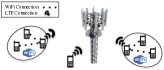
6.3.2 Mode Selection and Scheduling
As mentioned, mode selection and scheduling decisions by nature require decision making schemes with a different time-scale resolution. Thus, we propose to decouple the mode selection and scheduling problems. The decoupling is mainly inspired by the fact that D2D connections last more than a few frames in a real world scenario and scheduling them on a per-frame basis is unnecessary and possibly inefficient. The inefficiency is due to the high signaling overhead, which is caused by such a high resolution mode selection (see Subsection 6.3.3). Moreover, the channel quality of D2D links is potentially less time variant in comparison to that of the cellular links due to the short-range nature of D2D communications. The decoupling also simplifies the integration of D2D communications into current cellular systems as it minimizes the changes to the scheduler. Although mode selection and scheduling are decoupled, they are still highly intertwined. On one hand, the scheduling is affected by the interference, which is unknown before mode selection. On the other hand, mode selection depends on the set of cellular users scheduled along with D2D users. Hence, we choose the eNB to perform mode selection, because it is already in charge of scheduling.
We propose a mechanism in which the eNB handles these decisions in two steps: mode selection and scheduling. First, in mode selection, each D2D pair is assigned a mode (modes to ), and the assignment is repeated at regular mode intervals of length seconds. The eNB selects D2D modes with the assumption of a worst-case interference scenario. This approach helps to reduce the system complexity and to avoid disruptive co-channel interference. Second, in the scheduling phase, the eNB schedules users and assigns them a Modulation and Coding Scheme (MCS). Mode selection and scheduling both rely on the accuracy of CSI data gathered at the eNB, which can be challenging in terms of signaling overhead and scheduling.
6.3.3 Practical Implications
In a D2D-enabled network, the eNB requires CSI between each pair of users (i.e., user-to-user CSI) in addition to user-to-eNB CSI in order to perform MCS assignment and scheduling. However, the existing cellular technologies do not have the means to obtain user-to-user CSI. Hence, we need a mechanism to obtain and send this information to the eNB efficiently because the addition of user-to-user CSI imposes high signaling overhead to the system.
CSI measurement. In LTE, the eNB-to-user CSI is estimated by active measurements from the received signal strength. However, there is no signaling message exchange between the users. Therefore, some researchers propose probing techniques to perform CSI estimation among users [108]. This approach imposes even higher signaling overhead to the system. In contrast, we propose an adaptive passive CSI estimation between users as explained in what follows. In LTE, each user has a unique ID (i.e., C-RNTI [165]) and this ID is included in the frame header. Thus, the users can detect the ID of the source of interference at each frame. Alternatively, the user can read C-RNTIs from the broadcasted scheduling map to identify the interfering user’s ID. The latter does not require users to sniff and decode other users’ frame headers. The CSI is then reported to the eNB. The eNB builds an interference table, whose elements represent the interference caused by user to user . In case two users do not detect each other for physical/timing reasons, the failure only causes an interruption on a millisecond scale. Once an interruption occurs, the user will report it to the eNB which will update the interference matrix. As for outband D2D, each user reports the last achieved rate over WiFi. In case of an inaccurate report due to long inactivity period, the users can send an updated report before the next mode interval.
Signaling overhead. The maximum number of CSI reports in LTE-A (with wideband CSI reporting [165]) is equal to . This number increases to in a D2D-enabled network, where and are the sets of cellular and D2D users, respectively. For instance, a D2D-enabled network with cellular and D2D users may require up to CSI reports, which is almost times higher than its equivalent in a legacy system. Fortunately, the CSI feedbacks can be considerably reduced using the state-of-the-art feedback reduction techniques [166]. Moreover, we will see in Section 6.6 that the D2D signaling overhead is negligible as compared to the resulting gain. This overhead is further reduced by our proposal because we decouple scheduling from mode selection, hence the D2D related CSIs are obtained less frequently.
6.4 Floating Band D2D Framework
In this section we describe our proposed Floating Band D2D framework and formulate the problem of mode selection at the beginning of each mode interval , i.e., each seconds. The utility function in our problem formulation depends on throughput and energy costs, for which we provide a general model in which specific schedulers can be plugged in. Note that, although the general model can be used with specific schedulers to evaluate the performance of various strategies, the formulation of the problem does not depend on the scheduler actually implemented, and is not affected by resource allocation strategies for either cellular or D2D connections.
Throughput and energy costs. The transmitted data for a connection in mode during mode interval is formulated as follows:
| (6.1) |
where is the number of Resource Blocks (RBs) allocated to connection in mode interval . is the number of transmitted bits per RB of connection in mode during mode interval , computed based on the channel gain between users and , and the interference matrix .
The energy consumption of a cellular user and the energy consumption of a D2D pair in inband mode are given by:
| (6.2) | ||||
| (6.3) |
where and are the baseline energy consumed in a mode interval by an active cellular interface and an idle WiFi interface, respectively. The WiFi interface is kept idle in inband modes to speed up WiFi connection setup. Here, and are the energy consumed for transmission and reception in one subframe, respectively. is the transmission time associated with . Here, we do not calculate the energy per RB, because it is shown that the transmission/reception power mainly depends on time rather than bandwidth [167].
The expression of transmitted data and the energy consumption for connection under outband mode (i.e., mode ) in mode interval is as follows:
| (6.4) | ||||
| (6.5) |
where is the WiFi rate and is the baseline WiFi energy consumed by a user in a mode interval. and are the energy consumed by user per transmitted/received bit. Note that the energy consumption as defined here can incorporate both the consumption due to transmission/reception and packet processing (see [12]). The is due to the dependence of outband users to the eNB signaling.
We define a utility function for connection under mode in mode interval as follows:
| (6.6) |
where is the relative cost of energy. The utility accounts for both throughput and energy consumption. The value of determines whether the system is biased towards higher throughput or lower energy consumption. In our model, the impact of schedulers is summarized in and . Those parameters have to be computed in each mode interval and for each possible mode selection decision.
Problem Formulation. Let be the set of all existing connections during mode interval, , be the set of binary decision variables, and be the tolerable interference threshold that allows for a non-zero reception rate by user . We formulate the problem of mode selection for mode interval as a binary programming problem (the dependency on is omitted for readability):
| (6.7) |
Problem (6.7) maximizes the sum of utilities over all possible combinations of users and modes. Our assumption on single instantaneous connectivity is enforced with the first and second constraints (the eNB, which is labeled as , is an exception). The third constraint ensures that the co-channel interference from underlay users to cellular users and to the eNB is kept below the threshold. The fourth constraint limits the interference from cellular and inband underlay users to other inband underlay users. The interference of overlay transmissions is limited by the fifth constraint.
Complexity. Problem (6.7) is NP-hard and non-linear since it can be reduced to the longest path problem (e.g., for a weighted directed and possibly disconnected graph), which is NP-hard [168]. This reduction is obtained when we consider Problem (6.7) for a single mode (outband), in which the objective is to activate D2D pairs so as to achieve the maximum utility possible with the two restrictions on at most one incoming and at most one outgoing transmission for every user. Problem (6.7) requires the computation of , which is based on SINR and its optimal solution can be achieved by brute force: exploring the consequences of assigning modes , , or to any of the D2D pairs. Hence, the resulting complexity is , which grows exponentially with the number of D2D pairs. The optimal solution to the above maximization problem is computationally expensive and practically unfeasible in dense networks. However, the non-linear constraints can be linearized so that the problem can be solved relatively efficiently by standard approaches, such as Branch & Bound [169]. Nevertheless, we deem such an approach impractical as the system requires a solution in milliseconds. Thereby, we propose efficient heuristics in what follows.
6.5 Heuristics
The exact solution to Problem (6.7) is computationally expensive and does not allow for a fast and scalable mode selection. Given the similarity of the problem to the longest path problem and the knapsack problem, we propose three practical heuristics. These heuristics explore the achievable utilities of the users in an iterative manner. Note that these utilities are computed assuming that the system is fully utilized (i.e., users’ queues are fully backlogged) so that they do not require the knowledge of the actual user’s offered load.
6.5.1 Heuristic 1. Social
The eNB iterates over the set of D2D transmitters , and it selects the mode that maximizes the aggregate utility (lines - in Algorithm 2). Note that the mode for user is selected based on the modes selected for the precedent users. Initially, all D2D pairs are assigned to mode (outband), to minimize the impact on cellular users. For better fairness [4], the order of users in is randomized at any mode interval. The mode selection repeats until the algorithm converges to a decision. We name this heuristic as Social because it decides based on social welfare. Since the utility of Social cannot decrease with mode selection decisions, the heuristic always converges.
6.5.2 Heuristic 2. Greedy
The Greedy heuristic is similar to Social. Unlike Social, Greedy selects the mode which maximizes the user’s individual utility (line in Algorithm 3). The drawback of Greedy is that it might not converge. However, we can index each decision since the algorithm is running in the eNB. Once a duplicate index (stored in ) is found, the algorithm stops the iteration.
6.5.3 Heuristic 3. Ranked
Both Social and Greedy operate on a list of D2D transmitters with a randomized order. In contrast, Ranked heuristic sorts this list based on the achievable utility of each user without considering the impact of other users (PHASE 1). In PHASE 2, the pre-ordered list is evaluated using Greedy, which makes the heuristic greedier than Greedy. This helps to evaluate the ability of our approach to withstand unfair conditions. Algorithm 4 illustrates the pseudocode of the heuristic.
6.5.4 Complexity Analysis
Our proposed heuristics compute utilities for each mode and for every D2D transmitter in a sequential manner, i.e., utilities per round of evaluation. In each mode interval, the evaluation cycle is repeated times, , until the algorithm converges to a decision. Therefore, the complexity of Social and Greedy is , . Ranked has an additional sorting procedure before the mode selection in which the utility of each D2D pair is computed in isolation. Thus, the algorithm only needs to compute utilities in PHASE 1, which can be neglected with respect to the number of utilities to be computed in PHASE 2. Hence, the complexity of Ranked is . Therefore, the three proposed heuristics have the same complexity, except for a constant factor that we will quantify experimentally later.
6.6 Evaluation
In this section, we use numerical simulations to evaluate the performance of our proposed heuristics. The evaluation scenario consists of a hexagonal multi-cell network with a reference cell in the middle and its first-tier neighbors (see Figure 6.2). The results reported in this chapter pertain to the reference cell, and the neighboring cells model the impact of inter-cell interference. Error bars in the results are the confidence intervals. Although our approach can be tested with any scheduler, here we refer to the Proportional Fair (PF) scheme for scheduling cellular users, since it represents the state of the art for schedulers used in real implementations [162, 170]. In addition to our heuristics, we evaluate three benchmark schemes, namely, Forced-LTE, Forced-WiFi, and Optimal. In Forced-LTE, D2D users are forced to use legacy cellular communications (i.e., mode ). In Forced-WiFi, D2D users are forced to communicate over WiFi (i.e., mode ). Optimal results are based on the exact solution to Problem (6.7) obtained by brute force. The benchmarks allow to compare our proposals with the legacy cellular system, to measure the gain due to extra WiFi bandwidth, and to see how far the heuristics are from the optimum.
6.6.1 Simulation Setup
User placement follows the uniform distribution. The number of D2D users is on average of the cell population. The simulation parameters are chosen according to the evaluation guidelines of ITU-R [163] which are reported in Table 6.2. In the simulation, we show both the packet simulation results (i.e., performance under finite offered load and in the presence of probabilistic arrival processes) and the achievable performance (i.e., performance at capacity-level utilization, under infinite offered load conditions). In the later, the transmission queues of the users are always fully backlogged. Unless otherwise specified, the default values for and overlay resource portion are those reported in Table 6.2, with an aggregate D2D and cellular load of Mbps and Mbps, respectively. Since the D2D capacity is higher than the cellular one, due to proximity of D2D users and availability of outband resources, we deemed fair to impose higher load to D2D users. Note that the default value of is selected based on a rough estimate of the current relative price of bit per Joule (b/J) in the market.
Besides the values of Table 6.2, we investigate the impact of user density , overlay resource portion, relative cost of energy , and D2D load on the system performance. Moreover, we shed light on the convergence time of our heuristics and their flexibility in different environments.
| Parameter | Value |
|---|---|
| Cellular | |
| Cellular uplink bandwidth | 20 MHz |
| Cell radius | 250 m |
| eNB, cellular user TX power | 44 dBm, 24 dBm |
| Thermal noise power | -174 dBm/Hz |
| Mode interval length | 2 s |
| Fading, shadowing, pathloss | Reyleigh, 6 dB, UMa [163] |
| Buffer size | 500 packets |
| 1288.04 mW | |
| WiFi | |
| WiFi bandwidth | 22 MHz |
| WiFi effective range | 150 m |
| WiFi TX power | 20 dBm |
| , | 132.86 mW, 77.2 mW |
| D2D | |
| Underlay max bandwidth | 20 MHz |
| Overlay resource portion | 30% |
| D2D maximum distance | 20 m |
| D2D inband TX power | 10 dBm |
| Relative cost of energy | 1 bit/Joule |
6.6.2 Simulation Results


Impact of the number of users . Figure 6.3 illustrates the impact of on achievable system performance. We can observe the achievable throughput in Figure 6.3(a). The aggregate throughput has a negligible change with under Forced-LTE because the distribution of channel qualities in the cell remains the same for different density of users, and therefore the average aggregated throughput. The throughput of the rest of schemes increases with because there are probabilistically more D2D pairs in a denser cell, hence D2D throughput is higher. In Forced-WiFi, the throughput grows slowly due to the contention-based nature of WiFi, in which the MAC overhead increases with the number of contending users. Since some of the outband D2D pairs do not interfere with each other (i.e., they are more distant than m), the aggregate throughput of Forced-WiFi in our experiments reaches up to Mbps. More importantly, not only the simple proposed heuristics greatly outperform Forced-LTE and Forced-WiFi, but they also perform very close to Optimal (due to the computational complexity of such an ideal scheme, we only have the results up to users).
In terms of energy cost, the aggregate cell power increases with , as shown in Figure 6.3(b), mainly due to the baseline energy consumption of wireless interfaces. Forced-WiFi has higher energy consumption because outband users have to maintain two active wireless interfaces instead of one.
Figure 6.3(c) shows that the trend for system utility is similar to that of throughput because the throughput is the dominant factor with the current value of . Our results show that, with a reasonable population, say users per cell, the aggregate throughput gain over Forced-LTE is tenfold. This gain comes from both the frequency re-use of inband modes and additional spectrum provided by the outband mode, as shown in the figure. The significant contribution of both outband and inband modes to this gain highlights the importance of Floating Band D2D. Moreover, this gain can easily compensate for the infrequent D2D CSI feedbacks sent to the eNB (user-to-user CSI). Note that in LTE-A systems with millisecond feedback reporting, the CSI contributes to less than % of the total bandwidth.
In Figure 6.4, we can observe the accuracy of our mode selection and its performance using packet simulation. Figure 6.4(a) shows that cellular users have comparable throughput performance under all schemes due to PF scheduling. If the data rate of a cellular user degrades due to co-channel interference, the PF compensates for it by allocating more resources to that user. In Figure 6.4(b), it is observed that the fairness among D2D users drops under Forced-LTE and Forced-WiFi. Under Forced-LTE, D2D users are scheduled as cellular users, hence they achieve similar fairness performance as cellular users (but not equal because their fairness is computed over a different set and their load is different). The fairness reduction under Forced-WiFi is due to topologically uneven distribution of contending outband users. In Figure 6.4(c), we can observe that utilities of all D2D-enabled schemes grow until reaches . The reason for this behavior is that the network operates under saturation up to this point. In fact, one can observe in Figure 6.3(a) that the achievable throughput with users or less is below Mbps which is equal to the total offered load (i.e., ) in the scenario of Figure 6.4(c). For , the utility in the packet simulation is limited by the adopted load.


Impact of overlay resource portion. Here, the number of users per cell is fixed to . Figure 6.5(a) shows that the utilities of multi-band schemes increase with the overlay bandwidth. This increment is due to throughput improvement under mode 2. This implies that D2D users tend to receive more interference from cellular users than from other D2D users, hence, the spectral efficiency is higher in overlay than underlay. As mentioned, the overlay portion is given to modes and if there are no overlay users. As a result, the utilities of Forced-LTE and Forced-WiFi remain unchanged here.
Although the aggregate utilities are improved, we should also investigate the impact of overlay bandwidth on cellular users. Figure 6.5(b) illustrates that the delivery ratio of cellular users degrades as the overlay bandwidth grows because there is less bandwidth at their disposal. Figure 6.5(b) also sheds light on the differences among multi-band schemes. Cellular users experience higher packet delivery ratio with Social. Indeed, Social is the only scheme that aims to maximize the aggregate utility, which includes the utility of cellular users. Finally, Figure 6.5(c) shows how the delivery ratio of D2D users approaches with higher overlay bandwidths, as expected.


Impact of D2D load. The impact of D2D load is shown in Figure 6.6 for . The packet delivery ratio for D2D users drops as the load increases, as shown in Figure 6.6(a). This is the expected behavior of systems in saturation. However, as we see in Figure 6.6(b), our schemes are designed in such a way that saturation of D2D users does not impact the cellular users. This shows that our proposal can be a candidate for distributed D2D mode selection implementations in which cellular users are protected from mode selection decisions of D2D users. It is observed in Figure 6.6(c) that system utility approaches its achievable limit () when the D2D load is almost Mbps (see Fig 6.3(c), ). In Fig 6.3(a), we observe that the achievable capacity for is almost Mbps. Indeed, by multiplying the packet delivery ratios (see Figs. 6.6(a) and 6.6(b)) with the aggregate network load ( Mbps for D2D users and Mbps for cellular users), we observe that the achieved throughput is almost Mbps (i.e., ). With similar calculations, one finds that Forced-WiFi saturates almost at Mbps.
Impact of energy cost . Recall that with the current relative energy cost our system is biased towards throughput. Hence, we investigate the impact of in Figure 6.7, for . We start with Figure 6.7(a), in which a throughput reduction is observed at b/J. This shows the system’s bias shifts towards energy minimization as increases. In Figure 6.7(b), the utility reduces as grows, although the behavior of the curves is not linear at all. In particular, for very large values of , our system prefers Forced-LTE (i.e., mode ) because it only powers one interface. Note that D2D users need to keep the second interface in idle mode to be able to quickly switch among different modes. Since we disallow multi-band schemes to assign mode to D2D users, Forced-LTE might achieve utilities higher than that of Optimal when is very large (e.g., with b/J, which is too unrealistic as of today and for the near future due to the high cost of electricity).
Convergence. In Table 6.3, we report the convergence of our proposed heuristics in terms of time and the number of iterations. The heuristics are tested on Mathematica™ on a machine with a GHz processor and GB memory. Greedy and Social have a very similar convergence time. Greedy is slightly slower than Social due to decision indexing. Interestingly, notwithstanding its ranking operations, Ranked has a better performance. This happens because Ranked converges to a decision with less iterations (which is what we have indicated as factor in Section 6.5.4).
| Social | Greedy | Ranked | |
|---|---|---|---|
| Average convergence time [s] | 1.61 | 1.62 | 1.43 |
| Average number of iterations | 2.69 | 2.80 | 1.46 |
Flexibility. As mentioned, Floating Band D2D is key to flexible D2D architectures. We emphasize this fact by evaluating our proposal in various cellular environments, according to ITU-R guidelines [163]. Table 6.4 shows that, moving from micro-cell to rural macro-cell, the system relies more on the cellular spectrum as density reduces. As a consequence, the number of underlay connections increases. For denser environments, we observe that a significant part of connections is served using outband D2D.
| Urban | Urban | Suburban | Rural | |
|---|---|---|---|---|
| micro-cell | macro-cell | macro-cell | macro-cell | |
| Inband underlay | 4% | 8% | 29% | 31% |
| Inband overlay | 63% | 66% | 66% | 67% |
| Outband | 33% | 26% | 5% | 2 % |
6.7 Summary
We have shown that the performance of D2D modes is highly scenario-dependent. Thus, the most convenient mode in one scenario, say in a macro-cell, could be a poor choice in another, say in a micro-cell. To cope with this issue, we proposed the Floating Band D2D framework along with practical heuristics suitable for quick and adaptive mode selection in such a complex setup. Unlike existing schemes, we allow D2D users to communicate over inband or outband modes, depending on network load and channel conditions. Our results demonstrate the impressive potentials of multi-band mode selection. Remarkably, our simple heuristics result in fair operation and achieve near optimal performance by dramatically ameliorating network utility, which accounts for both throughput and energy consumption.
Chapter 7 D2D-Assisted Tie Breaking
7.1 Introduction
It has been shown that the cellular throughput can be dramatically improved by using opportunistic schedulers such as MaxRate [25] and Proportional Fair [171]. The opportunistic schedulers proposed for cellular networks face a trade off between throughput and fairness when it comes to prioritizing the users based on their channel qualities [65, 58]. Hence, with the existing cellular architectures, opportunistic schedulers cannot achieve maximum throughput and fairness at the same time, unless all mobile users experience the very same channel quality [172].
In contrast, in this chapter, we show how to evolve the cellular architecture by leveraging D2D communications to achieve maximum throughput and maximum fairness. In particular, we explore the possible gain from having D2D connections within clusters of mobile users, as presented in Part I of this dissertation.
However, fairness is achieved in the following way. The schedulers select some of the connections for transmission, and there are situations in which two or more users are in tie, i.e., they can be scheduled with the same transmission rate. These ties are usually ignored or broken randomly [173]. In contrast, we show that a smart tie-breaking strategy allows to compensate for the channel quality differences experienced by the data connections which are active in the cellular network.
So far, nobody has investigated the possibility of enhancing fairness of opportunistic schedulers by utilizing tie-breaking methods. Thus, we are the first to explore tie-breaking mechanisms for improving the fairness achieved with a MaxRate scheduler, though other opportunistic schedulers could also be enhanced with our approach. We select the MaxRate scheduler since it maximizes system throughput, and we show that improved fairness levels can be achieved without paying any throughput cost, i.e., we study how to break ties in order to improve connection fairness while maintaining the maximum cell throughput.
7.2 System model
In this section we present our D2D-based opportunistic scheduling system that can be leveraged to improve both throughput and fairness in the system.
7.2.1 Connections
We consider a cellular network with a set of persistent connections of users to a base station, using dedicated wireless channels. In the following, we focus on downlink communications, though the model is applicable also to synchronized uplink communications. The base station operates in a synchronous time-slotted way, and its task is to schedule connections for transmission in every frame . We also assume that the base station has a queue for storing packets to be delivered to each connection, and queues are never empty (fully backlogged assumption), so that we can evaluate the behavior of the system in saturation, i.e., under the worst scheduling operational conditions.
Connection channels are heterogeneous, i.e., not satisfying the i.i.d. assumption common to many works on cellular networks. The communication channel for connection is characterized by stationary Rayleigh fading. Therefore, the SNR for connection can be described as a random process with mean and CDF given by:
| (7.1) |
where, for the sake of tractability, we have introduced as the discrete set of average values for the SNR of connections.
We assume that the information available at the base station corresponds to the steady-state distribution of SNR. Note that, for practical systems, in which measured channel conditions form a discrete set, existing patents [174, 175, 176] propose to keep track of historical observations of the SNR of every connection in order to provide an estimate of the steady-state distribution of SNR. We assume that the selection of MCS is perfect (i.e., transmissions are affected by negligible error rate), so that we ignore retransmissions. Eventually, we consider a system with no power control, which is typical for realistic downlink transmission schemes in LTE.
7.2.2 Scheduling of Clusters of Users
In the previous discussion we had implicitly associated every connection with a single user. However, mobile users may form clusters using cooperative D2D communications, in which only one of the users, namely the cluster head, connects at a given frame to the base station and relays traffic for the other users.
The scheduling algorithm is MaxRate, i.e., the cluster that contains the user with the highest MCS is scheduled, so we propose to operate clusters in an opportunistic way: the cluster head can change on a per-frame basis, as it is opportunistically selected as the cluster member with the highest current MCS rate; an entire cluster is scheduled as an individual user whose MCS is the highest among members; and the cluster head relays the downlink packets to the final destination (intra-cluster communications) on a secondary wireless interface, using D2D communications. Therefore, in this chapter, a connection can be a user or a cluster (also indicated as CLn) composed by mobiles, and its instantaneous SNR is the highest SNR among the mobile users composing the cluster. In particular, the probability that a scheduled connection (i.e., cluster CLn) receives data encoded according to the -th MCS can be computed based on the SNR and the MCS thresholds used in LTE (see Appendix B).
For simplicity of notation, we omit the “CL” index in the formulas in the reminder of this chapter, so that expressions like and can be equivalently used for connection and cluster CLn. Similarly, we will use the notation “connection ” to address either the mobile user or the cluster CLn, according to the context.
As detailed in Subsections 7.3.3, 7.4.2, and 7.5.1, scheduling clusters instead of users not only brings advantages in terms of system throughput, but also in terms of fairness. However, we will mainly focus on inter-cluster fairness, since the actual per-user fairness depends on the way resources are shared within a cluster. Accordingly, when we refer to per-user throughput and fairness, we assume that cluster resources are divided equally between cluster members. Note that user throughput unfairness due to heterogeneous channel qualities within the same cluster is smoothed by the adopted cooperative D2D communications mechanisms.
7.3 Maximal Fairness with MaxRate Scheduling
Maximum throughput is achieved in our setting by using MaxRate, which in each frame transmits data to a connection with the highest instantaneous SNR, i.e., the process of selected connection must satisfy for every that implies for all connections . Therefore, by definition, MaxRate is throughput-optimal, and so is our proposal.
The objective of this section is to study when it is possible, and how, to achieve the perfect fairness given that the scheduler be MaxRate. We focus on fairness in the sense of equalizing the expected time-average throughput across connections, independently of their average channel quality. The only degree of freedom that the system offers to play with fairness consists in the occurrence of ties in the scheduling mechanism, which is frequent in systems using only few discrete MCS values. This degree of freedom can be exploited by designing a tie-breaking rule to employ if at least two connections compete for scheduled with the same highest instantaneous transmission rate. Formally, we use the following definitions:
Definition 1.
Definition 2.
Definition 3.
(Tie-breaking) A tie-breaking mechanism is a procedure to select exactly one connection to be scheduled when a tie occurs at time .
In what follows, we first examine the multiple-connection case and show that it is intractable to solve exactly. Then we study the two-connection case in detail, for which we provide complete answers. Using the outcome of the analysis for two-connections case, we develop the fundamental intuition for tie-breaking. In Section 7.4, inspired by this intuition, we design low complexity heuristics for the multi-connection case. Subsequently, we show how clustering can be beneficial in achieving perfect fairness via tie-breaking, without paying in terms of throughput.
In many of the arguments below we will rely on the fact that the expected long-term fairness (throughput distribution over an indefinitely long interval) is equivalent to the expected one-slot fairness (average per-slot throughput distribution), due to the stationarity channel assumption we made earlier.
7.3.1 Analysis of the Multiple-Connections Case
Let us denote by the probability that connection has an MCS strictly worse than . Note that . Let denote whether the current MCS of connection is higher than or equal to the current MCS’ of all the other connections () or not (). Then, vector identifies with elements precisely those connections that are allowed to transmit under MaxRate (only one of them is transmitting at any moment). Note that, by definition, cannot happen.
We can now define
| (7.2) |
which represents the expected (both one-slot and time-average) cumulative throughput of the system in situation (i.e., when exactly the connections specified by are in a tie situation). is therefore the “tie throughput” to be shared between connections for which .
The number of ’s of is denoted by (so-called zero “norm”). If , then there is a single connection with highest MCS, so it will be scheduled. If , then there are several connections in a tie, and the scheduler must decide who to serve. Without loss of generality this can be done randomly. Then we need to define parameters for every connection such that , denoting the probability of serving connection in situation .
Let us denote by the set of all vectors . Then the aggregate throughput of the system under MaxRate scheduler is equal to , and the perfectly fair share is thus . We further denote by the set of all vectors representing ties (of at least two connections). Then achieving perfect fairness means that the following equalities hold:
| (7.3) | |||||
| (7.4) |
where is the unit vector with at -th position, and ’s otherwise, representing the situation when connection is the unique connection achieving the highest transmission rate.
It is easy to calculate that there are vectors belonging to and vectors belonging to . Therefore, there are constraints (out of which one is redundant), while having unknowns, which is significantly more (except for ).
We can reformulate the above problem formally as a linear programming (LP) problem:
| (7.5) | |||||
| (7.6) | |||||
| (7.7) | |||||
| (7.8) | |||||
The constant objective () indicates that we are in fact interested in finding whether there is a feasible solution satisfying all the constraints. Because of the non-negativity of (cf. (7.8)), feasibility of (7.6) necessarily requires having for all . Moreover, it is easy to see that every gives one necessary condition (by adding up (7.6) for all such that , and simplifying using (7.7) for all vectors and using (7.8) for the remaining unknowns). For instance, a 2-connection tie gives
| (7.9) |
This means that the tie throughput associated to ties of connection and cannot be higher than what and need to reach fairness.
In order to find a feasible solution if there is any (assuming for all ), we consider the following relaxed LP-associated problem in which we allow for partial utilization of tie throughput:
| (7.10) | |||||
| (7.11) | |||||
| (7.12) | |||||
| (7.13) | |||||
Obviously, a feasible initial solution to this problem is for all and such that , and can be solved using standard LP algorithms (simplex method, interior-point, etc.). Note that the optimal objective value is equal to (i.e., the number of vectors belonging to ) if the original LP problem is feasible.
7.3.2 Analysis of the Two-Connections Case
If there are many connections, the size of the problem becomes too large to be solved at milliseconds scale in a real base station. Therefore, we analyze the case of two connections with the aim to get more insight into the problem in order to design heuristics. The two-connections case can be analyzed and solved without the need of using numerical methods. To make the notation more intuitive, we denote the following quantities:
| (7.14) | ||||
| (7.15) | ||||
| (7.16) |
which represent the expected (both one-slot and time-average) transmission rates in the following three cases: Eq. (7.14) expresses the rate of connection when it has an MCS strictly better than connection ; Eq. (7.15) is for connection having an MCS strictly better than connection ; and Eq. (7.16) is for the case of tie. Note that the aggregate throughput of the system under MaxRate scheduler is equal to .
In the following proposition we give a sufficient and necessary condition for a scheduler that achieves both maximal throughput and fairness.
Proposition 11.
The MaxRate scheduler can achieve both one-slot and time-average fairness if and only if
| (7.17) |
The proof is given in Appendix B. Here, it is worth to discuss when such a condition might hold. Indeed, there are some intuitive sufficient conditions stated next, which are independent of the transmission rates .
Proposition 12.
The MaxRate scheduler can achieve both one-slot and time-average fairness if any of the following conditions hold:
-
1.
for all (i.e., the channels of the two connections are statistically equal);
-
2.
for all ;
-
3.
for all and ;
The proof is presented in Appendix B. Moreover, there may be weaker conditions which make it likely that fairness be achievable. For instance, if one of the following conditions holds, perfect fairness is achievable:
-
1.
is large enough for all large enough;
-
2.
small enough for all large enough;
-
3.
probabilities for all large enough are approximately equal for the two connections;
-
4.
the expression often changes sign as grows.
Finally, taking into account that transmission rates grow somewhat exponentially with (see Table 1), it is much more important that the two connections be statistically similar in the upper MCS range rather than in the lower MCS range.
Let us define now the MaxRate-MaxFair scheduler for two connections, by introducing a bias in the tie-breaking rule of the MaxRate scheduler as follows:
Definition 4.
(MaxRate-MaxFair scheduler) In case a tie occurs under MaxRate scheduling, serve connection with probability and serve connection with probability , where
| (7.18) |
Moreover, if , then it is not a proper probability value, thus we cut such values off:
| (7.19) |
The following proposition establishes when is a proper probability value, so that no cut-off is needed. The proof is immediate, therefore we omit it.
Using MaxRate-MaxFair, connection receives , while the throughput of connection is . Such a throughput distribution is the fairest possible, and the aggregate is maximum, as stated in the following Proposition, which is the main result of this section and validates the MaxRate-MaxFair name of the above scheduler.
Proposition 14.
If (7.17) holds, then the MaxRate-MaxFair scheduler achieves maximum throughput, and both one-slot and time-average fairness. If (7.17) does not hold, then the MaxRate-MaxFair scheduler achieves maximum throughput, and the difference between individual throughputs is the minimum achievable with tie-breaking schemes.
The proof is presented in Appendix B. According to Proposition 14, when condition (7.17) does not hold, the scheduler still achieves maximum throughput, but will not be perfectly fair anymore. Nevertheless, the difference between individual throughputs will be the minimum possible, and may significantly outperform randomized tie-breaking. Note that, from the proof of Proposition 14, it follows that, using the Jain’s fairness index as metric [177], the MaxRate-MaxFair scheduler achieves the smallest possible distance from the perfectly fair throughput distribution. In fact, the Jain’s fairness index is maximized when differences are minimized. The result is formalized in the following corollary.
Corollary 1.
MaxRate-MaxFair scheduler achieves the highest possible Jain’s fairness index achievable by means of any tie-breaking mechanism.
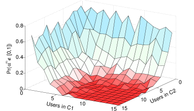
7.3.3 Impact of Cluster Composition
Under MaxRate scheduling, both user-based or cluster-based scheduling is throughput-optimal. However, the advantage of clustering is twofold: opportunistic cluster head selection yields higher channel qualities used to transmit in the system, which contributes to equalize transmission rates among connections (note that efficiency curves increase logarithmically according to Shannon’s results); and clustering offers the possibility to re-distribute the throughput among cluster members, thus yielding potentially higher fairness levels. We exemplify this effects by considering the specific case of MaxRate-MaxFair with two clusters. Each cluster can be regarded as a single connection, and the exact analysis of Subsection 7.3.2 applies.
Figure 7.1, which is the result of random instances for two clusters of random size and composition, is in line with our intuition on the effect of cluster size on . The figure shows the probability that be outside the acceptable range , when the perfect fairness can not be achieved. The figure reveals that perfect fairness can be achieved almost surely when both clusters consist of more than users. The probability of fairness non-achievability radically increases as the cluster size drops below users, since the average cluster qualities can be very unbalanced and yield large . In contrast, when clusters are large enough (i.e., with members), the fact that each cluster head exhibits the highest SNR in its cluster makes the probability to use the best MCS practically , and thus approximates , while increasing the probability of ties. Therefore, condition (7.17) is met with high probability.
7.3.4 How Much Throughput Lies in Ties?
In previous sections, we observed that providing fairness by leveraging scheduling ties can be challenging and complex. Now the question remains: is there enough gain in smart tie-breaking to justify the complexity? In order to answer this question, we setup a measurement campaign with mobile users that are subscribed to the same service provider and spread over an area of m2. We use an android application (i.e., G-MoN111http://www.wardriving-forum.de/wiki/G-MoN) to record the channel qualities of the smartphones in short intervals (one second) during a working day at the office. Note that given the good coverage in our premises, the users generally experience high channel quality in this experiment. Figure 7.2 illustrates the results of our measurements. We can observe the pdf of having ties of different size in Figure 7.2(a) (e.g., when there is no tie and for a tie between two users). The results show that with a probability, there is a tie between at least two users in the network. This is a motivating observation that highlights the significance of ties in cellular networks. Next, Figure 7.2(b) shows the pdf of the ties versus the MCS in which a tie occurs. Again, the measurements reveal that the majority of the ties occur in high MCS levels where there is higher throughput in ties.
In order to observe the impact of clustering, we divided the users into five clusters (i.e., users in each cluster) based on their physical proximity. In this experiment, we fed the same measurements into a script which applies the aforementioned clustering concept on the traces. In particular, the script looks at the traces of each cluster at each time interval and assigns the user with the highest MCS as the cluster head. Figure 7.3 is produced using the results obtained from the clustering script that demonstrates impact of clustering. It can be seen in Figure 7.3(a) that clustering significantly increases the probability of having ties. Moreover, the MCS in which a tie occurs is shifted to the right which maximizes the throughput in ties (see Figure 7.3(b)).
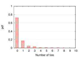
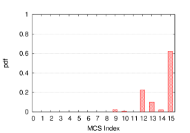
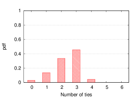
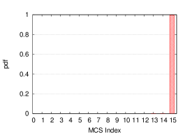
7.4 Heuristics to Achieve Maximal Fairness with MaxRate Scheduling of Multiple Connections
Having developed fundamental intuition based on exact results for the case of two connections, we now set out to design MaxRate schedulers for generic number of connections N in a set , achieving better fairness than with randomized tie-breaking. Note that, as discussed in Section 7.3.1, extending the analytical approach from the two-connection case would require tie-breaking parameters for all possible ties of connections, which grows too fast to be implementable (). Instead, we focus on scalable solutions that rely on at most tie-breaking parameters.
7.4.1 WRR Tie-breaking
We design a scheduler in which tie-breaking is resolved as if Weighted Round Robin (WRR) was implemented. Thus, we assume that for each connection there is a non-negative parameter used as follows.
Definition 5.
(WRR Tie-breaking) If, at a given scheduling epoch , is the set of connections that are currently tied in the highest MCS (see Definition 1), then the probability (or, the average fraction of time) that connection is served in such situations is as follows:
| (7.20) |
The expected throughput of connection under MaxRate with WRR tie-breaking is then:
| (7.21) |
where denotes any set of connections that includes .
Using (7.21) it is, however, intractable to obtain values of which would equalize the expected individual throughput of all connections, since it leads to a system of non-linear equations. Hence, in the following we propose heuristics to obtain .
7.4.1.1 Heuristic 1: Best Leaf First (BeLF)
This method is based on the results of the two-connection case, and on the use of binary trees. We have shown in Section 7.3.2 the exact way to compute for two connections in a tie. Now, two connections can represent two mobile users, as well as two clusters. More in general, the approach of Section 7.3.2 is valid for any two groups of users for which an SNR CDF is available to compute the probabilities to use the various MCS values. Therefore, we can use the results presented in Section 7.3.2 to compute the optimal tie-breaking probability for any two disjoint and not empty user groups covering the entire set , say subsets and , , . Let us call and the tie-breaking probabilities of and , respectively. These priorities are computed as per Eqs. (7.18) and (7.19) given in Definition 4. Any of the subsets grouping at least two users can be further split into two subsets, e.g., if , , for which , . To these smaller subsets, we can associate again two tie-breaking probabilities and , computed as per Definition 4. Each subset with at least two users can be recursively split into two subsets, and each subset receives a tie-breaking probability , where is the level of recursion, and is a sequential index within a recursion level. This binary splitting procedure can be represented with a binary tree, as shown in Figure 7.4(a). The tree root represents the entire network , and its tie-breaking probability is formally set to . Leaves represent connections (either individual mobile users or clusters), and each node at level in the tree represents the group of connections that appear as leaves in the branches originating at that node. We finally associate a WRR priority to each of the leaves of the tree: since each represents a conditional tie-breaking probability (given that there is a tie between two groups), the WRR priority of a connection is computed from the corresponding leaf as the product of the values on the path from the root to the leaf. With the above procedure, the sum of WRR priorities is exactly , so that they can be directly interpreted as tie-breaking probabilities for a multi-connection case.
The proposed heuristic might not work well when two leaves in the same branch are associated to users with very different average channel qualities, e.g., in very heterogeneous network conditions. This effect is due to the adoption of an expression similar to Eq. (4) for the computation of the SNR CDF associated to a node in the tree, i.e., the SNR of a node in the tree corresponds to the highest SNR among the users (leaves) connected to that node. In particular, at a given node of the binary tree, the presence of a branch without users with statistically good channel, namely good users, is kept “hidden” by the presence of another branch departing from the same node in which good users are present. Thus, qualitatively speaking, the grouping mechanism described here fails in distinguishing groups that differ in the number of poorly performing members.
7.4.1.2 Heuristic 2: Worst Leaf First (WoLF)
The previous discussion suggests an alternative way of building priorities by means of a binary tree. In particular, one could proceed as for the BeLF heuristic, but consider each node in the tree as a group represented by the worst channel quality among all users associated to leaves on the branches originating at that node (see Figure 7.4(b)). Therefore, the presence of a user with statistically poor channel on a leaf provokes a shift in the distribution of priorities towards the branch that contains that user.
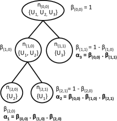
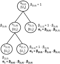
7.4.1.3 Heuristic 3: Fair Individual Share (FISh)
To compute for each connection in the system as the of a two-connection system (see Eq. (7.18)) in which connection competes with the rest of connections. In this case, we assume that the target of connection is to achieve a portion of the cell throughput.
Following the ideas from the two-connection case, we first define as the CDF for the best MCS of all the connections except connection , , and as the probability that at least one of the connections (except connection ) is in MCS and no other connection is in a better MCS, formally, . Then, (7.14) to (7.16) can be rewritten as follows, for :
| (7.22) | ||||
| (7.23) | ||||
| (7.24) |
The total cellular throughput of MaxRate is , which is the same for all values of , as it can be easily verified.
Proposition 15.
The MaxRate scheduler for a system with connections can achieve both one-slot and time-average fairness if and only if
| (7.25) |
The value of the tie-breaking probability is computed from the following equation:
| (7.26) |
The resulting value of is then:
| (7.27) |
However, when the expected transmission rate of connection is strictly higher than the average fair individual share (i.e., ), then is negative, which is not acceptable for the WRR scheduling mechanism. This corresponds to a situation in which the amount of resources in ties are not enough to equalize the connection throughputs without loss of throughput maximality. Therefore, we propose the following transformation which preserves the order of , i.e., preserves the priority list among connections:
| (7.28) |
Note that, since we use values as described in (7.20), the proposed transformation is equivalent to normalizing the values of in the interval , as if using . We remark that, in practice, we do not need to enforce any transformation if some , since WRR normalizes such values.
7.4.1.4 Heuristic 4: Priority Keying (PIKe)
Forcing the values in the interval might result in one or more connections not benefitting from tie-breaking at all (i.e., connections with ). However, considering that represents the excess throughput received by connection , setting should be allowed only for connections receiving more than the fair share, i.e., connections for which . Therefore, we propose a modified version of FISh, namely PIKe, in which priorities are shifted only if negative values are present:
| (7.29) |
As for the case of FISh, the proposed transformation is equivalent to normalizing the values of in the interval . However, the transformation is operated only when there exist negative values of .
In Section 7.5, we will quantify the level of fairness achieved in the system with the four proposed heuristics. We will also show that, on average, the PIKe heuristic performs better than the others. Although we will use static clustering scenarios to illustrate the advantages of our proposal, we remark that our methodology and findings apply to clusters whose composition varies in time, as some users may turn on/off their devices or migrate to another cluster or another cell. In particular, we note that in presence of flows with limited duration, probabilities described in Session 7.2 can be adapted to represent the steady-state probabilities of flow given the arrival and flow-size distributions.


7.4.2 Impact of Clustering on WRR Tie-breaking with Multiple Connections
Perfect fairness could be impossible to achieve under MaxRate scheduling due to the heterogeneity of user’s channel qualities (see Propositions 11 to 14). However, as mentioned earlier, clustering enough users, i.e., as few as mobile users, in practice, causes a very high probability to use the highest MCS value only. Therefore, clustering reduces the heterogeneity of the channel quality as observed by a scheduled connection (i.e., a cluster head).
To appreciate the impact of channel heterogeneity and clustering on a system with multiple connections, we depict in Figures 7.6 and 7.6 the probability to achieve perfect fairness as a function of connection quality distribution and cluster size, for a variable number of connections in the system. Figure 7.6 shows simulation results using the MaxRate scheduler when the mean SNR of user is picked from a uniform distribution.
Different intervals for are considered in the figure, to show the impact of different degrees of channel heterogeneity. For each interval of , we tested random instances of connections, and checked whether any tie-breaking strategy could lead to perfect fairness or not (brute force search of the optimal tie-breaking). Observing Figure 7.6, we can deduce that, depending on the interval in which the mean SNR can range, having a few tens of users in the cell can enable perfect fairness via tie-breaking. However, under typical heterogeneous conditions, in which the range for the mean SNR is several dB units, the probability to achieve perfect fairness is almost zero even when the number of users per cell is very high. Therefore, reducing heterogeneity in channel qualities is key to achieve fairness.
The impact of clustering on such quality heterogeneity is shown in Figure 7.6 for large levels of heterogeneity (). The Figure illustrates that clustering heterogenous users results in increased probability to achieve perfect fairness under MaxRate scheduling.
Notably, not using clustering makes the probability to achieve fairness practically negligible (see Figure 7.6 when Cluster size is ). In contrast, using small clusters (as few as users) dramatically increases the probability to achieve perfect fairness from to or more when the number of users in the cell ranges from to . Larger cluster sizes (e.g., or ) further boost perfect fairness achievability to or with a reasonable number of users in the system. Therefore, the potential impact of clustering on the fairness performance is paramount.
7.5 Evaluation
In this section, we validate via numerical evaluation of our D2D-based cluster scheduling proposals. We use the Jain’s fairness index to compare the effectiveness of our D2D-based schemes as compared to ET and PF scheduling with unclustered mobile users. As for the throughput, we normalize throughput results in terms of cell capacity. Since our work does not investigate intra-cluster mechanisms, assume that the total cluster throughput can be equally shared among cluster members, using cooperative D2D communications. PF performance figures are obtained by simulating a scheduling process in which the average user throughput is computed with an autoregressive filter with exponential time constant equal to frames. However results computed with time constant in the range to do not significantly differ.
For the sake of tractability, in what follows we assume that mobile users belong to one of three predefined SNR classes, which correspond to poor, average, and good average SNR, i.e., set contains three elements only. The designated average SNR for different classes are chosen in a manner that the mean achievable rates for poor, average, and good users are , , and of the maximum transmission rate achievable in the system, respectively. Therefore, with the MCS values reported in Table 1 and the assumed Rayleigh fading model, the average SNR values to be used in Eq. (2) for poor, average and good users are , respectively.
7.5.1 Impact of Clustering on System Performance
The potential clustering gain versus the conventional cellular architecture is discussed here. First, we illustrate the incentive for clustering with simple numerical calculations that show the average clustering gain. We assume that MaxRate schedules clusters and breaks ties at random (i.e., any cluster/connection has the same probability to be selected when a tie occurs). We refer to this particular version of MaxRate as MR. Second, we evaluate throughput and fairness performance. We evaluate the impact of clustering against two baseline schedulers. The first scheduler is Equal Time (ET), a simple and largely deployed round robin scheduler which guarantees the same fraction of airtime to each user. The second scheduler that we consider here is PF. In the figures presented in this subsection, results are averaged over random instances, and user qualities are uniformly distributed among poor, average, and good.
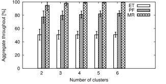
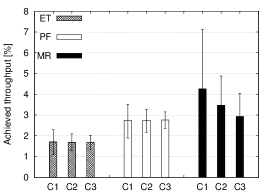
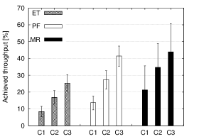
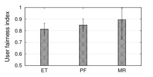
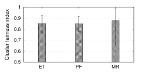
For reference, Figure 7.7 shows the difference in throughput achieved by ET, PF and MR schedulers as a function of the number of clusters in the network. Cluster sizes are chosen at random, ranging uniformly from to members. Of course, the throughput of ET and PF only depends on the number of mobile users and their channel qualities, but we keep using the number of clusters as reference. Interestingly, MR can double the throughput of ET and outperform PF by more than . Most importantly, MR can nearly achieve of the achievable throughput.
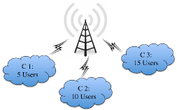
We now zoom into the performance experienced in the different clusters. Specifically, we consider a fixed topology, which is the simple one depicted in Figure 7.10. Clusters C, C and C share the same base station and have , and mobile users, respectively. Figure 7.8(a) shows the average throughput achieved by mobile users belonging to different clusters. The aggregate throughput per cluster is shown in Figure 7.8(b). For reference, Figure 7.8 also reports the throughput achieved with ET and PF schedulers without clustering (per-cluster throughput is then computed as the sum of throughputs achieved by each member separately). The high variability exhibited by MR is a drawback due to its greedy behavior (i.e., its random tie-breaking strategy), and to the occurrence of unbalanced clusters in our simulations (e.g., clusters with only good users will achieve extremely high throughput as compared to clusters with only poor users). Furthermore, clustering helps in terms of user fairness, as shown in Figure 7.9(a), where the Jain’s fairness index [177] among users is graphically depicted. As it can be seen in the figure, ET and PF are both outperformed by MR both in terms of per-user and per-cluster fairness. In practice, not only MR exhibits the highest throughput by far, but it also reduces unfairness. However, the variability shown by a pure MaxRate approach with random tie-breaking (MR) is high, which means there are great potentials for improvements. We next evaluate tie-breaking alternatives to further improve fairness.
7.5.2 Mapping Clusters to Leaves in BeLF and WoLF
Before proceeding with the full evaluation of the heuristics proposed in Section 7.4, let us recall that in our binary tree-based schemes, BeLF and WoLF, the leaves represent the entities to be scheduled. In principle, the order in which leaves in the binary tree are associated to connections (either users or clusters) is not necessarily related to topological considerations. In fact, nodes represent fictitious groups, not necessarily clusters. The only aim of defining fictitious groups consists in allowing a simple computation of WRR tie-breaking priorities for the real entities to be scheduled. However, the way in which connections are grouped in the binary tree affects the achieved fairness level.


Let us refer to connections as clusters, and associate each cluster with a goodness metric, which consist in counting the number of good users first, then the number of average users and eventually the number of poor users. Using this metric in our simulations, we have noticed that the highest fairness is achieved under one of two particular mappings. The first is a lexicographic mapping, i.e., connections are sorted from the best to the worst, and mapped in this order onto the leaves of the tree, from left to right. The second mapping consists in sorting connections according to an alternating order, i.e., the best connection first, then the worst, then the second best, followed by the second worst, and so on. Figures 7.11(a) and 7.11(b) depict two examples of CDF of the difference in Jain’s indexes achieved by lexicographic and alternating mappings, respectively and . Figure 7.11(a) shows that with connections both BeLF and WoLF yield better results with the lexicographic mapping. In contrast, Figure 7.11(b) shows that when the number of connections increases to , it is not clear which mapping is better, even though the difference is quite limited with very high probability (the CDF grows quite sharply around ).
However, since we are interested in the potential performance of D2D-based clustering systems, in the following, in order to compare BeLF and WoLF to the other proposed schemes, we will show results computed with the best mapping of clusters to tree leaves, which we found by testing all possible permutations.
7.5.3 Comparison of the Heuristics for MaxRate with WRR Tie-breaking
We now compare our proposed MaxRate variants based on the four heuristics introduced to compute the weights for the WRR tie-breaking. Specifically, we compare BeLF, WoLF, FISh, and PIKe in terms of per-cluster fairness. As a reference, we report the fairness indexes achieved by a plain MaxRate scheme where ties between connections are broken randomly (MR in the figures). We also compare results achieved by ET and PF. Note that, according to the common understanding, PF should have much higher fairness than MaxRate-based approaches [178], while we show that the opposite is true under cooperative D2D communications approaches, in which connections represent clusters. For ET and PF, we numerically simulate the scheduling of single users, then we sum up the throughput of users according to which cluster they belong to.
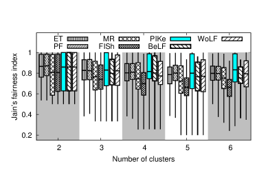
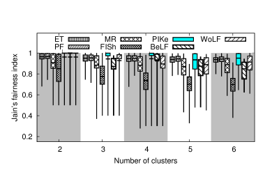
Figure 7.12 reports fairness indexes for the different scheduling schemes for systems with to clusters, each formed by to members. Fairness indexes are shown in terms of box and whiskers plots, reporting minimum and maximum values recorded over the set of simulations performed, the and percentiles of their values, and the average (the solid dashes in the boxes reported in the figure). Interestingly, the level of fairness achieved by our proposed schemes is very high, and PIKe achieves as much fairness as PF. Recalling that the throughput achieved by PF is much lower than the one achieved by PIKe, this result is very encouraging.
Even more interestingly, simulations accounting for clusters of at least users reveal that PIKe can outperform ET and PF in terms of fairness, as depicted in Figure 7.13, where the boxes delimited by the and percentiles are very close to for the PIKe scheme.
Figures 7.12 and 7.13 show that PIKe, BeLF, and WoLF clearly outperform the MR cluster scheduler, which justifies the work carried out in this manuscript. Comparing MR and PIKe, it can be seen that PIKe reduces the distance from perfect fairness (i.e., ) by . Note also that FISh achieves significantly poorer performance than the benchmarking policies, especially as the number of clusters increases.
To conclude, we remark that our proposed schemes, and in particular PIKe, are beneficial for both throughput and fairness, which means that they would allow better worst-case performance in comparison to ET and PF. Indeed, Figure 7.14 shows that the minimum throughput received by a cluster member in the system, using PIKe, is much higher that the one achieved with ET (by a factor or more), and PF (by a factor ).
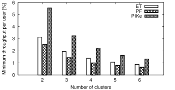
7.6 Summary
In this chapter, we have shown how to attain maximal throughput in cellular networks without paying any fairness penalty. Although scheduling ties are usually ignored and uniformly random tie-breaking is an accepted practice, we have shown that this practice is rather inefficient. Our simulations indicate that there is a great potential for fairness and throughput enhancements in customized tie-breaking as soon as tie probabilities become relevant, e.g., by using opportunistic clustering strategies. We have rigorously formulated a tie-breaking mechanism that achieves maximal fairness and maximal throughput. The complexity of the optimal approach is not tractable for more than two connections, so we have proposed PIKe, a heuristic inspired by the optimal solution for the case of connections. Our results confirm that PIKe achieves almost perfect fairness and maximal throughput and largely benefits of D2D-enabled opportunistic clustering schemes.
Chapter 8 Conclusions
This dissertation is dedicated to study and to explore different aspects of D2D communications in cellular networks. In Chapters 1 and 2, we provided the reader an introduction to D2D communications and opportunistic scheduling, and a thorough survey of the-state-of-the-art in the field. In our survey, we shed light on the open research problems in D2D communications, some of which are addressed in this dissertation. In Chapter 3, we proposed an opportunistic clustering scheme leveraging outband D2D communications and we provided a theoretical analysis of throughput and energy consumption of our proposal. In Chapter 4, we devised a protocol for our proposed architecture in Chapter 3. Chapter 5 elaborated our testbed setup and experimental evaluation of our proposal. In Chapter 6, we demonstrated the true potential of D2D communications when both inband and outband modes are present. In Chapter 7, we exploited D2D communications and smart tie-breaking techniques to achieve maximal fairness using MaxRate scheduling algorithm.
Our theoretical results illustrate that using simple schedulers and game theory approaches, our proposed architecture significantly outperforms legacy schedulers in terms of throughput, delay, energy efficiency, and fairness. In particular, our opportunistic scheme achieves up to % throughput gain and % energy efficiency gain with respect to legacy schemes. Our results also confirmed that our D2D-clustering scheme results in almost perfect user fairness. We also analyzed the practicality of implementing opportunistic D2D communications in cellular networks using WiFi Direct and LTE-A. Our proposed protocol proved that not only D2D-assisted cellular communications are practical, but also that they can be achieved with minimal modifications to the current architecture of LTE-A and WiFi Direct. We prototyped the first SDR platform for outband D2D communications. We leveraged Xilinx FPGAs and the NI Real-Time OS to develop realistic experiments with LTE-like millisecond CQI reporting, scheduling, and high-speed LTE-WiFi interaction. Our experimental evaluation using several QoS and QoE metrics confirms the feasibility and potentials of opportunistic outband D2D communications. In particular, we designed DORE which is a 3GPP ProSe-compliant and QoS-aware opportunistic outband D2D framework. The results reveal that experimental performance figures are lower than the reported values in the prior analytical studies, although still notable (up to % with just two users). Nevertheless, high throughput gains are achievable if the number of participating UEs in opportunistic outband D2D increases (up to % with five users).
We did not confine our research to a single D2D mode and we investigated the problem of D2D mode selection in a multimode D2D setup to better evaluate the true potential of D2D communications. We showed that the performance of D2D modes is highly scenario-dependent. To cope with this issue, we proposed the Floating Band D2D framework along with practical heuristics suitable for quick and adaptive mode selection in such a complex setup. Unlike existing schemes, we allow D2D users to communicate over inband or outband modes, depending on network load and channel conditions. Our results demonstrate the impressive potentials of multi-band mode selection. Remarkably, our simple heuristics result in fair operation and achieve near optimal performance by dramatically ameliorating network utility, which accounts for both throughput and energy consumption. In particular, we achieved up to % throughput gain in comparison to legacy cellular networks.
Finally, we showed that scheduling ties are significant but forgotten resources that can be exploited to reduce unfairness among mobile users. To this aim, we proposed novel solutions for leveraging the capabilities of D2D communications to achieve higher fairness without affecting the throughput optimality of MaxRate scheduler. We first analyzed the tie-breaking problem mathematically. Next, we designed smart tie-breaking mechanisms to exploit these ties to improve the fairness of MaxRate scheduler. Our evaluation results indicate that using D2D communications and smart tie-breaking, we ameliorate the network performance in terms of throughput and fairness.
Appendices
Appendix A
Proof of Proposition 3
Proof: In CLWRR, each cluster is scheduled with probability . When cluster is selected by the scheduler, its user with the highest SNR is actually scheduled. For each possible MCS , user is the one experiencing the highest SNR in its cluster with probability , . Since channels are independent, using the total probability formula yields . Given that represents the probability that cluster can be scheduled with the -th MCS, the result follows by applying again the total probability formula for the discrete set of MCS values.
Proof of Proposition 4
Proof: The proof is similar to the proof of Proposition 3. In CLMR, the scheduled cluster receives all resources , given that the cluster contains the user with the highest SNR in the system. For each possible MCS , cluster is the one containing the user experiencing the best SNR with probability , with , and . Since channels are independent, using the total probability formula yields . Given that represents the probability that cluster is scheduled with the -th MCS, with which the transmitted bits per symbol are , the result follows by applying the total probability formula for the discrete set of MCSs.
Proof of Proposition 6
Proof: In CLMR a user is scheduled when it has the highest SNR. Therefore, for each possible MCS , user is scheduled with probability , with . Since channels are independent, using the total probability formula yields . Given that represents the probability that user can be scheduled with the -th MCS, the result follows by applying the total probability formula for the discrete set of MCS values.
Proof of Proposition 9
Proof: Due to our stationary traffic and channel quality assumptions, the traffic distribution over a scheduling interval is the same as the long term distribution of throughputs within the cluster . Let us denote by the ratio between the user’s throughout and the total cluster throughput . Therefore, the traffic sent over WiFi, , is a fraction of the traffic received over the LTE interface by user , which yields Eq. (3.16) Similarly, the WiFi transmission data rate corresponds to a fraction of all the traffic delivered by LTE, when user is not the cluster head, which yields Eq. (3.17).
Proof of Proposition 10
Proof: is the sum of two terms: the probability that user is the cluster head and sends traffic to other cluster members, and the probability that user is not cluster head and receives its packets from the cluster head. Since such probabilities can be interpreted as the average fraction of time spent in either in reception or transmission over the WiFi interface, we have , which leads to the result.
Appendix B
Transmission Rates and Cluster MCS Selection
The instantaneous achievable rate of connection at slot , , depends on the adopted MCS . We assume that the actual MCS for connection at slot is selected as a function of the instantaneous SNR , i.e.:
| (1) | |||
Therefore, the probability that a scheduled connection receives data encoded according to the -th MCS is:
| (2) |
Table 1 shows a list of possible modulation and coding schemes for LTE-like networks [155], their coding rate, and the SNR threshold (in dB) that has to be reached to achieve a negligible error rate. The table also contains the net transmission rate, in bits per symbol, achieved with each MCS. The Implementation Margin (IM) in Table 1 is a value that represents the noise due to non-ideal receiver. In our simulation, MCS thresholds include both SNR and IM.
| Modulation | Coding | SNR | IM | SNR+IM | Bits per | |
| Rate | (dB) | (dB) | (dB) | symbol | ||
| QPSK | 1/8 | -5.1 | 2.5 | -2.6 | 0.25 | |
| 1/5 | -2.9 | -0.4 | 0.4 | |||
| 1/4 | -1.7 | 0.8 | 0.5 | |||
| 1/3 | -1 | 1.5 | 0.67 | |||
| 1/2 | 2 | 4.5 | 1 | |||
| 2/3 | 4.3 | 6.8 | 1.3 | |||
| 3/4 | 5.5 | 8.0 | 1.5 | |||
| 4/5 | 6.2 | 8.7 | 1.6 | |||
| 16QAM | 1/2 | 7.9 | 3 | 10.9 | 2 | |
| 2/3 | 11.3 | 14.3 | 2.66 | |||
| 3/4 | 12.2 | 15.2 | 3 | |||
| 4/5 | 12.8 | 15.8 | 3.2 | |||
| 64QAM | 2/3 | 15.3 | 4 | 19.3 | 4 | |
| 3/4 | 17.5 | 21.5 | 4.5 | |||
| 4/5 | 18.6 | 22.6 | 4.8 |
In our scheme, we adopt the MaxRate scheduling algorithm to maximize the utilization of cellular resources. The cluster that contains the user with the highest MCS is scheduled, so we propose to operate clusters in opportunistic way: the cluster head can change on a per-frame basis, as it is opportunistically selected as the cluster member with the highest current MCS rate; an entire cluster is scheduled as an individual user whose MCS is the highest among members; the cluster head relays the downlink packets to the final destination (intra-cluster communications) on a secondary wireless interface, using D2D communications. Therefore, in this work, a connection is a cluster (also indicated as CLn) composed by mobiles, and its instantaneous SNR is the highest SNR among the mobile users composing the cluster. In particular, the probability that a scheduled connection (i.e., cluster CLn) receives data encoded according to the -th MCS can be computed based on the SNR CDF and the MCS thresholds used in LTE, similarly to Eq.(2):
| (3) |
where is the CDF of the maximum of random variables representing the SNR values of each of the mobiles forming cluster CLn:
| (4) |
Proof of Proposition 11
Proof: Observe first that is the minimum achievable transmission rate for user under the MaxRate scheduler, since this user must be served if it has an MCS strictly better than the other user. Moreover, is the maximum achievable transmission rate for user under the MaxRate scheduler, since this user must be served if it has an MCS strictly better than the other user and, in addition, it can be served at most in all the ties. Then, fairness cannot be achieved if either or , which is equivalent to . In contrast, fairness can be achieved if (7.17) holds, as shown in (14). Therefore, the equivalence holds.
Proof of Proposition 12
Proof: Item 1) is a special case of item 2), which holds because
| (5) |
Item 3) can be proved as follows: is equivalent to , therefore by non-negativity of probabilities it is true that
| (6) |
By adding we have
| (7) |
By expanding and we further obtain
| (8) |
Realizing that the first sum equals , we have
| (9) |
For each , term since , therefore
| (10) |
Proof of Proposition 14
Proof: Consider the MaxRate scheduler with randomized tie-breaking with bias for user . Then, the expected time-average and one-slot individual throughputs are and , respectively. It is straightforward to verify that, if (7.17) holds, plugging for the throughput of each user is equal to .
References
- [1] A. Asadi and V. Mancuso, “A survey on opportunistic scheduling in wireless communications,” IEEE Communications Surveys & Tutorials, vol. 15, no. 4, pp. 1671–1688, 2013.
- [2] A. Asadi, Q. Wang, and V. Mancuso, “A survey on device-to-device communication in cellular networks,” IEEE Communications Surveys & Tutorials, vol. 16, no. 4, pp. 1801–1819, Fourthquarter 2014.
- [3] Y.-D. Lin and Y.-C. Hsu, “Multihop cellular: A new architecture for wireless communications,” in Proceedings of IEEE INFOCOM, vol. 3, 2000, pp. 1273–1282.
- [4] X. Wu, S. Tavildar, S. Shakkottai, T. Richardson, J. Li, R. Laroia, and A. Jovicic, “FlashLinQ: a synchronous distributed scheduler for peer-to-peer ad hoc networks,” IEEE/ACM Transactions on Networking, vol. 21, no. 4, pp. 1215–1228, 2013.
- [5] 3GPP TR 22.803, “Feasibility study for proximity services (ProSe) (release 12),” v. 12.2.0, 2013.
- [6] 3GPP TR 23.703, “Study on architecture enhancements to support proximity services (ProSe) (release 12),” v. 1.0.0, 2013.
- [7] 3GPP, “3GPP;Technical specification group services and system aspects; Proximity-based services (ProSe); Stage 2 (release 13),” TR 23.303 V13.0.0, 2015.
- [8] ——, “3GPP; technical specification group RAN; study on LTE device to device proximity services (ProSe) radio aspects (release 13),” TR 36.843 V12.0.1, 2015.
- [9] A. Asadi and V. Mancuso, “DRONEE: Dual-radio opportunistic networking for energy efficiency,” Computer Communications, vol. 50, pp. 41 – 52, 2014.
- [10] A. Asadi, V. Sciancalepore, and V. Mancuso, “On the efficient utilization of radio resources in extremely dense wireless networks,” IEEE Communications Magazine, vol. 53, no. 1, pp. 126–132, 2015.
- [11] A. Asadi and V. Mancuso, “WiFi Direct and LTE D2D in action,” in Proceedings of IFIP Wireless Days, 2013, pp. 1–8.
- [12] ——, “On the compound impact of opportunistic scheduling and D2D communications in cellular networks,” in Proceedings of ACM MSWIM, 2013, pp. 279–288.
- [13] M. I. Sanchez, A. Asadi, M. Draexler, R. Gupta, V. Mancuso, A. Morelli, A. De la Oliva, and V. Sciancalepore, “Tackling the increased density of 5G networks; the CROWD approach,” in Proceedings of 5GArch in conjunction with IEEE VTC, 2015.
- [14] R. Gupta, B. Bachmann, A. Kruppe, R. Ford, S. Rangan, N. Kundargi, A. Ekbal, K. Rathi, A. Asadi, V. Mancuso et al., “LabVIEW based software-defined Physical/MAC layer architecture for prototyping dense LTE networks,” in Proceedings of WInnComm, 2015.
- [15] C. Vitale, V. Sciancalepore, A. Asadi, and V. Mancuso, “Two-level opportunistic spectrum management for green 5G radio access networks,” in IEEE International Conference on Green Computing and Communications, 2015.
- [16] A. Asadi, V. Mancuso, and R. Gupta, “An SDR-based experimental study of outband D2D communications,” in IEEE INFOCOM, 2016.
- [17] A. Asadi and V. Mancuso, “Energy efficient opportunistic uplink packet forwarding in hybrid wireless networks,” in Proceedings of the fourth international conference on Future energy systems, 2013, pp. 261–262.
- [18] ——, “Energy efficient opportunistic uplink packet forwarding in hybrid wireless networks (poster),” in 5th IMDEA networks annual workshop, 2013.
- [19] A. Asadi, R. Gupta, and V. Mancuso, “An SDR-based experimental study of outband D2D communications (poster),” in 7th IMDEA networks annual workshop, 2015.
- [20] ——, “CROWD solutions for SDN-controlled SDR networks with D2D (demo),” in EUCNC, 2015.
- [21] A. Asadi, V. Mancuso, and P. Jacko, “Floating band D2D: Exploring and exploiting the potentials of adaptive D2D-enabled networks,” in Proceedings of IEEE WoWMoM, 2015, pp. 1–9.
- [22] A. Asadi, P. Jacko, and V. Mancuso, “Modeling multi-mode D2D communications in LTE,” in Proceedings of MAMA workshop in conjunction with ACM SIGMETRICS, 2014.
- [23] ——, “Modeling D2D communications with LTE and WiFi,” ACM SIGMETRICS Performance Evaluation Review, vol. 42, no. 2, pp. 55–57, 2014.
- [24] ——, “Mind the ties (poster),” in 6th IMDEA networks annual workshop, 2014.
- [25] R. Knopp and P. Humblet, “Information capacity and power control in single-cell multiuser communications,” in Proceedings of IEEE ICC, vol. 1, june 1995, pp. 331–335 vol.1.
- [26] P. Viswanath, D. Tse, and R. Laroia, “Opportunistic beamforming using dumb antennas,” in IEEE Transactions on Information Theory, June 2002, p. 449.
- [27] N. Sharma and L. Ozarow, “A study of opportunism for multiple-antenna systems,” IEEE Transactions on Information Theory, vol. 51, no. 5, pp. 1804 – 1814, May 2005.
- [28] X. Qin and R. Berry, “Exploiting multiuser diversity for medium access control in wireless networks,” in Proceedings of IEEE INFOCOM, vol. 2, 2003, pp. 1084–1094.
- [29] M. Andrews, K. Kumaran, K. Ramanan, A. Stolyar, R. Vijayakumar, and P. Whiting, “Scheduling in a queuing system with asynchronously varying service rates,” Probability in the Engineering and Informational Sciences, vol. 18, pp. 191–217, Apr. 2004.
- [30] P. van de Ven, S. Borst, and S. Shneer, “Instability of maxweight scheduling algorithms,” in Proceedings of IEEE INFOCOM, April 2009, pp. 1701 –1709.
- [31] J.-W. Lee, R. Mazumdar, and N. Shroff, “Opportunistic power scheduling for multi-server wireless systems with minimum performance constraints,” in Proceedings of IEEE INFOCOM, vol. 2, Mar. 2004, pp. 1067–1077 vol.2.
- [32] C. Wong, R. Cheng, K. Lataief, and R. Murch, “Multiuser OFDM with adaptive subcarrier, bit, and power allocation,” IEEE Journal on Selected Areas in Communications, vol. 17, no. 10, pp. 1747–1758, 1999.
- [33] M. Andrews and L. Zhang, “Scheduling algorithms for multi-carrier wireless data systems,” in Proceedings of ACM MobiCom. ACM, 2007, pp. 3 –14.
- [34] A. Lyapunov, “The general problem of the stability of motion,” International Journal of Control, vol. 55, no. 3, pp. 531–534, 1992.
- [35] S. Liu, L. Ying, and R. Srikant, “Throughput-optimal opportunistic scheduling in the presence of flow-level dynamics,” IEEE/ACM Transactions on Networking, vol. 19, no. 4, pp. 1057 –1070, August 2011.
- [36] ——, “Scheduling in multichannel wireless networks with flow-level dynamics,” in Proceedings of the ACM SIGMETRICS, 2010, pp. 191–202.
- [37] H. Al-Zubaidy, I. Lambadaris, and J. Talim, “Optimal scheduling in high-speed downlink packet access networks,” ACM Transactions on Modeling and Computer Simulation, vol. 21, pp. 3:1–3:27, December 2010.
- [38] W. Ouyang, S. Murugesan, A. Eryilmaz, and N. Shroff, “Exploiting channel memory for joint estimation and scheduling in downlink networks,” in Proceedings of IEEE INFOCOM, April 2011, pp. 3056 –3064.
- [39] P. Chaporkar, A. Proutiere, H. Asnani, and A. Karandikar, “Scheduling with limited information in wireless systems,” in Proceedings of ACM MobiHoc, 2009, pp. 75–84.
- [40] M. Ouyang and L. Ying, “On optimal feedback allocation in multichannel wireless downlinks,” in Proceedings of ACM MobiHoc. ACM, 2010, pp. 241–250.
- [41] P. Jacko, “Value of information in optimal flow-level scheduling of users with Markovian time-varying channels,” Journal of Performance Evaluation, vol. 68, no. 11, pp. 1022–1036, November 2011.
- [42] C. Luo, F. R. Yu, H. Ji, and V. C. Leung, “Optimal channel access for TCP performance improvement in cognitive radio networks,” Wireless Networks, vol. 17, pp. 479–492, February 2011.
- [43] K. Khalil, M. Karaca, O. Ercetin, and E. Ekici, “Optimal scheduling in cooperate-to-join cognitive radio networks,” in Proceedings of IEEE INFOCOM, April 2011, pp. 3002 –3010.
- [44] H. Kim and G. de Veciana, “Losing opportunism: Evaluating service integration in an opportunistic wireless system,” in Proceedings of IEEE INFOCOM, May 2007, pp. 982 –990.
- [45] S. Patil and G. de Veciana, “Managing resources and quality of service in heterogeneous wireless systems exploiting opportunism,” IEEE/ACM Transactions on Networking, vol. 15, no. 5, pp. 1046 –1058, October 2007.
- [46] ——, “Reducing feedback for opportunistic scheduling in wireless systems,” IEEE Transactions on Wireless Communications, vol. 6, no. 12, pp. 4227 –4232, December 2007.
- [47] S. Shakkottai, “Effective capacity and QoS for wireless scheduling,” IEEE Transactions on Automatic Control, vol. 53, no. 3, pp. 749 –761, April 2008.
- [48] P. Key, L. Massoulie, A. Bain, and F. Kelly, “Fair internet traffic integration: Network flow models and analysis,” Annals of Telecommunications, vol. 59, pp. 1338–1352, 2004.
- [49] E. Altman, A. Orda, and N. Shimkin, “Bandwidth allocation for guaranteed versus best effort service categories,” in Proceedings of IEEE INFOCOM, vol. 2, March 1998, pp. 617 –624 vol.2.
- [50] T.-J. Lee and G. de Veciana, “Model and performance evaluation for multiservice network link supporting ABR and CBR services,” IEEE Communications Letters, vol. 4, no. 11, pp. 375 –377, November 2000.
- [51] M. Neely, “Opportunistic scheduling with worst case delay guarantees in single and multi-hop networks,” in Proceedings of IEEE INFOCOM, April 2011, pp. 1728 –1736.
- [52] K. W. Choi, W. S. Jeon, and D. G. Jeong, “Resource allocation in OFDMA wireless communications systems supporting multimedia services,” IEEE/ACM Transactions on Networking, vol. 17, no. 3, pp. 926 –935, June 2009.
- [53] S. Borst and P. Whiting, “Dynamic channel-sensitive scheduling algorithms for wireless data throughput optimization,” IEEE Transactions on Vehicular Technology, vol. 52, no. 3, pp. 569 – 586, May 2003.
- [54] M. Andrews, K. Kumaran, K. Ramanan, A. Stolyar, P. Whiting, and R. Vijayakumar, “Providing quality of service over a shared wireless link,” IEEE Communications Magazine, vol. 39, no. 2, pp. 150 –154, February 2001.
- [55] B. Sadiq, S. J. Baek, and G. de Veciana, “Delay-optimal opportunistic scheduling and approximations: The Log rule,” in Proceedings of IEEE INFOCOM, April 2009, pp. 1692 –1700.
- [56] R. K. Beidokhti, M. H. Yaghmaee Moghaddam, and J. Chitizadeh, “Adaptive QoS scheduling in wireless cellular networks,” Wireless Networks, vol. 17, pp. 701–716, April 2011.
- [57] R. Jain, D. Chiu, and W. Hawe, “A quantitative measure of fairness and discrimination for resource allocation in shared computer systems,” DEC research report TR-301, 1984.
- [58] Z. Zhang, Y. He, and E. Chong, “Opportunistic downlink scheduling for multiuser OFDM systems,” in Proceedings of IEEE WCNC, vol. 2. IEEE, 2005, pp. 1206–1212.
- [59] X. Liu, E. Chong, and N. Shroff, “A framework for opportunistic scheduling in wireless networks,” Computer Networks, vol. 41, no. 4, pp. 451–474, 2003.
- [60] H. Kuhn, “The Hungarian method for the assignment problem,” Naval research logistics quarterly, vol. 2, no. 1-2, pp. 83–97, 1955.
- [61] E. Liu and K. Leung, “Proportional fair scheduling: Analytical insight under Rayleigh fading environment,” in Proceedings of IEEE WCNC, 2008, pp. 1883–1888.
- [62] J. Yang, Z. Yifan, W. Ying, and Z. Ping, “Average rate updating mechanism in proportional fair scheduler for HDR,” in Proceedings of IEEE GLOBECOM, vol. 6, 2004, pp. 3464–3466.
- [63] R. Almatarneh, M. Ahmed, and O. Dobre, “Performance analysis of proportional fair scheduling in OFDMA wireless systems,” in Proceedings of IEEE Vehicular Technology Conference (VTC), 2010, pp. 1–5.
- [64] Z. Shen, J. Andrews, and B. Evans, “Adaptive resource allocation in multiuser OFDM systems with proportional rate constraints,” IEEE Transactions on Wireless Communications, vol. 4, no. 6, pp. 2726–2737, 2005.
- [65] J.-A. Kwon, B.-G. Kim, and J.-W. Lee, “A unified framework for opportunistic fair scheduling in wireless networks: A dual approach,” Wireless Networks, vol. 16, pp. 1975–1986, October 2010.
- [66] D. Bertsekas, A. Nedi, A. Ozdaglar et al., Convex analysis and optimization. Athena Scientific, 2003.
- [67] D. Bertsekas, Nonlinear programming. Athena Scientific, 1999.
- [68] X. Tang, S. Ramprashad, and H. Papadopoulos, “Multi-cell user-scheduling and random beamforming strategies for downlink wireless communications,” in Proceedings of IEEE VTC, September 2009, pp. 1 –5.
- [69] M. Kountouris and D. Gesbert, “Memory-based opportunistic multi-user beamforming,” in Proceedings of IEEE International Symposium on Information Theory, September 2005, pp. 1426 –1430.
- [70] R. Bendlin, Y.-F. Huang, M. Ivrlac, and J. Nossek, “Fast distributed multi-cell scheduling with delayed limited-capacity backhaul links,” in Proceedings of IEEE ICC, June 2009, pp. 1 –5.
- [71] IEEE, “Standard 802.16e-2005. part16: Air interface for fixed and mobile broadband wireless access systems: Amendment for physical and medium access control layers for combined fixed and mobile operation in licensed band,” 2005.
- [72] 3GPP, “Physical layer procedures (release 10) for evolved universal terrestrial radio access (E-UTRA),” 3GPP TS 36.213 v 10.5.0, 2012.
- [73] B. Kaufman and B. Aazhang, “Cellular networks with an overlaid device to device network,” in Proceedings of Asilomar Conference on Signals, Systems and Computers, 2008, pp. 1537–1541.
- [74] K. Doppler, M. Rinne, C. Wijting, C. Ribeiro, and K. Hugl, “Device-to-device communication as an underlay to LTE-advanced networks,” IEEE Communications Magazine, vol. 47, no. 12, pp. 42–49, 2009.
- [75] K. Doppler, M. P. Rinne, P. Janis, C. Ribeiro, and K. Hugl, “Device-to-device communications; functional prospects for LTE-Advanced networks,” in Proceedings of IEEE ICC Workshops, 2009, pp. 1–6.
- [76] A. Osseiran, K. Doppler, C. Ribeiro, M. Xiao, M. Skoglund, and J. Manssour, “Advances in device-to-device communications and network coding for IMT-Advanced,” ICT Mobile Summit, 2009.
- [77] T. Peng, Q. Lu, H. Wang, S. Xu, and W. Wang, “Interference avoidance mechanisms in the hybrid cellular and device-to-device systems,” in Proceedings of IEEE PIMRC, 2009, pp. 617–621.
- [78] J. Du, W. Zhu, J. Xu, Z. Li, and H. Wang, “A compressed HARQ feedback for device-to-device multicast communications,” in Proceedings of IEEE VTC-Fall, 2012, pp. 1–5.
- [79] B. Zhou, H. Hu, S.-Q. Huang, and H.-H. Chen, “Intracluster device-to-device relay algorithm with optimal resource utilization,” IEEE Transactions on Vehicular Technology, vol. 62, no. 5, pp. 2315–2326, Jun. 2013.
- [80] L. Lei, Z. Zhong, C. Lin, and X. Shen, “Operator controlled device-to-device communications in LTE-Advanced networks,” IEEE Wireless Communications, vol. 19, no. 3, pp. 96–104, 2012.
- [81] N. Golrezaei, A. F. Molisch, and A. G. Dimakis, “Base-station assisted device-to-device communications for high-throughput wireless video networks,” in Proceeding of IEEE ICC, 2012.
- [82] N. Golrezaei, A. G. Dimakis, and A. F. Molisch, “Device-to-device collaboration through distributed storage,” in Proceeding of IEEE GLOBECOM, 2012, pp. 7077–7081.
- [83] J. C. Li, M. Lei, and F. Gao, “Device-to-device (D2D) communication in MU-MIMO cellular networks,” in Proceedings of IEEE GLOBECOM, 2012, pp. 3583–3587.
- [84] N. K. Pratas and P. Popovski, “Low-rate machine-type communication via wireless device-to-device (D2D) links,” arXiv preprint, 2013.
- [85] X. Bao, U. Lee, I. Rimac, and R. R. Choudhury, “DataSpotting: Offloading cellular traffic via managed device-to-device data transfer at data spots,” ACM SIGMOBILE Mobile Computing and Communications Review, vol. 14, no. 3, pp. 37–39, 2010.
- [86] X. Lin, J. G. Andrews, A. Ghosh, and R. Ratasuk, “An overview of 3GPP device-to-device proximity services,” IEEE Communications Magazine, vol. 52, no. 4, pp. 40–48, 2014.
- [87] C.-H. Yu, K. Doppler, C. Ribeiro, and O. Tirkkonen, “Performance impact of fading interference to device-to-device communication underlaying cellular networks,” in Proceedings of IEEE PIMRC, 2009, pp. 858–862.
- [88] C. Xu, L. Song, Z. Han, Q. Zhao, X. Wang, and B. Jiao, “Interference-aware resource allocation for device-to-device communications as an underlay using sequential second price auction,” in Proceedings of IEEE ICC, 2012, pp. 445–449.
- [89] S. Xu, H. Wang, T. Chen, Q. Huang, and T. Peng, “Effective interference cancellation scheme for device-to-device communication underlaying cellular networks,” in Proceedings of IEEE VTC-Fall, 2010, pp. 1–5.
- [90] W. Xu, L. Liang, H. Zhang, S. Jin, J. C. Li, and M. Lei, “Performance enhanced transmission in device-to-device communications: Beamforming or interference cancellation?” in Proceedings of IEEE GLOBECOM, 2012, pp. 4296–4301.
- [91] R. Zhang, X. Cheng, L. Yang, and B. Jiao, “Interference-aware graph based resource sharing for device-to-device communications underlaying cellular networks,” in Proceedings of IEEE WCNC, 2013, pp. 140–145.
- [92] P. Janis, V. Koivunen, C. Ribeiro, J. Korhonen, K. Doppler, and K. Hugl, “Interference-aware resource allocation for device-to-device radio underlaying cellular networks,” in Proceedings of IEEE VTC-Spring, 2009, pp. 1–5.
- [93] H. Min, J. Lee, S. Park, and D. Hong, “Capacity enhancement using an interference limited area for device-to-device uplink underlaying cellular networks,” IEEE Transactions on Wireless Communications, vol. 10, no. 12, pp. 3995–4000, December 2011.
- [94] H. E. Elkotby, K. M. Elsayed, and M. H. Ismail, “Exploiting interference alignment for sum rate enhancement in D2D-enabled cellular networks,” in Proceedings of IEEE WCNC, 2012, pp. 1624–1629.
- [95] Y. Pei and Y.-C. Liang, “Resource allocation for device-to-device communication overlaying two-way cellular networks,” IEEE Transactions on Wireless Communications, vol. 12, no. 7, pp. 3611–3621, Jul. 2013.
- [96] WiFi Alliance, “Wi-Fi peer-to-peer (P2P) technical specification v1.2,” 2013.
- [97] Bluetooth SIG, “Bluetooth specification version 1.1,” Available at http://www.bluetooth.com, 2001.
- [98] Q. Wang and B. Rengarajan, “Recouping opportunistic gain in dense base station layouts through energy-aware user cooperation,” in Proceedings of IEEE WoWMoM, 2013, pp. 1–9.
- [99] K. Akkarajitsakul, P. Phunchongharn, E. Hossain, and V. K. Bhargava, “Mode selection for energy-efficient D2D communications in LTE-advanced networks: A coalitional game approach,” in Proceedings of IEEE ICCS, 2012, pp. 488–492.
- [100] ZigBee Alliance, “Zigbee specification,” Document 053474r06, Version, vol. 1, 2006.
- [101] M. Jung, K. Hwang, and S. Choi, “Joint mode selection and power allocation scheme for power-efficient device-to-device (D2D) communication,” in Proceedings of IEEE VTC-Spring, 2012, pp. 1–5.
- [102] S. Hakola, T. Chen, J. Lehtomaki, and T. Koskela, “Device-to-device (D2D) communication in cellular network-performance analysis of optimum and practical communication mode selection,” in Proceedings of IEEE WCNC, 2010, pp. 1–6.
- [103] L. Su, Y. Ji, P. Wang, and F. Liu, “Resource allocation using particle swarm optimization for D2D communication underlay of cellular networks,” in Proceedings of IEEE WCNC, 2013, pp. 129–133.
- [104] J. Kennedy, “Particle swarm optimization,” in Encyclopedia of Machine Learning. Springer, 2010, pp. 760–766.
- [105] M.-H. Han, B.-G. Kim, and J.-W. Lee, “Subchannel and transmission mode scheduling for D2D communication in OFDMA networks,” in Proceedings of IEEE VTC-Fall, 2012, pp. 1–5.
- [106] X. Chen, L. Chen, M. Zeng, X. Zhang, and D. Yang, “Downlink resource allocation for device-to-device communication underlaying cellular networks,” in Proceedings of IEEE PIMRC, 2012, pp. 232–237.
- [107] C.-H. Yu and O. Tirkkonen, “Device-to-device underlay cellular network based on rate splitting,” in Proceedings of IEEE WCNC, 2012, pp. 262–266.
- [108] K. Doppler, C.-H. Yu, C. Ribeiro, and P. Janis, “Mode selection for device-to-device communication underlaying an LTE-Advanced network,” in Proceedings of IEEE WCNC, 2010, pp. 1–6.
- [109] M. Zulhasnine, C. Huang, and A. Srinivasan, “Efficient resource allocation for device-to-device communication underlaying LTE network,” in IEEE WiMob, 2010, pp. 368–375.
- [110] Z. Liu, T. Peng, H. Chen, and W. Wang, “Optimal D2D user allocation over multi-bands under heterogeneous networks,” in Proceedings of IEEE GLOBECOM, 2012, pp. 1339–1344.
- [111] C. Xu, L. Song, Z. Han, D. Li, and B. Jiao, “Resource allocation using a reverse iterative combinatorial auction for device-to-device underlay cellular networks,” in Proceedings of IEEE GLOBECOM, 2012, pp. 4542–4547.
- [112] X. Xiao, X. Tao, and J. Lu, “A QoS-aware power optimization scheme in OFDMA systems with integrated device-to-device (D2D) communications,” in Proceedings of IEEE VTC-Fall, 2011, pp. 1–5.
- [113] M. Belleschi, G. Fodor, and A. Abrardo, “Performance analysis of a distributed resource allocation scheme for D2D communications,” in Proceedings of IEEE GLOBECOM Workshops, 2011, pp. 358–362.
- [114] C.-H. Yu, O. Tirkkonen, K. Doppler, and C. Ribeiro, “Power optimization of device-to-device communication underlaying cellular communication,” in Proceedings of IEEE ICC, 2009, pp. 1–5.
- [115] D. Feng, L. Lu, Y. Yuan-Wu, G. Y. Li, G. Feng, and S. Li, “Device-to-device communications underlaying cellular networks,” IEEE Transactions on Communications, vol. 61, no. 8, pp. 3541–3551, August 2013.
- [116] L. B. Le, “Fair resource allocation for device-to-device communications in wireless cellular networks,” in Proceedings of IEEE GLOBECOM, 2012, pp. 5451–5456.
- [117] C.-H. Yu, K. Doppler, C. B. Ribeiro, and O. Tirkkonen, “Resource sharing optimization for device-to-device communication underlaying cellular networks,” IEEE Transactions on Wireless Communications, vol. 10, no. 8, pp. 2752–2763, 2011.
- [118] K. Vanganuru, S. Ferrante, and G. Sternberg, “System capacity and coverage of a cellular network with D2D mobile relays,” in MILCOM, 2012, pp. 1–6.
- [119] M. J. Yang, S. Y. Lim, H. J. Park, and N. H. Park, “Solving the data overload: Device-to-device bearer control architecture for cellular data offloading,” IEEE Vehicular Technology Magazine, vol. 8, no. 1, pp. 31–39, Mar. 2013.
- [120] H. Min, W. Seo, J. Lee, S. Park, and D. Hong, “Reliability improvement using receive mode selection in the device-to-device uplink period underlaying cellular networks,” IEEE Transactions on Wireless Communications, vol. 10, no. 2, pp. 413–418, Feb. 2011.
- [121] B. Kaufman, J. Lilleberg, and B. Aazhang, “Spectrum sharing scheme between cellular users and ad-hoc device-to-device users,” IEEE Transactions on Wireless Communications, vol. 12, no. 3, pp. 1038–1049, 2013.
- [122] T. Han, R. Yin, Y. Xu, and G. Yu, “Uplink channel reusing selection optimization for device-to-device communication underlaying cellular networks,” in Proceedings of IEEE PIMRC, 2012, pp. 559–564.
- [123] J. Seppala, T. Koskela, T. Chen, and S. Hakola, “Network controlled device-to-device (D2D) and cluster multicast concept for LTE and LTE-A networks,” in Proceedings of IEEE WCNC, 2011, pp. 986–991.
- [124] G. Fodor, E. Dahlman, G. Mildh, S. Parkvall, N. Reider, G. Miklós, and Z. Turányi, “Design aspects of network assisted device-to-device communications,” Communications Magazine, IEEE, vol. 50, no. 3, pp. 170–177, 2012.
- [125] S. C. Spinella, G. Araniti, A. Iera, and A. Molinaro, “Integration of ad-hoc networks with infrastructured systems for multicast services provisioning,” in Proceedings of IEEE ICUMT Workshops, 2009, pp. 1–6.
- [126] F. H. Fitzek and M. D. Katz, Cognitive wireless networks: concepts, methodologies and visions inspiring the age of enlightenment of wireless communications. Springer Science+ Business Media BV, 2007.
- [127] B. Zhou, S. Ma, J. Xu, and Z. Li, “Group-wise channel sensing and resource pre-allocation for LTE D2D on ISM band,” in Proceeding of IEEE WCNC, 2013, pp. 118–122.
- [128] M. Ji, G. Caire, and A. F. Molisch, “Wireless device-to-device caching networks: Basic principles and system performance,” arXiv preprint, 2013.
- [129] M. A. Maddah-Ali and U. Niesen, “Fundamental limits of caching,” arXiv preprint, 2012.
- [130] Q. Wang, B. Rengarajan, and J. Widmer, “Increasing opportunistic gain in small cells through base station-driven traffic spreading,” in Proceedings of IEEE WoWMoM, 2014, pp. 1–9.
- [131] H. Cai, I. Koprulu, and N. Shroff, “Exploiting double opportunities for deadline based content propagation in wireless networks,” in Proceedings of IEEE INFOCOM, 2013, pp. 764–772.
- [132] P. Cheng, L. Deng, H. Yu, Y. Xu, and H. Wang, “Resource allocation for cognitive networks with D2D communication: An evolutionary approach,” in Proceedings of IEEE WCNC, 2012, pp. 2671–2676.
- [133] K. Doppler, C. B. Ribeiro, and J. Kneckt, “Advances in D2D communications: Energy efficient service and device discovery radio,” in Proceedings of Wireless VITAE, 2011, pp. 1–6.
- [134] Q. Wang, B. Rengarajan, and J. Widmer, “Increasing opportunistic gain in small cells through energy-aware user cooperation,” arXiv preprint, pp. 1–9, 2014.
- [135] “IEEE draft standard for local and metropolitan area networks: Media independent handover services - amendment for security extensions to media independent handover services and protocol,” pp. 1–90, 2011.
- [136] X. Lin, J. G. Andrews, and A. Ghosh, “A comprehensive framework for device-to-device communications in cellular networks,” arXiv preprint, 2013.
- [137] M. C. Erturk, S. Mukherjee, H. Ishii, and H. Arslan, “Distributions of transmit power and SINR in device-to-device networks,” IEEE Communications Letters, vol. 17, no. 2, pp. 273–276, February 2013.
- [138] NS3. [Online]. Available: http://www.nsnam.org/
- [139] OPNET. [Online]. Available: http://www.opnet.com/
- [140] A. Varga, “Omnet++ simulator,” Omnet++ simulator available at http://www. omnetpp. org, 2007.
- [141] L. K. Rasmussen, T. J. Lim, and A.-L. Johansson, “A matrix-algebraic approach to successive interference cancellation in CDMA,” IEEE Transactions on Communications, vol. 48, no. 1, pp. 145–151, 2000.
- [142] T. Koskela, S. Hakola, T. Chen, and J. Lehtomaki, “Clustering concept using device-to-device communication in cellular system,” in Proc. of IEEE WCNC, 2010, pp. 1–6.
- [143] X. Zhu, S. Wen, G. Cao, X. Zhang, and D. Yang, “QoS-based resource allocation scheme for device-to-device (D2D) radio underlaying cellular networks,” in Proceedings of 19th International Conference on Telecommunications, 2011.
- [144] M. S. Corson, R. Laroia, J. Li, V. Park, T. Richardson, and G. Tsirtsis, “Toward proximity-aware internetworking,” IEEE Wireless Communications, vol. 17, no. 6, pp. 26–33, 2010.
- [145] 3GPP, “3GPP; Technical specification group services and system aspects; Policy and charging control architecture (release 13),” TR 23.203 V13.4.0, 2015.
- [146] K. Doppler, T. Koskela, S. Hakola, and C. Ribeiro, “Enabling device-to-device communication in cellular networks,” 2013, US Patent 8520575.
- [147] X. Bao, Y. Lin, U. Lee, I. Rimac, and R. R. Choudhury, “Dataspotting: Exploiting naturally clustered mobile devices to offload cellular traffic,” in Proceeding of IEEE INFOCOM, 2013.
- [148] J. Huang, F. Qian, A. Gerber, Z. Mao, S. Sen, and O. Spatscheck, “A close examination of performance and power characteristics of 4G LTE networks,” in Proceedings of ACM MobiSys, Jun. 2012, pp. 225–238.
- [149] P. Serrano, A. Garcia-Saavedra, G. Bianchi, A. Banchs, and A. Azcorra, “Per-frame energy consumption in 802.11 devices and its implication on modeling and design,” IEEE/ACM Transactions on Networking, 2014.
- [150] 3GPP, “LTE; Evolved universal terrestrial radio access (E-UTRA); Medium Access Control (MAC) protocol specification,” 3GPP TS 36.321 v 11.2.0, 2013.
- [151] A. Gupta and P. Mohapatra, “Energy consumption and conservation in WiFi based phones: a measurement-based study,” in Proceedings of IEEE SECON, 2007, pp. 122–131.
- [152] W. Saad, Z. Han, M. Debbah, A. Hjorungnes, and T. Basar, “Coalitional game theory for communication networks,” IEEE Signal Processing Magazine, vol. 26, no. 5, pp. 77–97, 2009.
- [153] L. Song, D. Niyato, Z. Han, and E. Hossain, “Game-theoretic resource allocation methods for device-to-device communication,” IEEE Wireless Communications, 2014.
- [154] W. Saad, Z. Han, M. Debbah, and A. Hjorungnes, “A distributed merge and split algorithm for fair cooperation in wireless networks,” in Proceedings of IEEE ICC Workshops, 2008, pp. 311–315.
- [155] S. Sesia, I. Toufik, and M. Baker, LTE–the UMTS long term evolution: from theory to practice. Wiley, 2011.
- [156] 3GPP, “3GPP; Technical specification group services and system aspects; Study on architecture enhancements to support proximity-based services (ProSe) (release 12),” TR 23.703 V12.0.0, 2014.
- [157] ——, “LTE; General Packet Radio Service (GPRS) enhancements for evolved universal terrestrial radio access network (E-UTRAN) access,” TS 23.401, 2013.
- [158] National Instruments, “LabVIEW communications 802.11 application framework white paper.” [Online]. Available: http://www.ni.com/white-paper/52503/en/pdf
- [159] Y. Zhang, E. Pan, L. Song, W. Saad, Z. Dawy, and Z. Han, “Social network aware device-to-device communication in wireless networks,” IEEE Transactions on Wireless Communications, 2014.
- [160] J. Kim, F. Meng, P. Chen, H. E. Egilmez, D. Bethanabhotla, A. F. Molisch, M. J. Neely, G. Caire, and A. Ortega, “Adaptive video streaming for device-to-device mobile platforms,” in Proceedings of ACM MobiCom, 2013, pp. 127–130.
- [161] P. Phunchongharn, E. Hossain, and D. Kim, “Resource allocation for device-to-device communications underlaying LTE-Advanced networks,” IEEE Wireless Communications, vol. 20, pp. 91–100, 2013.
- [162] S.-B. Lee, I. Pefkianakis, A. Meyerson, S. Xu, and S. Lu, “Proportional fair frequency-domain packet scheduling for 3GPP LTE uplink,” in Proceedings of IEEE INFOCOM, 2009, pp. 2611–2615.
- [163] ITU, “Guidelines for evaluation of radio interface technologies for IMT-Advanced,” 2009.
- [164] B. Raghothaman, E. Deng, R. Pragada, G. Sternberg, T. Deng, and K. Vanganuru, “Architecture and protocols for LTE-based device to device communication,” in Proceedings of IEEE ICNC, 2013, pp. 895–899.
- [165] C. Johnson, LTE in Bullets. Createspace Independent Pub, 2012.
- [166] J.-H. Li and H.-J. Su, “Opportunistic feedback reduction for multiuser MIMO broadcast channel with orthogonal beamforming,” IEEE Transactions on Wireless Communications, vol. 13, no. 3, pp. 1321–1333, 2014.
- [167] B. Dusza, C. Ide, L. Cheng, and C. Wietfeld, “An accurate measurement-based power consumption model for LTE uplink transmissions,” Proceedings of IEEE INFOCOM, 2013.
- [168] D. Karger, R. Motwani, and G. Ramkumar, “On approximating the longest path in a graph,” Algorithmica, vol. 18, no. 1, pp. 82–98, 1997. [Online]. Available: http://dx.doi.org/10.1007/BF02523689
- [169] E. L. Lawler and D. E. Wood, “Branch-and-bound methods: A survey,” Operations research, vol. 14, no. 4, pp. 699–719, 1966.
- [170] R. Margolies, A. Sridharan, V. Aggarwal, R. Jana, N. Shankaranarayanan, V. A. Vaishampayan, and G. Zussman, “Exploiting mobility in proportional fair cellular scheduling: Measurements and algorithms,” in Proceedings of IEEE INFOCOM, 2014, pp. 1339–1347.
- [171] P. Bender, P. Black, M. Grob, R. Padovani, N. Sindhushyana, and S. Viterbi, “CDMA/HDR: A bandwidth efficient high speed wireless data service for nomadic users,” IEEE Communications Magazine, vol. 38, no. 7, pp. 70–77, 2000.
- [172] U. Ayesta, M. Erausquin, and P. Jacko, “A modeling framework for optimizing the flow-level scheduling with time-varying channels,” Performance Evaluation, vol. 67, pp. 1014–1029, 2010.
- [173] M. Neely, “Order optimal delay for opportunistic scheduling in multi-user wireless uplinks and downlinks,” IEEE/ACM Transactions on Networking, vol. 16, no. 5, pp. 1188–1199, 2008.
- [174] E. F. Chaponniere, P. J. Black, J. M. Holtzman, and D. N. C. Tse, “Transmitter directed code division multiple access system using path diversity to equitably maximize throughput,” US Patent US 6,449,490 B1, 2002.
- [175] T. Bonald, “Procédé de sélection de canal de transmission dans un protocole d’accès multiple à répartition dans le temps et système de communication mettant en oeuvre un tel procédé,” EU Patent EP 1 473 957 A1, 2004.
- [176] U. Ayesta and P. Jacko, “Method for selecting a transmission channel within a time division multiple access (TDMA) communications system,” EU Patent EP2 384 076 B1, 2013.
- [177] R. Jain, D.-M. Chiu, and W. R. Hawe, A quantitative measure of fairness and discrimination for resource allocation in shared computer system. Eastern Research Laboratory, Digital Equipment Corporation, 1984.
- [178] R. Kwan, C. Leung, and J. Zhang, “Proportional fair multiuser scheduling in LTE,” IEEE Signal Processing Letters, vol. 16, no. 6, pp. 461–464, 2009.