Stochastic Faraday rotation induced by the electric current fluctuations
in nanosystems
Abstract
We demonstrate theoretically that in gyrotropic semiconductors and semiconductor nanosystems the Brownian motion of electrons results in temporal fluctuations of the polarization plane of light passing through or reflected from the structure, i.e., in stochastic Faraday or Kerr rotation effects. The theory of the effects is developed for a number of prominent gyrotropic systems such as bulk tellurium, ensembles of chiral carbon nanotubes, and GaAs-based quantum wells of different crystallographic orientations. We show that the power spectrum of these fluctuations in thermal equilibrium is proportional to the ac conductivity of the system. We evaluate contributions resulting from the fluctuations of the electric current, as well as of spin, valley polarization, and the spin current to the noise of the Faraday/Kerr rotation. Hence, all-optical measurements of the Faraday and Kerr rotation noise provide an access to the transport properties of the semiconductor systems.
I Introduction
In gyrotropic systems certain components of polar vectors, such as light wavevector, , or electric current density, , and of axial vectors (pseudovectors), e.g., magnetic field, , transform in a same way. Such a symmetry wise indistinguishability between the components of polar and axial vectors manifests itself in a variety of effects, including circular photogalvanic effect Sturman and Fridkin (1992); ivchenko_pikus_problems_eng ; Ivchenko and Pikus (1978), spin orientation by electric current Aronov and Lyanda-Geller (1989); Edelstein (1990); Kato et al. (2004); Silov et al. (2004); Ganichev et al. (2006) and spin galvanic effect Ivchenko et al. (1989); Ganichev et al. (2002), linear in the electron wavevector splittings of energy bands rashba64 ; Ganichev and Golub (2014), etc. One of the most prominent examples of such phenomena is the natural optical activity, the rotation of the plane of polarization of linearly polarized light as it travels through a gyrotropic medium Landau and Lifshitz (2004). Back in 1970s it was predicted that a current flowing through a gyrotropic medium results in the light polarization plane rotation Baranova et al. (1977); Ivchenko and Pikus (1978), the effect was observed in bulk Te shortly afterwards Vorob’ev et al. (1979).
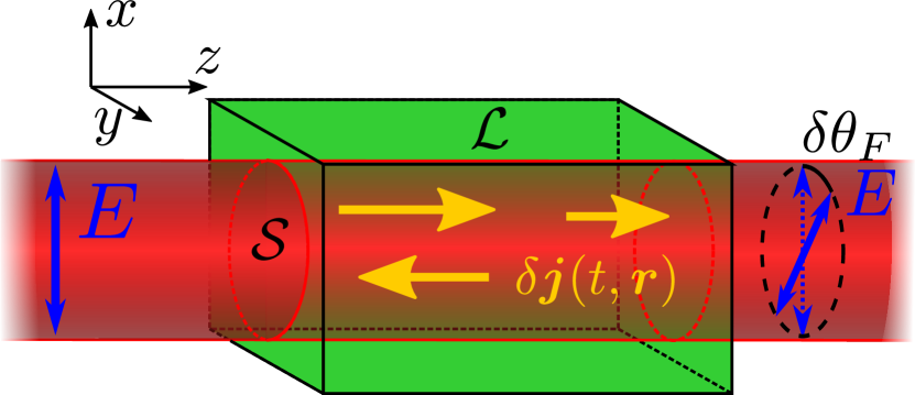
In this paper we point out that omnipresent stochastic fluctuations of electric current, , resulting, e.g., from the Brownian motion of electrons in the thermal equilibrium give rise to the stochastic rotation of the light polarization plane as it passes through a gyrotropic system. Previously, the fluctuations of the Faraday or Kerr rotation of the light polarization plane transmitted through or reflected from the medium have been related with the spin fluctuations in the system Aleksandrov and Zapasskii (1981). This has led to the development of the spin noise spectroscopy technique widely used nowadays to study the spin dynamics of atoms, electrons and nuclei Crooker et al. (2004); Hübner et al. (2014); Zapasskii (2013); Berski et al. (2015). Here we demonstrate that, in addition to the spin noise, in gyrotropic systems, the spectrum of the Faraday and Kerr rotation fluctuations contains information about the electric current fluctuations.
In Sec. II we provide the phenomenological description of the effect based on the symmetry arguments and fluctuation-dissipation theorem. Further, in Sec. III we develop the microscopic theory of the effect for the most prominent gyrotropic semiconductor systems: bulk Te, chiral carbon nanotubes, and quantum wells grown from the zincblende lattice semiconductors such as GaAs. The results are discussed in Sec. IV and summarized in Sec. V.
II Phenomenological description
Let us consider a gyrotropic medium described by the dielectric permittivity tensor with the Cartesian components , hereafter greek subscripts run through . Such a description is applicable to bulk semiconductors, multiple quantum well structures and ensembles of nanotubes Ivchenko (2005). We assume that there are free charge carriers in the system. The optical activity induced by the macroscopic current with the density is described by the phenomenological relation , where is the third rank tensor asymmetric with respect to the permutation of the first two subscripts Ivchenko and Pikus (1978); Vorob’ev et al. (1979). Hereafter the summation over the repeated Greek subscripts, i.e., over the , is assumed. Due to the Brownian motion of the charge carriers the electric current fluctuates in time and space giving rise to stochastic time and coordinate dependent fluctuations of the current density . These current fluctuations, in turn, give rise to the fluctuations of the off diagonal components of the dielectric tensor
| (1) |
Therefore, the current fluctuations lead to fluctuating circular birefringence and dichroism. The fluctuations can thus can be probed by measuring the noise of the Faraday rotation angle of the polarization plane for a linearly polarized light propagating through a sample with the wavevector for specificity or of the Kerr rotation angle of the polarization plane of light reflected from the sample. To be specific, we consider below the case of the Faraday effect and where the rotation angle fluctuation can be recast as
| (2) |
Here is the frequency of light, is the speed of light, is the background refraction index, and is the area of illuminated spot in the sample, Fig. 1. The anisotropy of the background dielectric constants is disregarded. Equation (2) is similar to the well known expression relating regular or stochastic Faraday rotation angle with the magnetization in the illuminated volume Landau and Lifshitz (2004); Aronov and Ivchenko (1973); Giri et al. (2012). It can be rigorously derived assuming that the incident field is linearly polarized, e.g., along the -axis and expressing the induced -component of the electric field via the electrodynamical Greens function, , as . This expression is valid provided that the timescale of the dielectric tensor variations (which is the time scale of the current fluctuations) is much longer as compared with the period of the electromagnetic field oscillations and the time of light passage through the sample. The measured Faraday rotation signal can be recast in the form Glazov (2012), where the integration is carried out over the detector surface area, . These expressions together with the asymptotic form of the Greens function, , yield Eq. (2). Note, that the Faraday rotation caused by the natural optical activity of the medium, , is static and, therefore, does not contribute in the noise of the rotation signal (2) detected in experiments.
In the Faraday rotation noise experiments the Fourier transform of the Faraday rotation autocorrelation function,
| (3) |
is measured Here and in what follows we consider only equilibrium fluctuations, hence, the averaging over in the definition of the autocorrelation function, Eq. (3), is assumed. Making use of Eq. (2) we finally obtain
| (4) |
where is the length of the sample, is the Fourier transform of the correlation function of homogeneous in the space () fluctuations of electric current density components in the illuminated volume of the sample, . For completeness we present here the definition of the current density components correlation functions Gantsevich et al. (1979)
| (5) |
with the angular brackets denoting averaging over and . In what follows the superscript is omitted.
In the thermal equilibrium the correlator in Eq. (4) is proportional to the ac conductivity of the system, ,
| (6) |
where is the temperature and is the Boltzmann constant Kubo (1966); Gantsevich et al. (1979). In the nonequilibrium steady state conditions the correlators of current fluctuations do not, in general, reduce to any response function, and can be calculated following the formalism proposed in Ref. Gantsevich et al., 1979.
Equations (4) and (6) can be combined as
| (7) |
which clearly demonstrates that the electric current fluctuations described by the conductivity of the system manifest themselves in the noise of the Faraday rotation. Particularly for the conductivity described by the Drude formula Note2 ; Gantsevich et al. (1979); platzman1973solid .
| (8) |
where is the concentration of free charge carriers, is the charge carrier effective mass, is its momentum relaxation time, and is the Kronecker symbol, one can readily obtain the expression for the mean square fluctuation of Faraday rotation angle
| (9) |
The magnitude of the single time mean square fluctuation of the Faraday rotation angle is, in agreement with physical arguments, linearly proportional to the charge carrier density and the temperature and is inversely proportional to the effective mass. We note that the measured signal scales as , which paves the way towards increasing of the sensitivity by increasing the sample length and making the focussing of the probe beam tighter just like in the conventional spin noise spectroscopy Hübner et al. (2014); Glazov and Zapasskii (2015).
In the following section we provide the microscopic theory for for a number of gyrotropic semiconductor systems and give the estimations of the root mean square Faraday rotation in these systems.
III Microscopic models
Below we consider four prominent gyrotropic systems, namely, bulk tellurium, macroscopic ensemble of chiral carbon nanotubes, and quantum well structures based on GaAs (or similar) semiconductor grown along and axes.
III.1 Bulk tellurium
The bulk Te has symmetry being a prototypical gyrotropic crystal Ivchenko and Pikus (1975); Dubinskaya and Farbshtein (1978), whose electrooptical properties attract continued interest Agapito et al. (2013); Shalygin et al. (2016). It has two modifications: right and left handed, in which the atoms are placed along the spirals with different chiralities Tanaka et al. (2010). The axes of the spirals form the hexagonal lattice, as sketched in Fig. 2(a) for the example of right handed modification. The extrema of the conduction and valence bands are located near and points of the Brillouin zone [see inset in Fig. 2(b)], and the band structure in the vicinity of these extrema points is illustrated in Fig. 2(b). The conduction band is twofold spin degenerate at and points. The dispersion for electrons with spin projection on the threefold rotation axis , , is given by Ivchenko and Pikus (1978)
| (10) |
Here and are the components of the electron wavevector along the axis and in the plane perpendicular to it (reckoned from the or point), is the bandgap energy and describes the spin-orbit splitting in the conduction band. The degeneracy of the valence band is completely lifted and in electron representation the dispersion of the topmost valence subband reads
| (11) |
where with and being the material parameters. The quantity determines the splitting between the valence subbands. The parameters and change the signs at the transformation between the right and left handed modifications of Te. The wavefunction in the valence band is combined from the states with spin projections as
| (12) |
Equation (12) shows that the valence band electron spin orientation is locked with the its wavevector, hence, the electric current in the valence band is directly related to the hole spin polarization. Equations (10)—(12) have the same form in and valleys of the energy spectrum. In this particular material the hole spin and current fluctuations can not be separated.
(a)
\includemovie[poster,
toolbar,
label=pt,
text=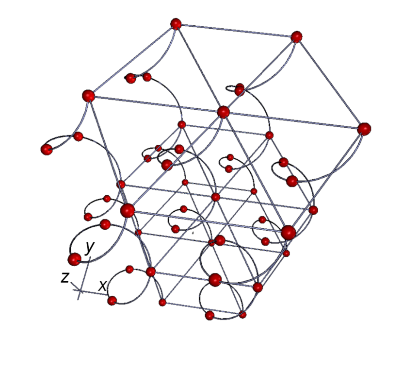 ,
3Droo=1.7532683988025128,
3Daac=60.000001669652114,
3Dcoo=0.05479823797941208 0.000023365430024568923 0.5929998755455017,
3Dc2c=0.05754242092370987 -0.45956751704216003 0.8862767815589905,
3Droll=-1.2335996122223567,
3Dlights=CAD,
3Drender=SolidOutline]
helixXYZ.u3d
,
3Droo=1.7532683988025128,
3Daac=60.000001669652114,
3Dcoo=0.05479823797941208 0.000023365430024568923 0.5929998755455017,
3Dc2c=0.05754242092370987 -0.45956751704216003 0.8862767815589905,
3Droll=-1.2335996122223567,
3Dlights=CAD,
3Drender=SolidOutline]
helixXYZ.u3d
(b)
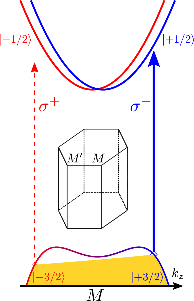
We consider the experimentally relevant case of the -doped Te Shalygin et al. (2016) and assume that the light propagates along the threefold rotation axis .To demonstrate the effect, we consider the interband transitions between the topmost valence subband and the conduction band, as illustrated in Fig. 2(b). At the microscopic level the contributions to dielectric tensor components from these transitions can be expressed as Agranovich and Ginzburg (1984)
| (13) |
where [] is the distribution function of holes in the topmost valence subband in the valley [], are the dipole moment matrix elements in circular polarizations, and we have neglected the spin-orbit splitting of the conduction band because . Hereafter is used as the normalization volume. We note that the states in and valleys are related by the time reversal symmetry only and the current induced contributions to from the two valleys have the same absolute value and sign. The quantity , Eq. (1), describing the stochastic current induced Faraday rotation in Eqs. (4), (9) thus reads
| (14) |
Here is the electron charge, is the interband momentum matrix element (which can be related with and within the two band model Averkiev et al. (1984)). Hereafter we assume that the probe energy is below the absorption threshold, , so that the probe beam propagates within the transparency frequency range. In derivation of Eq. (14) we have considered only linear in contributions. Equation (14) is valid for small detunings, and for not too high hole density, such that the hole Fermi energy . It is in agreement with Ref. Vorob’ev et al. (1979) where the Faraday rotation caused by the homogeneous dc current in Te was studied.
It is instructive to introduce the parameter Shalygin et al. (2012)
| (15) |
with being the refraction index in the plane perpendicular to the main crystal axis. It follows from Eq. (2) that is an analog of the Verdet constant for the current induced Faraday rotation, and can be measured experimentally. The mean square of the fluctuations of current induced Faraday rotation can be found using Eq. (9). For the estimation we take the values close to the parameters used in Ref. Shalygin et al., 2012, namely, m/A, mm, cm-3, K, with mm, and with being the free electron mass. For this set of parameters we obtain .
III.2 Chiral carbon nanotubes
Another interesting gyrotropic system is an ensemble of chiral carbon nanotubes Iijima (1991). The single walled carbon nanotube can be conveniently characterized by the circumferential vector mapping the two dimensional graphene sheet to the cylinder circumference Ivchenko (2005); Saito et al. (1998), , where , are the integers and , are the basic vectors of the graphene lattice. There are two series of conduction and valence subbands in carbon nanotubes stemming from the states in the two valleys and of graphene. The dispersion relations for these subbands read
| (16) |
where the integer enumerates the subbands, () is the wavenumber of the translational motion along the nanotube axis reckoned from the corresponding Brillouin zone edge, the remaining parameters such as the energy gaps (), effective masses () and the constants () can be expressed through the parameters of the graphene sheet, i.e. transfer integral and the lattice constant, and the angle between the vectors and Ivchenko (2005). Top and bottom signs in Eq. (16) correspond to the conduction and valence bands, respectively. The time reversal symmetry ensures that in Eq. (16). The nanotube chirality results in the coupling between the translational motion along the nanotube axis and the electron angular momentum making the electron spectrum asymmetric in the -space, see Fig. 3(a) and Ref. Ivchenko and Spivak (2002) for details.
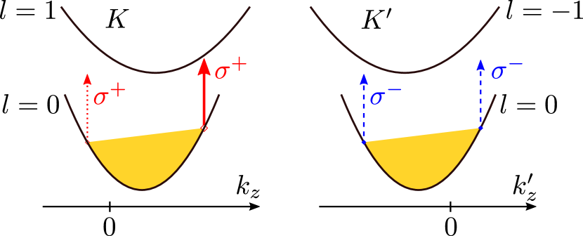
In order to simplify the derivation of the off diagonal components of the dielectric tensor responsible for the Faraday rotation we assume that the nanotubes form a three dimensional ensemble; the tubes in the ensemble are identical, have the same chirality , and are oriented along axis. The nanotube chirality is most prominent for intersubband transitions for light propagating along the nanotube axis. These transitions are accompanied by the change of the subband state by depending on the incident light helicity (the interband transitions are considered in detail in Ref. Goupalov (2005)). Hence, we focus on the energy range of to intersubband transitions. We assume that the length of each nanotube is by far smaller than the wavelength of the incident light, therefore, we use the effective medium approximation and present the dielectric tensor components analogously to Eq. (13)
| (17) |
Here the extra factor as compared with Eq. (13) results from the summation over the spin states, enumerates the nanotubes in the ensemble, [] is the electron distribution function in the ground conduction subband of the valley [], and the occupation of excited subbands is neglected. The squared absolute value of the dipole moment operator for the intersubband transition reads , where is a parameter Ivchenko and Spivak (2002).
Equation (17) shows that there are two contributions to the off diagonal components of the dielectric tensor. First, the imbalance of the occupancies in and valleys results in the preference of the transitions in or polarizations yielding the valley polarization induced Faraday rotation:
| (18) |
Here is the valley population imbalance in the nanotube ensemble and
| (19) |
where and with being the Fermi wavevector and being the Fermi energy. Equation (19) is derived for the degenerate electrons, , with not too high density where , and we have taken into account that and . Corresponding Faraday rotation noise power spectrum reads
| (20) |
where is the power spectrum of the valley population imbalance in the nanotube ensemble Note (3). Second, the asymmetry of the conduction subbands energy spectrum gives rise to the current induced Faraday rotation with
| (21) |
where we have used the relation .
In order to estimate the same time mean square of the Faraday rotation angle we make use of the relations
| (22a) | |||
| (22b) | |||
where is the equilibrium distribution function, is the concentration of electrons in the ensemble. These equations express the single time fluctuations of the current and of the valley population imbalance.
Interestingly, the valley polarization fluctuations induced Faraday rotation noise, Eqs. (19), (20), and the current fluctuations induced Faraday rotation noise, Eqs. (21), (4), demonstrate quite different dependence on the detuning and, hence, on the probe frequency . This is because is inversely proportional to the detuning, , while is inversely proportional to . The different dependence of for two mechanisms on the detuning allows one, in principle, to separate these two contributions in the experiments similar to those described in Ref. Zapasskii et al. (2013).
Another way to separate the contributions due to current and valley polarization noise is their different power spectra as functions of the noise frequency . The different dependence on is due to the fact that the timescale of valley fluctuations, that is the intervalley scattering time , is, as a rule, strongly different from that of the current fluctuations controlled by shorter momentum relaxation time or the time of flight for ballistic nanotubes. Moreover, weak electrical connections between the nanotubes in the ensemble may result in the specific frequency dependence of , particularly with a power law feature at Zvyagin .
For the estimations we take meV, nm, meVnm, K, , two dimensional concentration of nanotubes cm-2 and make use of the standard expressions introduced in Ref. Ivchenko and Spivak (2002) to derive and . At the detuning meV the mean square fluctuation caused by valley polarization fluctuations amounts to mrad and by current fluctuations to mrad. These contributions are of the same order at smaller detuning meV, but in this case the fluctuations of higher powers of the current density or the correlations between the valley polarization and the current, if any, may play a role.
Above we considered an ensemble of identical nanotubes. We note that in ensemble of nanotubes with different chiralities and equal numbers of and nanotubes, the gyrotropy is absent on average, but the current and valley polarization fluctuations induced stochastic Faraday rotation is still present.
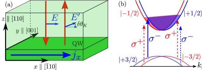
III.3 Zincblende lattice quantum wells grown along the axis
Although bulk zincblende lattice semiconductors like GaAs are not gyrotropic, the QW structures grown from these materials demonstrate gyrotropy 2016arXiv160701226K . In particular, quantum wells grown along direction with symmetric heteropotential have the point symmetry group. In the coordinate frame with the in plane axes , the twofold rotation axis lies in the intersection of reflection planes and , Fig. 4(a). Hence, the in plane -component of a vector, i.e., current density , transform like -component of a pseudovector. As a result, in the plane current fluctuations give rise to the noise of the Faraday or Kerr rotation for the probe beam incident along the structure normal . The origin of this effect is the spin orbit interaction, which allows for the terms in the effective Hamiltonian (see Refs. Dyakonov and Kachorovskii (1986); Nestoklon et al. (2012) and references therein)
| (23) |
where () is the spin splitting parameters for the electron (hole), () is the spin (pseudospin) -component Pauli matrix acting in the basis of electron ( heavy-hole) spin states, () is the -component of the electron (hole) wavevector. In what follows, we consider the reflection geometry, as sketched in Fig. 4(a), and calculate the Kerr rotation noise caused by the electric current fluctuations.
Optical response of two dimensional structures can be conveniently characterized by the matrix of reflection coefficients, , which links the Cartesian components of the electric field in the incident and reflected waves. By analogy with Eqs. (13) and (17) for the dielectric tensor, the off diagonal components of the reflection coefficients matrix read Averkiev and Glazov (2007); Glazov (2012)
| (24) |
Here we consider -doped quantum well and focus on the spectral range of interband transitions [see Fig. 4(b)], are the distribution functions of the electrons with spin component , is the band gap including the size quantization energies, , is the reduced mass of electron and hole, is taken to be the normalization area, and is the dipole moment matrix element between the size quantized conduction and valence band electron states. The latter is given by Ivchenko (2005)
| (25) |
where is the dipole moment matrix element between conduction and valence band Bloch amplitudes at the point, and are the envelope functions at in the conduction and valence bands, respectively. The Kerr rotation angle of the reflected light polarization plane can be expressed as Zhukov et al. (2007); Smirnov et al. (2015)
| (26) |
where is the background reflection coefficient, which is usually determined by the cap layer, for simplicity it is assumed to be real. Here, as before, we neglect the regular optical anisotropy of the structure.The off diagonal transmission coefficients have the same form as , in Eq. (24).
Similarly to the chiral carbon nanotubes considered in Sec. III.2 where the stochastic Faraday rotation is contributed both by current and valley noise, in semiconductor quantum wells, in addition to the current induced contribution, which is in the main focus of our paper, the spin polarization also contributes to the Faraday and Kerr effects. The spin polarization effect has been already studied in detail theoretically and experimentally, see, e.g., Refs. Glazov (2012); Poltavtsev et al. (2014) and references therein. Correspondingly,
| (27) |
where is the spin density and
| (28) |
| (29) |
with being the electron effective mass, and, as above, we neglected the shift of the absorption edge caused by the state filling effect as well as the many body effects Averkiev and Glazov (2007). In two dimensional system instead of Eq. (7) we have
| (30) |
where is the two dimensional ac conductivity given by the Drude formula Eq. (8) with being the two dimensional electron density. The root mean square of the current noise induced Kerr rotation noise amounts to for the parameters eV, interband matrix element eV, , meVnm Luo et al. (2010); Durnev et al. (2014), , meV, cm-2, m2, K. At the same conditions, the root mean square of the spin noise induced Kerr angle is just somewhat larger, Note (4).
Note, that in multiple quantum well structures with sufficiently thick barriers where both the electron tunnelling between the wells and the Coulomb interwell interaction are suppressed, the current induced noise power increases linearly with the number of quantum wells in the structure.
III.4 Zincblende lattice quantum wells grown along the axis
For the normal light incidence the current induced Faraday and Kerr effects are symmetry forbidden in zincblende quantum wells grown along the cubic axis, . However, these quantum wells are gyrotropic as well, see Ref. 2016arXiv160701226K and references therein. Here the current induced rotation of the polarization plane is possible at the oblique incidence only. To illustrate this phenomena we consider the case of a grown quantum well with the dominant structural inversion asymmetry.
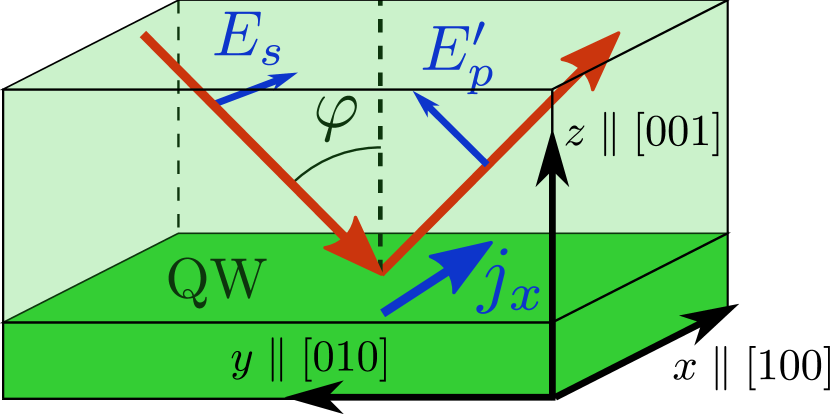
Let us consider the -polarized light incident upon the quantum well, let be the incidence plane and be the angle of incidence inside the structure, Fig. 5(b), the in plane axes are , . The Kerr rotation is described by the off diagonal reflection coefficients Note (5). Taking into account the heavy-light hole mixing via the off diagonal element of the Luttinger Hamiltonian Ivchenko (2005) in the first order we present the electron wavefunction in the valence band with the in plane wave vector in the form Merkulov et al. (1991)
| (31) |
where is the quantum well width, is the in plane position vector, are the Bloch amplitudes of the valence band, and are the envelope functions describing size quantization. Note that in quantum wells with asymmetric heteropotential these functions does not possess a certain parity with respect to reflection. Making use of the selection rules for the interband optical transitions we obtain
| (32) |
where
| (33a) | |||
| (33b) | |||
and the other notations are the same as in previous subsection. The fact that simultaneously both and are nonzero is related with the structural inversion asymmetry of the considered quantum well.
One can see from Eq. (32), that apart from the well studied spin induced Faraday rotation, described by the last term in the square brackets in Eq. (32), at oblique incidence there are two additional contributions to the polarization conversion effect
| (34) |
with being the spin current density along axis. The fact that the spin current contributes to polarization conversion is expected, because induces as a result of the spin-Hall effect Dyakonov (2008); Note (6). The calculation yields
| (35) |
which is derived under the same assumptions as Eq. (29). The Kerr rotation angle reads , where is the reflection coefficient for polarized light. Note that accounting for the phase associated with the light propogation through the cap layer the becomes complex, which allows for optical detection of spin current fluctuations. The power spectrum of the Kerr rotation noise related to electric current fluctuations is given by Eq. (30) with the replacement of by . The estimates show that at Å, the incidence angle , and other parameters as in Sec. III.3.
IV Discussion
In gyrotropic systems the and polarized light differently interacts with the electrons with the given momentum. The fluctuations of the current in the sample lead to the redistribution of the electrons in the momentum space, and therefore result in fluctuations of the light refraction indices for the two circular polarizations, . Hence, the stochastic Faraday or Kerr rotation is induced in gyrotropic systems due to the electric current noise.
Just like in any system, the electron spin fluctuations manifest themselves as an additive to Eq. (2) contribution to the Faraday rotation angle, . Here the third rank pseudotensor describes spin induced optical activity, Landau and Lifshitz (2004); Aronov and Ivchenko (1973); Giri et al. (2012). As a result, the current noise in the Faraday rotation fluctuation spectrum, Eq. (4), is superimposed on the spin noise spectrum. As a rule, the typical timescales of spin dynamics (spin relaxation time , spin precession period in the external magnetic field ) are much longer as compared with the timescales of the orbital dynamics of the electrons given by the momentum relaxation time or the cyclotron period due to relative weakness of the spin orbit coupling in many semiconductor systems. Hence, the spin and current fluctuations can be readily separated in the experiment Note (7). Moreover, the gyrotropy of the considered systems allows for linear relations between the spin and current (spin galvanic and spin orientation by the electric field effects), this makes spin and current fluctuations interrelated. The analysis of such cross correlation noise and its manifestations is beyond the scope of the present paper. For the same reasons we do not address the cross correlations between, e.g., the electric current and valley polarization fluctuations in carbon nanotubes.
The manifestation of the current noise in the Faraday or Kerr rotation fluctuations allows, in principle, for the contactless measurement of the conductivity of the system. It may serve as an alternative to the studies of the transport response function in the light scattering experiments platzman1973solid ; Gantsevich et al. (1979); Bareikis et al. (1992). The link between the two approaches is similar to the relation between the spin noise spectroscopy and the spin-flip Raman scattering spectroscopy, see Refs. Gorbovitskii and Perel (1983); Glazov and Zapasskii (2015) for details.
V Conclusion
To conclude, we have demonstrated that in gyrotropic systems the electric current fluctuations result in the stochastic rotation of the polarization plane of the linearly polarized light propagating through the system. Just like spin fluctuations, the current noise results in the noise of the Faraday or Kerr rotation effects. Hence, in gyrotropic materials one can access the electric current correlation function, and, particularly, the ac conductivity by means of optical noise spectroscopy. The microscopic theory of the effect has been developed for bulk tellurium, ensembles of carbon nanotubes, and two-dimensional systems, such as GaAs quantum wells grown along different crystallographic directions. The estimates show that among the studied systems the effect is strongest in quantum well structures.
Acknowledgements.
We thank E. L. Ivchenko for fruitful discussions and S. G. Smirnov for technical support. Partial support from RFBR (projects 15-02-06344 and 15-32-20828), the Dynasty Foundation and RF President Grant No. SP-643.2015.5 is gratefully acknowledged.References
- Sturman and Fridkin (1992) B. I. Sturman and V. M. Fridkin, The photovoltaic and photorefractive effects in non-centrosymmetric materials (Gordon and Breach, New York, 1992).
- (2) E. L. Ivchenko and G. E. Pikus, in Semiconductor Physics, edited by V. M. Tuchkevich and V. Ya. Frenkel (Cons. Bureau, New York, 1986).
- Ivchenko and Pikus (1978) E. L. Ivchenko and G. E. Pikus, ‘‘New photogalvanic effect in gyrotropic crystals,’’ JETP Lett. 27, 604 (1978).
- Aronov and Lyanda-Geller (1989) A. G. Aronov and Yu. B. Lyanda-Geller, ‘‘Nuclear electric resonance and orientation of carrier spins by an electric field,’’ JETP Lett. 50, 431 (1989).
- Edelstein (1990) V. M. Edelstein, ‘‘Spin polarization of conduction electrons induced by electric current in two-dimensional asymmetric electron systems,’’ Solid State Commun. 73, 233 (1990).
- Kato et al. (2004) Y. K. Kato, R. C. Myers, A. C. Gossard, and D. D. Awschalom, ‘‘Current-induced spin polarization in strained semiconductors,’’ Phys. Rev. Lett. 93, 176601 (2004).
- Silov et al. (2004) A. Yu. Silov, P. A. Blajnov, J. H. Wolter, R. Hey, K. H. Ploog, and N. S. Averkiev, ‘‘Current-induced spin polarization at a single heterojunction,’’ Appl. Phys. Lett. 85, 5929 (2004).
- Ganichev et al. (2006) S. D. Ganichev, S. N. Danilov, Petra Schneider, V. V. Bel’kov, L. E. Golub, W. Wegscheider, D. Weiss, and W. Prettl, ‘‘Electric current-induced spin orientation in quantum well structures,’’ J. Magn. Magn. Mater. 300, 127 (2006).
- Ivchenko et al. (1989) E. L. Ivchenko, Yu. B. Lianda-Geller, and G. E. Pikus, ‘‘Photocurrent in quantum well structures with optical orientation of free carriers,’’ JETP Lett. 50, 175 (1989).
- Ganichev et al. (2002) S. D. Ganichev, E. L. Ivchenko, V. V. Bel’kov, S. A. Tarasenko, M. Sollinger, D. Weiss, W. Wegscheider, and W. Prettl, ‘‘Spin-galvanic effect,’’ Nature 417, 153 (2002).
- (11) E. I. Rashba and V. I. Sheka, ‘‘Symmetry of energy bands in crystals of wurtzite type: II. Symmetry of bands including spin-orbit interaction,’’ Sov. Phys. Solid State: Collected Papers 2, 162 (1959). E. I. Rashba, ‘‘Properties of semiconductors with an extremum loop. I. Cyclotron and comninational resonance in a magnetic field perpendicular to the plane of the loop,’’ Sov. Phys. Solid State 2, 1109 (1960).
- Ganichev and Golub (2014) S. D. Ganichev and L. E. Golub, ‘‘Interplay of Rashba/Dresselhaus spin splittings probed by photogalvanic spectroscopy — a review,’’ Physica Status Solidi B 251, 1801 (2014).
- Landau and Lifshitz (2004) L. D. Landau and E. M. Lifshitz, Electrodynamics of Continuous Media (vol. 8) (Butterworth-Heinemann, Oxford, 2004).
- Baranova et al. (1977) N. B. Baranova, Yu. V. Bogdanov, and B. Ya. Zel’dovich, ‘‘Electrical analog of the Faraday effect and other new optical effects in liquids,’’ Opt. Commun. 22, 243 (1977).
- Vorob’ev et al. (1979) L. E. Vorob’ev, E. L. Ivchenko, G. E. Pikus, I. I. Farbshtein, V. A. Shalygin, and A. V. Shturbin, ‘‘Optical activity in tellurium induced by a current,’’ JETP Lett. 29, 441 (1979).
- Aleksandrov and Zapasskii (1981) E. B. Aleksandrov and V. S. Zapasskii, ‘‘Magnetic resonance in the Faraday-rotation noise spectrum,’’ JETP 54, 64 (1981).
- Crooker et al. (2004) S. A. Crooker, D. G. Rickel, A. V. Balatsky, and D. L. Smith, ‘‘Spectroscopy of spontaneous spin noise as a probe of spin dynamics and magnetic resonance,’’ Nature 431, 49 (2004).
- Hübner et al. (2014) J. Hübner, F. Berski, R. Dahbashi, and M. Oestreich, ‘‘The rise of spin noise spectroscopy in semiconductors: From acoustic to GHz frequencies,’’ Physica Status Solidi B 251, 1824 (2014).
- Zapasskii (2013) V. S. Zapasskii, ‘‘Spin-noise spectroscopy: from proof of principle to applications,’’ Adv. Opt. Photon. 5, 131 (2013).
- Berski et al. (2015) F. Berski, J. Hübner, M. Oestreich, A. Ludwig, A. D. Wieck, and M. M. Glazov, ‘‘Interplay of electron and nuclear spin noise in -type gaas,’’ Phys. Rev. Lett. 115, 176601 (2015).
- Ivchenko (2005) E. L. Ivchenko, Optical spectroscopy of semiconductor nanostructures (Alpha Science, Harrow UK, 2005).
- Aronov and Ivchenko (1973) A. G. Aronov and E. L. Ivchenko, ‘‘Dichroism and optical anisotropy of media with oriented spins of free electrons,’’ Sov. Phys. Solid State 15, 160 (1973).
- Giri et al. (2012) R. Giri, S. Cronenberger, M. Vladimirova, D. Scalbert, K. V. Kavokin, M. M. Glazov, M. Nawrocki, A. Lemaitre, and J. Bloch, ‘‘Giant photoinduced Faraday rotation due to the spin-polarized electron gas in an -GaAs microcavity,’’ Phys. Rev. B 85, 195313 (2012).
- Glazov (2012) M. M. Glazov, ‘‘Coherent spin dynamics of electrons and excitons in nanostructures (a review),’’ Phys. Solid State 54, 1 (2012).
- Gantsevich et al. (1979) S. Gantsevich, V. Gurevich, and R. Katilius, ‘‘Theory of fluctuations in nonequilibrium electron gas,’’ La Rivista del Nuovo Cimento 2, 1 (1979).
- Kubo (1966) R. Kubo, ‘‘The fluctuation-dissipation theorem,’’ Rep. Prog. Phys. 29, 255 (1966).
- (27) The analysis of applicability (i) of Eq. (8\@@italiccorr), (ii) of the current propagation in the sample, (iii) relation of the current noise to the electron density noise is beyond the scope of the present work Gantsevich et al. (1979); platzman1973solid .
- (28) P. M. Platzman and P. A. Wolff, Waves and Interactions in Solid State Plasmas, Vol. 13 (Academic, New York, 1973).
- Glazov and Zapasskii (2015) M. M. Glazov and V. S. Zapasskii, ‘‘Linear optics, raman scattering, and spin noise spectroscopy,’’ Opt. Express 23, 11713 (2015).
- Ivchenko and Pikus (1975) E. L. Ivchenko and G. E. Pikus, ‘‘Natural optical activity of semiconductors (Te),’’ Sov. Phys. Solid State 16, 1261 (1975).
- Dubinskaya and Farbshtein (1978) L. S. Dubinskaya and I. I. Farbshtein, ‘‘Natural optical activity and features of the structure of the electronic energy spectrum of tellurium,’’ Sov. Phys. Solid State, 20, 437 (1978).
- Agapito et al. (2013) L. A. Agapito, N. Kioussis, W. A. Goddard, and N. P. Ong, ‘‘Novel family of chiral-based topological insulators: elemental tellurium under strain,’’ Phys. Rev. Lett. 110, 176401 (2013).
- Shalygin et al. (2016) V. A. Shalygin, M. D. Moldavskaya, S. N. Danilov, I. I. Farbshtein, and L. E. Golub, ‘‘Circular photon drag effect in bulk tellurium,’’ Phys. Rev. B 93, 045207 (2016).
- Tanaka et al. (2010) Y. Tanaka, S. P. Collins, S. W. Lovesey, M. Matsumami, T. Moriwaki, and S. Shin, ‘‘Determination of the absolute chirality of tellurium using resonant diffraction with circularly polarized x-rays,’’ J. Phys.: Condens. Matter 22, 122201 (2010).
- Agranovich and Ginzburg (1984) V. M. Agranovich and V. L. Ginzburg, Crystal optics with spatial dispersion, and excitons (Springer-Verlag (Berlin and New York), 1984).
- Averkiev et al. (1984) N. S. Averkiev, V. M. Asnin, A. A. Bakun, A. M. Danishevskii, E. L. Ivchenko, G. E. Pikus, and A. A. Rogachev, ‘‘Circular photogalvanic effect in tellurium. 1. Theory,’’ Sov. Phys. Semicond. 18, 397 (1984).
- Shalygin et al. (2012) V. A. Shalygin, A. N. Sofronov, L. E. Vorob’ev, and I. I. Farbshtein, ‘‘Current-induced spin polarization of holes in tellurium,’’ Phys. Solid State 54, 2362 (2012).
- Iijima (1991) S. Iijima, ‘‘Helical microtubules of graphitic carbon,’’ Nature 354, 56 (1991).
- Saito et al. (1998) R. Saito, G. Dresselhaus, and M. S. Dresselhaus, Physical Properties of Carbon Nanotubes (Imperial College Press, 1998).
- Ivchenko and Spivak (2002) E. L. Ivchenko and B. Spivak, ‘‘Chirality effects in carbon nanotubes,’’ Phys. Rev. B 66, 155404 (2002).
- Goupalov (2005) S. V. Goupalov, ‘‘Optical transitions in carbon nanotubes,’’ Phys. Rev. B 72, 195403 (2005).
- Note (3) Note that the similar effect for the transition metal dichalcogenides monolayers was studied theoretically in Ref. Tse et al. (2014). In these materials, however, the current induced Faraday rotation fluctuations are forbidden due to the point symmetry.
- Zapasskii et al. (2013) V. S. Zapasskii, A. Greilich, S. A. Crooker, Yan Li, G. G. Kozlov, D. R. Yakovlev, D. Reuter, A. D. Wieck, and M. Bayer, ‘‘Optical spectroscopy of spin noise,’’ Phys. Rev. Lett. 110, 176601 (2013).
- (44) I. Zvyagin, in Charge Transport in Disordered Solids with Applications in Electronics, edited by Sergei Baranovski (John Wiley and Sons, Ltd., Chichester, UK, 2006).
- (45) L. V. Kotova, A. V. Platonov, V. N. Kats, V. P. Kochereshko, S. V. Sorokin, S. V. Ivanov, and L. E. Golub, ‘‘Optical activity of quantum wells,’’ Phys. Rev. B 94, 165309 (2016).
- Dyakonov and Kachorovskii (1986) M. I. Dyakonov and V. Yu. Kachorovskii, ‘‘Spin relaxation of two-dimensional electrons in noncentrosymmetric semiconductors,’’ Sov. Phys. Semicond. 20, 110 (1986).
- Nestoklon et al. (2012) M. O. Nestoklon, S. A. Tarasenko, J.-M. Jancu, and P. Voisin, ‘‘Spin splitting of electron states in (110) quantum wells: Symmetry analysis and kp theory versus microscopic calculations,’’ Phys. Rev. B 85, 205307 (2012).
- Averkiev and Glazov (2007) N. S. Averkiev and M. M. Glazov, ‘‘Light-matter interaction in doped microcavities,’’ Phys. Rev. B 76, 045320 (2007).
- Zhukov et al. (2007) E. A. Zhukov, D. R. Yakovlev, M. Bayer, M. M. Glazov, E. L. Ivchenko, G. Karczewski, T. Wojtowicz, and J. Kossut, ‘‘Spin coherence of a two-dimensional electron gas induced by resonant excitation of trions and excitons in CdTe/(Cd,Mg)Te quantum wells,’’ Phys. Rev. B 76, 205310 (2007).
- Smirnov et al. (2015) D. S. Smirnov, M. M. Glazov, E. L. Ivchenko, and L. Lanco, ‘‘Theory of optical spin control in quantum dot microcavities,’’ Phys. Rev. B 92, 115305 (2015).
- Poltavtsev et al. (2014) S. V. Poltavtsev, I. I. Ryzhov, M. M. Glazov, G. G. Kozlov, V. S. Zapasskii, A. V. Kavokin, P. G. Lagoudakis, D. S. Smirnov, and E. L. Ivchenko, ‘‘Spin noise spectroscopy of a single quantum well microcavity,’’ Phys. Rev. B 89, 081304 (2014).
- Luo et al. (2010) J. W. Luo, A. N. Chantis, M. van Schilfgaarde, G. Bester, and A. Zunger, ‘‘Discovery of a novel linear-in- spin splitting for holes in the 2D system,’’ Phys. Rev. Lett. 104, 066405 (2010).
- Durnev et al. (2014) M. V. Durnev, M. M. Glazov, and E. L. Ivchenko, ‘‘Spin-orbit splitting of valence subbands in semiconductor nanostructures,’’ Phys. Rev. B 89, 075430 (2014).
- Note (4) Our estimations can not be directly compared with Ref. \rev@citealpGanichev2006127, because experimentally the Faraday rotation was detected by terahertz radiation in this work.
- Note (5) In the case of the dominant bulk inversion asymmetry .
- Merkulov et al. (1991) I. A. Merkulov, V. I. Perel’, and M. E. Portnoi, ‘‘Momentum alignment and spin orientation of photoexcited electrons in quantum wells,’’ JETP 72, 669 (1991).
- Dyakonov (2008) M. I. Dyakonov, ed., Spin physics in semiconductors (Springer-Verlag: Berlin, Heidelberg, 2008).
- Note (6) For the same reason can also contribute to , but this effect appears only in the second order in heavy–light hole mixing.
- Note (7) The general analysis of the strong spin orbit coupling limit is beyond the scope of the present paper. Here we note only that in such a situation the spin and current fluctuations may be indistinguishable, see Sec. III.1 for details.
- Bareikis et al. (1992) V. Bareikis, R. Katilius, J. Pozhela, S. V. Gantsevich, and V. L. Gurevich, ‘‘Fluctuation spectroscopy of hot electrons in semiconductors,’’ in Spectroscopy of Nonequilibrium Electrons and Phonons, Modern Problems in Condensed Matter Sciences, edited by B. P. Zakharchenya and C. V. Shank (Elsevier, Amsterdam, 1992).
- Gorbovitskii and Perel (1983) B. M. Gorbovitskii and V. I. Perel, ‘‘Aleksandrov and Zapasskii experiment and the Raman effect,’’ Opt. Spectrosc. 54, 229 (1983).
- Tse et al. (2014) Wang-Kong Tse, A. Saxena, D. L. Smith, and N. A. Sinitsyn, ‘‘Spin and valley noise in two-dimensional Dirac materials,’’ Phys. Rev. Lett. 113, 046602 (2014).