Out-of-Band Radiation from Large Antenna Arrays
Abstract
Co-existing wireless systems, which share a common spectrum, need to mitigate out-of-band (oob) radiation to avoid excessive interference. For legacy systems, oob radiation is well understood and is commonly handled by digital precompensation techniques. When using large arrays, however, new phenomena and hardware limitations have to be considered. First, signals can be radiated directionally, which might focus the oob radiation. Second, low-complexity hardware is used for cost reasons, which increases the relative amount of oob radiation. Given that massive mimo and millimeter wave communication rely on base stations with a large number of antennas, the spatial behavior of oob radiation from large arrays will have significant implications for the hardware requirements of future base stations. We show that, if the oob radiation is beamformed, its array gain is never larger than that of the in-band signal. In many cases, the oob radiation is close to isotropic even when the in-band signal is highly directive. With the same total radiated power, the oob radiation from large arrays is therefore never more severe than from a legacy system with the same adjacent-channel-leakage ratio. Further, the oob radiation is less detrimental than from a legacy system since the high array gain of the in-band signal allows large arrays to radiate less total power than legacy systems. We also show how oob radiation from large arrays varies with location in static propagation environments and how these effects vanish when averaged over the small-scale fading. Since a higher relative amount of oob radiation can be tolerated for large arrays, the linearity requirement can be relaxed as compared to legacy systems. Specifically, less stringent linearity requirements on each transmitter makes it possible to build large arrays from low-complexity hardware.
1 Background
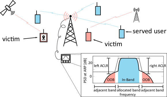
Nonlinear hardware causes a radio system to emit spurious power outside its allocated frequency band. This out-of-band (oob) radiation is illustrated in Figure 1, which shows the power spectral density of a typical transmit signal. The power outside the allocated band could harm the operation of a victim wireless system by interfering with its signal. Therefore, the amount of oob radiation a transmitter is allowed to emit is regulated.
The victim of the oob radiation can be a system with a completely different application and sensitivity from the studied system—e.g., radar stations, telescopes for space research, gnss receivers, radio altimeters. A victim should be distinguished from served users, which are the receivers that operate within the allocated band and to whom the signal is intended. The scenario is depicted in Figure 1, assuming a cellular system.
Commonly, standards require that conducted measurements, i.e. measurements through a physical connection before the antenna at the antenna reference point (arp), of the aclr (Adjacent-Channel Leakage Ratio) be below a certain threshold. The aclr is the ratio between the power in the allocated band and the power in the strongest of the two adjacent bands. The bandwidths of all bands are the same and the allocated band is centered around the carrier frequency and contains the whole desired signal including its excess bandwidth. When there are multiple antennas, each power is measured as the total power summed over all antennas.
The goal of enforcing a constraint is to limit the absolute amount of interference that disturbs a victim. Since aclr only measures this indirectly, an alternative measure is so called over-the-air measurements, where the actual received oob power is measured. This is treated further in Section 6.
2 OOB Radiation from Large Arrays is Different
Large arrays are envisioned to be used in both massive mimo and millimeter wave (mmWave) communication—both key technologies for 5G [1]—to beamform multiple signals to different users. Constructive and destructive interference is used to limit overhearing between users and to increase the received signal power. The extra power the user receives compared to if the signal were sent with the same total power from only one of the antennas is the array gain. It can be used to either lower the radiated power compared to legacy systems or to increase the signal-to-interference-and-noise ratio of the received signal. In many cases, especially in multicell scenarios, the system is interference limited, i.e. while it is possible to lower the transmit power substantially, the signal-to-interference-and-noise ratio can only be improved slightly [2]. The array gain is therefore assumed to be used to lower the transmit power.
The main difference between oob radiation from legacy siso systems and from large arrays is its spatial characteristics, the amount of received power relative to the transmitted power at different points in space. For legacy systems, oob radiation has the same spatial characteristics as the in-band signal. For large arrays however, where the signal envelope and thus the nonlinear distortion is different at each antenna, the spatial characteristics of the oob radiation may differ from that of the in-band signal. If the array gain of the oob radiation is small compared to that of the in-band signal, the low radiated power from large arrays means that a victim receives less oob power than from a legacy system with the same aclr requirement.
Recently, oob radiation from large arrays has been studied in a large number of contributions to 3GPP. Unlike the oob radiation from legacy systems [3, 4], however, oob radiation from large arrays has received little attention in the academic literature. Models for phased arrays for satellite communication have been studied in, e.g., [5], phased arrays with two beams in [6]. Numerical results for large arrays in a frequency-flat system are presented in [7]. In this paper, we use the analytical tools developed in [8] for frequency-selective systems to explain the spatial behavior of oob radiation and to discuss the implications for system design.
The transmission from a large array is studied, e.g. the downlink in a cellular mobile system. It is possible that a victim equipped with a large array could reject oob radiation by performing directive reception. This possibility, however, is left for future research. We illustrate the spatial characteristics of oob radiation for a system that serves multiple users by spatial multiplexing with nonlinear hardware. The nonlinearity used to generate the illustrations is modeled by a third-order polynomial, whose coefficients are fitted to measured data from a class ab amplifier. The setup is agnostic to bandwidth and carrier frequency. We consider signals with Gaussian amplitude distributions and high peak-to-average ratio (par ). This includes most types of transmit signals, such as single-carrier and ofdm signals, because the signals are precoded and are a combination of many independent symbols. There are low-par precoders that produce signals with lower amplitude variations, e.g. [9], to allow for less linear hardware. While there is no reason to believe that the spatial characteristics of the oob radiation from such signals are any different, this remains to be shown in future research.
The properties of the channel change with the carrier frequency. At the high frequencies considered for mmWave communication, the channel has low rank, i.e. there are only one or a few distinct incident paths; whereas at lower frequencies there is more multipath propagation and isotropic scattering. Measurements [10, 11] reveal that, in reality, the channel has both low-rank and isotropic components and the relative significance of the two components changes continuously as frequency changes. To reflect both mmWave and massive mimo communication, we will look at both a low-rank line-of-sight channel and a channel with isotropic scattering. Both static and mobile propagation environments will be considered; see Table 1.
In line-of-sight communication, the time a mobile user equipment spends in one static lobe is relatively long. For example, with 100 antennas separated by half a wavelength, the beamwidth is on the order 1.8∘ and a victim located 100 m from the transmitter and moving at 30 m/s perpendicular to the beam is inside the beam for 100 ms. We therefore model the line-of-sight channel as static, even if there is mobility.
In an environment with isotropic scattering, the victim only has to move half a wavelength to experience a different channel. The static and mobile scenarios therefore have to be studied separately. In some static scenarios, the directivity of the oob radiation must be considered. When either the served users are mobile or the victim is mobile, the amount of received oob radiation will change rapidly. By coherent integration over several coherence times for example, a victim can protect its operation from outage in individual coherence times. Therefore only the average oob radiation is relevant in mobile scenarios.
| static environment | mobile environment | |
|
line-of-sight |
• beampattern is constant for long periods of time, both in static and mobile applications • outage rate/risk matters • beamforming of oob radiation has to be considered | |
|---|---|---|
|
isotropic scattering |
•
coherence times is long compared
to the sensitivity of the victims • outage rate/risk matters • the “beampattern” is static • beamforming of oob radiation has to be considered |
• short coherence time • ergodic rate/performance matters • victims can code over many coherence times • oob radiation beampattern changes rapidly • average oob radiation has to be considered |
3 Line-of-Sight Channels
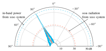
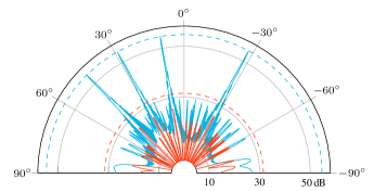
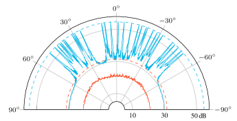
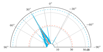
Figure 2 illustrates how the in-band and oob beampatterns from a large array differ in line-of-sight. It also shows how they compare to an omnidirectional siso system, whose transmit signal has the same aclr as the transmit signals of the array, and whose transmit power is chosen such that all users receive the same in-band power. We see that there are bad directions, in which the oob radiation is stronger, and that there can be good directions, in which there is very little oob radiation.
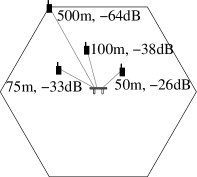
Note that the radiation pattern in a multi-user case can be similar to the single-user case with only one visible beam. This happens when users experience very different path losses, which is common in a cellular system as shown in Figure 2. Then most of the radiated power can be directed towards the weakest user, in order to give the same quality of service to all users.
1 user, |
4 users, |
15 users, |
30 users, |
4 users distributed as in the sketch |
|
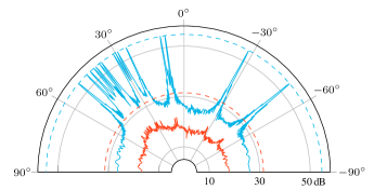
When the array serves one user in line-of-sight (one spatial component), the signal envelope is the same at each antenna, which creates distortion that has the same beamforming as the in-band signal. There is therefore one direction, towards the served user, with oob radiation as bad as the siso system. All other directions are suppressed in the same way as the in-band signal. If the array serves multiple users (multiple spatial components), there are many bad directions. All of the bad directions are better than in the siso system however, where the oob radiation in any direction always is greater than or equal to the oob radiation of the array in the worst direction. When the number of served users increases, the bad and good directions disappear—all directions become equally good—and the oob radiation is significantly lower than in the siso system.
Just as the frequencies of the intermodulation products of a nonlinearity are combinations of the frequencies of the constituent components of the input signals, the spatial characteristics (the angle of departure in line-of-sight) of these products are combinations of the spatial characteristics of the input components. When the number of “spatial intermodulation products”, which can be shown to grow super-linearly in the number of spatial components in the input signal (number of users times the number of channel taps), grows greater than the spatial dimension (i.e. the number of antennas), then the distortion becomes increasingly isotropic.
The array in Figure 2 is a linear array with uniform antenna spacing of half a wavelength. It creates radiation patterns without significant grating lobes, except for the back lobes on the opposite side of the array. Other array geometries with grating lobes would cause the oob radiation to also radiate in the directions corresponding to those lobes. Since arrays with grating lobes in general also have narrower beams, the probability that a victim ends up in a beam of oob radiation is not significantly changed by different array geometries. Furthermore, the oob radiation in the directions of the grating lobes is still smaller than in the siso system. The radiation patterns studied in Figure 2 have the same basic appearance for any array type.
It is important to note that the array has no directions with worse oob radiation than the siso system. Since the in-band signal is beamformed to maximize its array gain, the oob radiation can at most obtain the same array gain as the in-band signal, and therefore the oob radiation is never stronger than in a siso system with the same aclr .
There is a small risk that a victim stands in a bad direction, especially if few users are served. The worst case is when a system serves one user and a victim stands in the same direction as that user. In this case, the victim receives as much oob radiation as from the siso system. The probability that an unfortunate victim stands in a bad direction becomes smaller as the number of antennas grows large, and the main lobe becomes increasingly narrow.
Based on this discussion, we make the following observations:
-
(i)
Keeping the same aclr requirements as in legacy systems would guarantee that no victim, not even the most unfortunate one, receives more oob power than from a legacy system. The aclr requirement does not have to be more stringent.
-
(ii)
If multiple users are served, the oob radiation can be treated as isotropic and the legacy aclr requirement can be relaxed.
-
(iii)
If a single user is served, the oob radiation is highly directive and the legacy aclr requirement can be relaxed if a certain probability is allowed that an unfortunate victim ends up in an oob lobe. This probability is increasingly small when the array is large.
4 Static Channels with Isotropic Fading
The received oob radiation varies with the channels to the victim and the served users. If the channel changes slowly or if the victim systems is sensitive to outage, e.g. when there are high reliability or latency requirements, the oob radiation has to be constrained during every channel realization. Much of what was said in Section 3 about static line-of-sight channels carries over to slowly changing frequency-selective channels with isotropic fading. One difference, however, comes from the larger number of propagation paths.
A consequence of the multipath propagation of wideband signals is frequency-selective fading. The multiple taps of the channel make the oob radiation less directive in much the same way as serving more users. Therefore, also when a single user is served by the array, the most unfortunate victim of oob radiation still receives much less power than from a siso system.
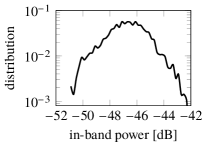
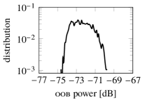
Another advantage of the large array as compared to the siso system is channel hardening. Figure 3 shows the distribution of the received oob power at a random victim for different systems with transmit signals with the same aclr . It can be seen how constructive and destructive superposition, which is the result of multipath propagation, can result in large variations in oob radiation in the siso system. In a large array, however, channel hardening eliminates variations due to multipath propagation; variations only come from the directivity of the transmission. Just like in the line-of-sight system, the oob radiation of the single-user system is slightly directive and there is a small risk that a victim will receive more oob radiation than on average—in Figure 3, the probability to receive 3 dB more oob radiation than on average is 0.001. The directivity becomes less prominent when the number of significant users, i.e. users to whom a significant part of the transmit power is directed, is increased. With ten equally significant users, the vertical slope in Figure 3 shows that the oob radiation is practically isotropic. As noted in Section 3, however, large differences in path loss between the served users can require that most of the power is beamformed to a single user if all users are to enjoy the same quality of service. The single-user case is therefore representative also for many multi-user systems.
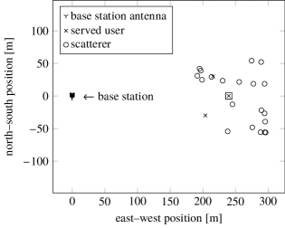
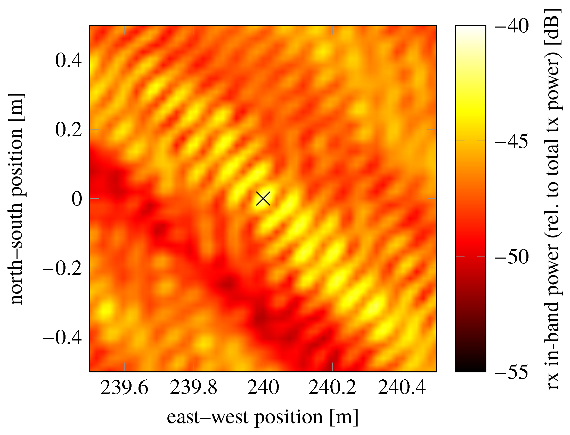
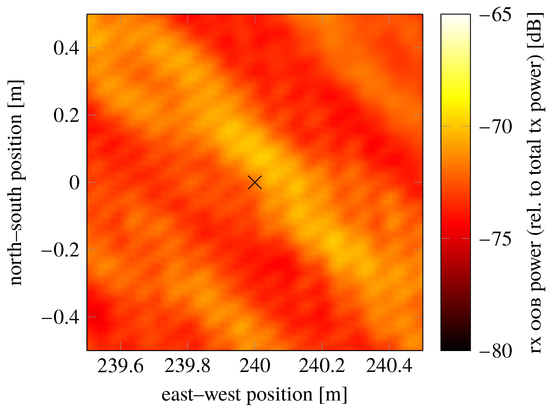
In Figure 4, a simple scattering environment is illustrated. Scattering centers have been randomly dropped over an area and a uniform linear array with 100 antennas beamforms to three users inside the area. It can be seen that the directivity, or the array gain, of both the in-band and the oob signal varies with location. The variations, however, are much smaller for the oob signal because of its isotropy and because of channel hardening.
map
in-band power
oob power
5 Mobile Channels with Isotropic Fading
When the disturbing oob power can be averaged over many channel fades and all gains can be averaged over the fading, the victim can protect its operation from outage as long as the average received oob power is limited. In a mobile channel with isotropic fading, we have to distinguish between two cases:
- Case 1
-
the channels to the served user and to the victim are uncorrelated,
- Case 2
-
the channels are correlated.
Whereas Case 1 is the common one, Case 2 is perceivable when the served user and victim are served by different transmitters but share the same antenna and their channel is not frequency selective enough to decorrelate the channels of the two bands.
In Case 1, the average oob power that the victim receives, normalized by the path loss, is determined by the total radiated oob power at the transmitter, both for legacy systems and for large arrays. Given a transmit power, an aclr constraint thus limits how much oob power that a victim receives on average, which is enough to protect the operation of the victim. When the correlation is high, the oob radiation of Case 2 has to be analyzed as in the static case, since the oob radiation to the victim then experiences an array gain also when averaged over many fades.
Since less radiated power is required from a large array than from a legacy system for a given received in-band power, the average received oob power is also correspondingly lower when the transmit signals of two systems have the same aclr , which was seen in Figure 3. The aclr requirement should therefore be relaxed for the large array as compared to the legacy system by the same amount, by which the total radiated power is reduced. Since the in-band array gain grows with the number of antennas of the array, the aclr requirement can be relaxed more, the more antennas the array has. However, the radiated power also increases with the number of served users and varies slightly depending on the employed beamforming technique. Therefore the aclr requirement has to be specified in terms of these system parameters or set according to the worst scenario, in which the most oob power is radiated.
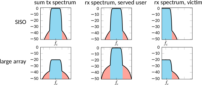
Figure 5 shows the average power spectral densities of two example scenarios; the path loss has been normalized for simplicity. In the legacy siso case, highly linear hardware gives the transmitted signal a good aclr . Consequently, the served user receives a sufficient amount of in-band power and, at the same time, the victim who operates in the adjacent band receives little disturbing power. In the large array case, the transmitted signal has an aclr that is seemingly worse because less linear hardware is used; the transmitted power is also smaller. Because the signal is beamformed, however, the served user still receives a sufficient amount of in-band power. At the same time, the victim receives little disturbing power on average. This example shows that the aclr constraint of siso systems cannot directly be applied to arrays. The array gain of the in-band signal at the served users and the distribution of the oob signal at the victim also have to be taken into account.
6 How to Measure OOB Radiation
To mitigate the disturbance of other systems, most communication standards, such as wcdma, lte, wifi, and national regulatory bodies, such as FCC (the Federal Communications Commission) in the United States, limit the amount of permitted oob radiation. This is usually done by enforcing a constraint on the aclr of the transmit signal and a maximum power level for the emitted oob signal. For example, in lte, the aclr has to be better than 45 dBc or the absolute power spectral density of the signal in a wide outdoor area has to be lower than 13 dBm/MHz outside the allocated band, whichever is less stringent.
Two quantities are of interest: the useful in-band power at the served users, and the disturbing oob power at the victim. Under the assumption that both powers are attenuated equally much, the aclr of the transmitted signal is the ratio between the two. When the transmitter has a large array, the array gain will influence the received powers. We have seen that, when the powers can be averaged over many coherence intervals, the disturbing oob radiation is isotropic, while the useful in-band signal gets a large array gain. The aclr regulations used in legacy systems that do not consider array gain are therefore unnecessarily stringent, and can be relaxed for large arrays by an amount equal to the array gain of the in-band signal.
In static scenarios, a constraint might have to include a safety margin to protect sensitive victims from the case when the array gain of the oob radiation is significant. Because the oob array gain is smaller than the in-band array gain and the transmit power is lower than in legacy systems, the aclr constraint with added safety margin is still relaxed compared to legacy systems. For isotropic scattering, the safety margin can be read off from percentiles, like the one in Figure 3; it is often small and can be neglected however. In a line-of-sight channel, this margin can be substantial and can be measured by the served users.
Since oob radiation is isotropic in many cases, a more practical way to put the oob constraint could be to regulate the total radiated oob power in relation to the in-band power. FCC [13, Sec. IV.G.3] has also mentioned the possibility to measure oob radiation “over the air”, i.e. to take measurements at selected positions around the transmitting array and draw conclusions about the received oob power everywhere else from those measurements. For practical reasons, over-the-air measurements is most likely the only alternative for mmWave arrays.
One way to do that, in analogy to the legacy aclr measure, would be to set up a controlled environment and let the array beamform a signal to a served user in its normal operational mode. Then measure the useful in-band power at the served user and the disturbing oob power at a reference victim. The ratio between the two—the array aclr —can then be constrained in the same way as in legacy systems. The reason for employing such a strategy would be to avoid measuring directly on each of the individual transmit signals in the array and to make the constraint independent of the number of antennas and other system parameters.
If the same transmitted power is used as in legacy systems, the oob constraint cannot necessarily be relaxed as compared to legacy systems. An stricter oob constraint, however, is only necessary if there is a non-negligible risk that the array gain of the disturbing oob radiation at a victim is large. We have shown how this risk is increasingly small for large arrays. Furthermore, as discussed in Section 2, to use the same transmit power as in a legacy system is seldom necessary.
7 Conclusion
We have shown how a victim, on average, receives less oob radiation from base stations with large arrays than from legacy systems with the same aclr requirement for a given received snr requirement. In the worst case, the victim receives the same amount of oob radiation as from the legacy system. However, this worst case event occurs only when most of the transmitted power is directed towards a single user whose channel impulse response consists of taps that are all linearly dependent, and then only with a small probability. Furthermore, the probability grows increasingly small as the number of antennas grows large.
This conclusion relies on the assumption that the channel to the victim is uncorrelated to the channel of the served users. If that is not true, for example if the victim shares its antenna with one of the served users, the probability that the victim receives the same amount of oob radiation as from the legacy system can increase significantly. However, the oob radiation is never greater than from the legacy system.
When the dimension of the space spanned by the channel vectors of the served users is large, which happens with high probability when the product of the number of users and number of channel taps is large, the oob radiation becomes close to isotropic. This makes it redundant to measure the radiation pattern for each setup, which simplifies the measurement of oob radiation.
This suggests that relaxed aclr and linearity constraints can be used for the hardware in large arrays. To set appropriate linearity requirements on the hardware is important, because it will be decisive for how future radio equipment will be designed. Especially since it is desirable to build large arrays without high-end hardware or advanced compensation techniques, which become impediments as the number of radio chains grows [14, 15]. The linearity requirement will determine what amplifier architectures, digital-to-analog converters etc. that have to be employed. It will also influence what signal processing is required, such as predistortion, par reduction and low-par precoding. Power efficiency, system complexity, cost and size of future communication systems will all be affected by the way oob radiation from large arrays is regulated.
References
- [1] F. Boccardi, R. W. Heath, Jr., A. Lozano, T. L. Marzetta, and P. Popovski, “Five disruptive technology directions for 5G,” IEEE Commun. Mag., vol. 52, no. 2, pp. 74–80, Feb. 2014.
- [2] T. L. Marzetta, E. G. Larsson, H. Yang, and H. Q. Ngo, Fundamentals of Massive MIMO. Cambridge University Press, 2016.
- [3] K. G. Gard, H. M. Gutierrez, and M. B. Steer, “Characterization of spectral regrowth in microwave amplifiers based on the nonlinear transformation of a complex Gaussian process,” IEEE Trans. Microw. Theory Tech., vol. 47, no. 7, pp. 1059–1069, Jul. 1999.
- [4] M. H. Ng, S.-D. Lin, J. Li, and S. Tatesh, “Coexistence studies for 3GPP LTE with other mobile systems,” IEEE Commun. Mag., vol. 47, no. 4, pp. 60–65, Apr. 2009.
- [5] W. Sandrin, “Spatial distribution of intermodulation products in active phased array antennas,” IEEE Trans. Antennas Propag., vol. 21, no. 6, pp. 864–868, Nov. 1973.
- [6] C. Hemmi, “Pattern characteristics of harmonic and intermodulation products in broadband active transmit arrays,” IEEE Trans. Antennas Propag., vol. 50, no. 6, pp. 858–865, Jun. 2002.
- [7] Y. Zou, O. Raeesi, L. Antilla, A. Hakkarainen, J. Vieira, F. Tufvesson, Q. Cui, and M. Valkama, “Impact of power amplifier nonlinearities in multi-user massive MIMO downlink,” in Proc. IEEE Globecom Workshops, Dec. 2015, pp. 1–7.
- [8] C. Mollén, U. Gustavsson, T. Eriksson, and E. G. Larsson, “Out-of-band radiation measure for MIMO arrays with beamformed transmission,” in Proc. IEEE Int. Conf. Commun., May 2016, pp. 1–6.
- [9] S. Mohammed and E. G. Larsson, “Constant-envelope multi-user precoding for frequency-selective massive MIMO systems,” IEEE Wireless Commun. Lett., vol. 2, no. 5, pp. 547–550, Oct. 2013.
- [10] O. Edfors and F. Tufvesson, “MaMi channel characteristics: Measurement results,” https://mammoet-project.eu/publications-deliverables, Massive MIMO for Efficient Transmission (MAMMOET), Project Deliverable D1.2, Jun. 2015, online: accessed 2016-10-26.
- [11] M. Peter, K. Sakaguchi, S. Jaeckel, S. Wu, M. Nekovee, J. Medbo, K. Haneda, S. L. H. Nguyen, R. Naderpour, J. Vehmas, F. Mani, A. Bamba, R. D’Errico, M. Rybakowski, J.-M. Conrat, A. Goulianos, P. Cain, M. Rumney, M. Dieudonne, H. Wang, and M. Kottkamp, “Measurement campaigns and initial channel models for preferred suitable frequency ranges,” https://bscw.5g-mmmagic.eu/pub/bscw.cgi/93650, Millimetre-Wave Based Mobile Radio Access Network for Fifth Generation Integrated Communications (mmMagic), Project Deliverable H2020-ICT-671650-mmMAGIC/D2.1, Mar. 2016, online: accesed 2016-10-26.
- [12] C. Mollén. (2016, Nov.) Source code for the analysis of out-of-band radiation from large arrays. [Online]. Available: https://github.com/OOBRadMIMO/NumericalResults
- [13] “FCC 16-89 report and order and further notice of proposed rulemaking,” https://www.fcc.gov/document/spectrum-frontiers-ro-and-fnprm, Federal Communications Commission, Tech. Rep., Jul. 2016, online: accessed 2016-10-26.
- [14] U. Gustavsson, C. Sanchez Perez, T. Eriksson, F. Athley, G. Durisi, P. N. Landin, K. Hausmair, C. Fager, and L. Svensson, “On the impact of hardware impairments on massive MIMO,” in Proc. IEEE Global Commun. Conf., Dec. 2014.
- [15] E. Björnson, M. Matthaiou, and M. Debbah, “Massive MIMO with non-ideal arbitrary arrays: Hardware scaling laws and circuit-aware design,” IEEE Trans. Wireless Commun., vol. 14, no. 8, pp. 4353–4368, Aug. 2015.