Low energy Ne ion beam induced-modifications of magnetic properties in MnAs thin films
Abstract
Investigations of the complex behavior of the magnetization of manganese arsenide thin films due to defects induced by irradiation of slow heavy ions are presented. In addition to the thermal hysteresis suppression already highlighted in M. Trassinelli et al., Appl. Phys. Lett. 104, 081906 (2014), we report here on new local magnetic features recorded by a magnetic force microscope at different temperatures close to the characteristic sample phase transition. Complementary measurements of the global magnetization measurements in different conditions (applied magnetic field and temperatures) enable to complete the film characterization. The obtained results suggest that the ion bombardment produces regions where the local mechanical constraints are significantly different from the average, promoting the local presence of magneto-structural phases far from the equilibrium. These regions could be responsible for the thermal hysteresis suppression previously reported, irradiation-induced defects acting as seeds in the phase transition.
I Introduction
Manganese arsenide (MnAs) is one of the most promising materials for the magnetic refrigeration Gutfleisch et al. (2011); Manosa et al. (2013); Moya et al. (2014). It is in fact characterized by a giant magnetocaloric effect close to room temperature that makes it a very attractive material for common refrigeration applications. The giant magnetocaloric effect of MnAs is related to the large entropy change during the first-order magneto-structural transition close to room temperature ( K) between a ferromagnetic -phase with hexagonal structure (NiAs-type) and the paramagnetic -phase with orthorhombic structure (MnP-type).
The possibility of epitaxial growth on standard semiconductors such as GaAs make MnAs thin films interesting also for spintronic research Däweritz (2006) and magneto-elastic applications Duquesne et al. (2012); Marangolo et al. (2014). The epitaxial strain disturbs the phase transition and leads to the phase coexistence over a large range of temperatures (280–320 K). The refrigeration power associated to the giant magnetocaloric properties does not change but is spread out on the coexistence temperature interval Mosca et al. (2008). In this range, an alternating structure of ridges ( phase) and grooves ( phase) organized in stripe-shaped domains parallel to MnAs[0001] is created to minimize the elastic energy due to the epitaxy. The periodicity of the ridge-groove structure is constant with the temperature and is related to the thickness of the sample by the relation Kastner et al. (2002); Kaganer et al. (2002); Breitwieser et al. (2009).
The richness of the MnAs thin films properties results in a complex dependency of the magneto-structural properties on the external temperature, applied magnetic field and constraints. In the past years, many studies have been dedicated to the characterization of epitaxial MnAs films Kaganer et al. (2000, 2002); Kastner et al. (2002); Däweritz et al. (2003, 2004); Lindner et al. (2004); Ploog (2004); Adriano et al. (2006); Däweritz (2006); Garcia et al. (2007); Breitwieser et al. (2009). In particular, magnetic force microscopy (MFM) appeared to be a very useful tool to study the local magnetic properties as a function of different parameters such as: growing conditions Schippan et al. (2000); Däweritz and Herrmann (2007), film thickness Daweritz et al. (2005); Manago et al. (2006); Ryu et al. (2006), temperature Plake et al. (2003); Mohanty et al. (2003a, b); Coelho et al. (2006), applied magnetic field Engel-Herbert et al. (2005, 2006) and more recently, applied magnetic field and temperature at the same time Kim et al. (2011). In addition to the above investigations based on the out-of-plane magnetic leak field detection, measurement of the in-plane magnetic component imaging has been obtained on cleavage edges Rache Salles et al. (2010).
Recently it has been demonstrated that slow ions bombardment can interestingly change the thin film properties Trassinelli et al. (2014); Cervera et al. (2015). New irradiation-induced defects facilitate the nucleation of one phase with respect to the other one in the first-order magneto-structural MnAs transition, with a consequent stable suppression of the thermal hysteresis without any significant perturbation of the other properties. Transition temperature, saturation magnetization and structural properties are unchanged and, more importantly, the giant magnetocaloric properties of the film is maintained. When present, the thermal hysteresis induces energy losses in the thermal cycles that use giant magnetocaloric material for refrigeration. Its suppression opens new perspectives for the magnetic refrigeration applications based on MnAs-type material.
The origin of the hysteresis removal being not clear, we present here additional investigations on magnetic properties of the irradiated films under different temperatures and applied field conditions, in particular with the study of the local out-of-plane magnetic field via MFM imaging. These studies provide new findings that allow to elucidate many aspects of the ion bombardment effects and also reveal new phenomena.
II Film production and irradiation
All MnAs films considered here have a thickness of 150 nm, are monocrystalline and are issued from the same growth obtained by molecular beam epitaxy (MBE) on GaAs(001) substrate. The deposited MnAs is oriented with the -MnAs and -MnAs axis parallel to GaAs. Details on the growth process can be found in Ref. 10.
The samples are irradiated with a Ne9+ ion beam at the SIMPA facility Gumberidze et al. (2010) (French acronym for highly charged ion source of Paris). The ion kinetic energy is set at 90 keV (4.5 keV/u) with an incidence angle of 60∘ with respect to the normal of the sample surface. These settings were chosen for having the average penetration depth of ions corresponds to the half-thickness of the MnAs film Ziegler et al. (2008), without any penetration into the substrate. In these conditions, the maximization of the effect arising from the ion irradiation is expected Zhang et al. (2004). For the ion energy range considered here, the ion-induced defects are principally produced by the nuclear stopping power with a series of binary collisions between the projectile and the target atoms Ziegler and Biersack (1985); Averback and De La Rubia (1998). Target recoil atoms can also produce secondary collisions with the creation of collision cascades that involve many target atoms. For one incident atom, about 500 target atom displacements are expected in our conditions.
In the present paper, we focus our investigation on one particular sample that received a fluence ions cm-2 and mainly reflect the effects of the ion bombardment in MnAs thin films. This sample is systematically compared to a non-irradiated one called reference or pristine sample. More details about the irradiation process can be found in Ref. 31 and 38.
III Results and discussion
III.1 Measurements of the pristine sample
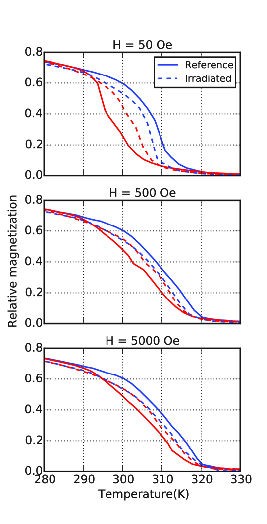
The magnetization dependency of the pristine sample with the temperature is mainly driven by the ratio between the and phases. For weak applied fields, the reciprocal alignment of the different magnetic domains in the ferromagnetic phase regions, separated by the paramagnetic phase, plays also an important role. This effect can be observed in the relative magnetization recorded at different increasing and decreasing values of the temperature shown in Fig. 1. The sample magnetization has been recorded by a Quantum Design MPMS-XL SQUID magnetometer with a sweep rate of K/min with 1 T magnetic field applied along the MnAs easy axis . As visible in Fig. 1, the thermal hysteresis is smaller for intense fields than for weak fields, with K for and 5000 Oe and K for Oe. This is probably due to the more difficult propagation of the domain walls of ferromagnetic regions separated by paramagnetic regions Tortarolo et al. (2012).
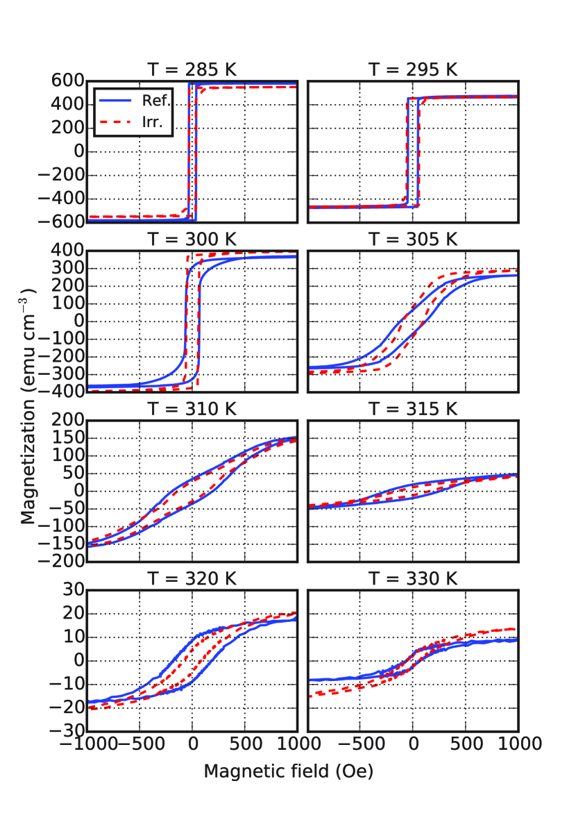
This interplay between magnetic domains in spatially separated regions is also responsible of the high coercivity field for the temperatures where the two phases are coexisting (300–320 K). This is well visible from the sample magnetization measurements along the MnAs easy axis as function of the magnetic field (between T) obtained in a VSM magnetometer (Quantum Design PPMS 9T) at different temperatures. Note that before each magnetic cycle measurement, the history of the sample is erased by magnetic depolarization at K to avoid the production of experimental artifacts like the so-called colossal magnetocaloric effect Caron et al. (2009); Tocado et al. (2009). As we can observe in the Fig. 2, the domain direction flip takes place at Oe for low temperatures, but increases up to Oe during the phase coexistence. This singular behavior is characteristic of MnAs thin films and it has already observed previously Ney et al. (2004); Steren et al. (2006); Cervera et al. (2015) and successfully modeled Engel-Herbert and Hesjedal (2008) in the past.
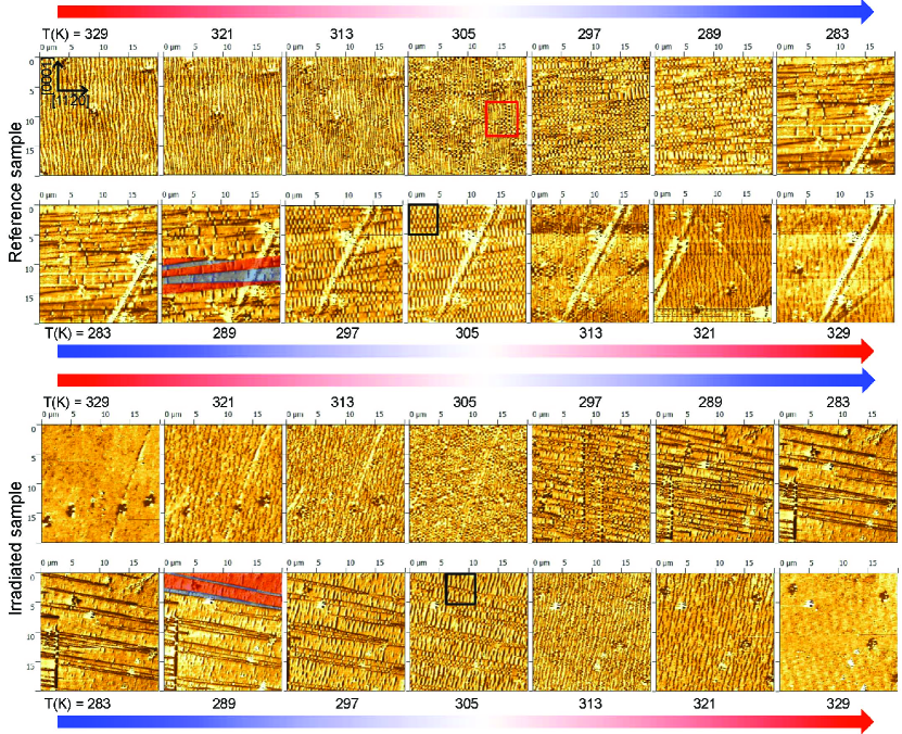
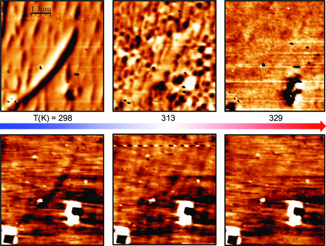
The features of the MFM images obtained at different temperatures and no external field (Fig. 3, top) reflect the complicate interplay between magnetic domains. The direct observation of the - and -phase regions layout is obtained with a MFM (Bruker Multimode AFM microscope equipped with a magnetic tip coated with Co/Cr, model MESP, with a lift height of 20 nm) equipped with a Peltier regulator to adjust the temperature. The measurement is performed under normal atmospheric pressure and it was limited to temperatures higher than the dew point ( K) to avoid water condensation on the sample. The different images are acquired starting at decreasing and subsequently increasing sample temperatures, from the initial value of K. During the temperature change, spatial drifts of the sample did not allow for the measurement of very high quality images. In particular it did not allow for a perfect correspondence between the different spatial regions in of a given area.
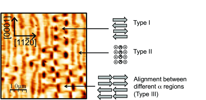
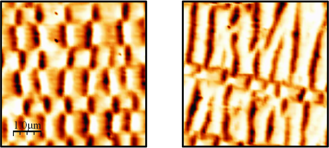
Because of the absence of applied external field, MFM images correspond to the visualization of the out-of-plane magnetic field component from -phase regions separated by -phase regions. Different temperatures correspond to different typical sizes of the -phase regions that favor different domain types that are presented in Fig. 4 (see also Plake et al. (2003); Engel-Herbert et al. (2005); Coelho et al. (2006); Däweritz and Herrmann (2007); Kim et al. (2011)). When the ferromagnetic regions are sufficiently extended, the magnetic domains are normally aligned along the easy magnetization axis MnAs with the formation of type-I magnetic domains, with meander-like contrast. We can also have entire portions of -phase regions in a single domain state (type-III domains) aligned to other ferromagnetic regions orientation across different -phase regions, forming what we call macro-domains. For very small -phase regions, type-II domains, with magnetic moment perpendicular to the surface, are present.
As visible in Fig. 3, when coexistence of and phases exists, those regions are elongated in fact along the MnAs[0001] direction, which is perpendicular to the easy magnetization axis (MnAs). Point-like features, well visible at high temperatures, are due to growth process defects and they have a correspondence in the topography images. Similarly, the diagonal line in the lower row of the reference sample images is due to a topological defect.
Because of the reduced extension of -phase regions, type-II domains are dominant at high temperatures. When more extended regions of -phase are present ( K), type-I domains start to appear and form macro-domains. As shown in Fig. 3, large domains are recognizable as elongated zones aligned width the easy magnetization axis MnAs exhibiting black-white stripes alternation typical of MnAs MFM images during the phase coexistence Däweritz (2006). To facilitate the readability of the MFM images, we indicate in the image relative to the reference sample at K in Fig. 3 the extension of the macro-domains of opposite magnetization by means of over-imposed blue and red areas. The limits between different macro-domains are easily recognizable by the flip of the MFM phase contrast of the stripes. At lower temperatures ( K), -phase regions disappear completely on large portions of the films leaving MFM image regions without any contrast.
III.2 Effect of the ion irradiation
Irradiation of the thin film with slow ions produce new defects in the MnAs crystal. As reported in Refs. 31; 32, these new defects act as nucleation seeds of one phase with respect to the other during the magneto-structural transition leading to the elimination of the thermal hysteresis.
Investigations with X-ray diffraction for possible structural changes show that the and phases structure of irradiated samples, up to a fluence of ions cm-2, are unchanged as presented in Refs. 31; 32. The film remains monocrystalline and only a small increase of the average lattice spacing is noticed (less than 0.3% for a fluence of ions cm-2).
In addition to the thermal hysteresis suppression previously reported, irradiation-induced modifications are additionally characterized by magnetometry measurements for different applied magnetic field values () and temperatures (), and by MFM imaging. These measurements provide new insights on the nature of the bombardment damages. As we can see in the magnetization measurements as a function of the temperature in Fig. 1, for Oe, the major difference between the pristine and irradiated samples is the suppression of the thermal hysteresis without variation of the critical temperature of the transition. This is not true when a magnetic field of 50 Oe is applied. There, the thermal hysteresis is still present and is K (Fig. 1). Nevertheless, we note that the difference between has a constant value of about K for any applied field. This suggests that for Oe, the non-zero value of is not due to additional pinning caused by irradiation-induced defects but most likely to an intrinsic property of MnAs/GaAs film.
More information can be extracted from the magnetization measurements as a function of the applied magnetic field at different temperatures (Fig. 2). No major differences in the shape of between reference and irradiated samples are visible except at the temperatures and 305 K where the inflection point position or the slope changes. In these cases, referring to Fig. 1, one can deduce that the phase ratio plays a role due to the thermal hysteresis.
As previously reported Trassinelli et al. (2014); Cervera et al. (2015), the ion irradiation does not affect the coercivity field values. Changes of the saturation magnetization are however visible. At K the absolute value of the magnetization of the irradiated sample is slightly lower than in the reference one. This is also visible in the measurement in Fig.1. But no noticeable difference of the magnetic saturation is visible at lower temperature ( K). A possible explanation of this behavior is the presence of residual -phase regions when only the phase should be present. This hypothesis is confirmed by the MFM images that are discussed in the next paragraph. Finally it is worth mentioning that thin film magnetization reduction under action of ion irradiation is also commonly observed in samples that exhibit a second-order magnetic transition because of irradiation-induced crystal structure rearrangement and change of the dipole-dipole interaction Weller et al. (2000); Kaminsky et al. (2001); Zhang et al. (2003); Fassbender et al. (2006); Fujita et al. (2010); Cook et al. (2011); Tohki et al. (2012); Oshima et al. (2013). However, compared to the results presented here, these past studies involved much higher ion fluences ( ions cm-2) that, differently than in our case, can substantially change the sample structure and composition.
Additional insights can be extracted from the magnetic force microscope images and topography of the sample. The topography imaging does not show any differences between the pristine and irradiated sample. This is not surprising because the relative low-value of the potential energy carried by the ions does not allow the formation of new surface defects Aumayr et al. (2011). On the other hand, compared to the reference sample, the MFM images (Fig. 3) of the irradiated sample present several differences:
-
1.
there is a qualitatively different dependency on the temperature,
-
2.
they are characterized by an irregular pattern of the phase region disposition,
-
3.
at low temperature, persisting -phase regions are observed.
Point 1 is due to the reduction or suppression of the thermal hysteresis that anticipates the appearance of one phase with respect to the other one in the irradiated sample compared to the pristine one. As discussed above, this reduction is caused by the easier nucleation of the phases due the irradiation-induced defects. These defects disturb also the regular phase disposal, point 2, as clearly visible in Fig. 5. This phenomenon is similar to the effect of defects produced during the film growth that are observed to induce Y-shape stripe bifurcation in well defined positions (corresponding to the defect positions) Däweritz et al. (2003); Breitwieser et al. (2009).
Point 3 is particularly interesting. At low temperature, we can see in Fig. 3 that the macro-domains are disturbed by linear regions where the phase is persisting. These regions are recognizable by a local contrast of the MFM phase that develop along lines and by a depression of a few nm in the topography lines (not shown) due to the smaller cell volume of the phase Däweritz (2006); Breitwieser et al. (2009). These regions are particularly visible in the image relative to K approaching from higher temperatures in Fig. 3. For lower values, only one vertical -phase region is persisting, down to the lowest reached temperature of 283 K. This effect is even more evident when the sample is cooled from about 350 K with an external field of about 5000 Oe before imaging it with the MFM. As we can see in Fig. 6, where a m2 of the irradiated sample at the temperature of 298 K prepared in this way is shown, a -phase diagonal region is visible in the MFM image together with a depression (of about 5 nm) in the topography image. When increasing temperature, this -phase region is less and less contrasted with respect to the surrounding area in both MFM and topography images due to the global transition to the phase.
The presence of the phase at this low temperature may be due to local constraints induced by the ion irradiation. Past experimental and theoretical studies on ion–matter interaction show that, at this ion energy regime, collision cascades can lead to the formations of spatially localized regions rich in interstitial atoms or vacancies Averback and De La Rubia (1998); Nordlund et al. (1999); Kim et al. (2012); Lu et al. (2016). Interstitial-rich regions could cause an increase of the local high internal pressure favoring the presence of the phase that is characterized by a volume 2% larger than the phase. In connection to the persistence of small -phase regions, the sample magnetization is expected to be reduced with respect to the reference sample, which is the case as visible in the magnetometry measurements in Fig. 1. At very low temperature ( K) not monitored with the MFM, irradiated samples have practically the same saturation magnetization than pristine samples Trassinelli et al. (2014) suggesting that these “frozen” -phase regions are thus suppressed.
Similarly, the presence of surviving -phase regions at high temperatures seems plausible, but is difficult to observe due to the complex magnetic images caused by the transition between type-I and type-II magnetic domains. In correlation with vacancies-rich regions, a local low internal pressure is expected that can favor the presence of phase regions. The high magnetization of irradiated samples at K in the curve (Fig. 2) could be an indication of the persistence of -phase regions at high temperatures. This persistence could be the reason for the presence of large macro-domains with the same orientation contrary to what happen in the pristine sample (Fig. 3, ). Remaining -phase regions with a defined magnetic orientation could in fact seed the nucleation of domains with a specific direction (before the series of observation on the MFM the samples are initially cooled in presence of a persisting magnetic field of about 5000 Oe).
Recent studies on nanoindentation in NiMnGa Heusler alloy films Niemann et al. (2016) show that local constrains can favor the nucleation of one phase into the other phase in the characteristic first-order phase transition. Similarly, here local regions of and phase, which are persisting at a temperature respectively higher and lower than the transition temperature, could be at the origin of the thermal hysteresis suppression making easier the transition of one phase into the other phase.
IV Conclusions
We report new investigations on the effect of ion bombardment on manganese arsenide thin films. These studies confirm that the thermal hysteresis is suppressed when an intense magnetic fields is applied due to local irradiation-induced defects. This is not the case for weak external field. At 50 Oe the surviving thermal hysteresis seems related to the intrinsic properties of MnAs/GaAs films and in particular to the high coercivity field value during the phase coexistence. The local effects of the new defects are well visible on the MFM images where the self-organization of MnAs phases is disturbed and where -phase regions persist in specific spots at temperatures well below the phase transition temperature. This is in agreement with the observed magnetization of the irradiated sample which is lower than the pristine magnetization for while at lower temperature, i.e. K, the magnetization is the same for the two samples. Similarly, there are indications that small -phase regions could resist to temperatures higher than the phase transition temperature. Nevertheless the nature of the irradiation-induced defects is still not completely revealed and it will require future investigation with different projectile masses and collision conditions.
Acknowledgments
This work was partially supported by French state funds managed by the ANR within the Investissements d’Avenir program under reference ANR-11-IDEX-0004-02, and more specifically within the framework of the Cluster of Excellence MATISSE led by Sorbonne Universités. V. Gafton acknowledges support from the strategic grant POSDRU/159/1.5/S/137750, Project, “Doctoral and Post-doctoral programs support for increased competitiveness in Exact Sciences research” co financed by the European Social Found within the Sectoral Operational Program Human Resources Development 2007-2013
References
- Gutfleisch et al. (2011) O. Gutfleisch, M. A. Willard, E. Brück, C. H. Chen, S. G. Sankar, and J. P. Liu, Adv. Mater. 23, 821 (2011).
- Manosa et al. (2013) L. Manosa, A. Planes, and M. Acet, J. Mater. Chem. A 1, 4925 (2013).
- Moya et al. (2014) X. Moya, S. Kar-Narayan, and N. D. Mathur, Nature Mater. 13, 439 (2014).
- Däweritz (2006) L. Däweritz, Rep. Prog. Phys. 69, 2581 (2006).
- Duquesne et al. (2012) J. Y. Duquesne, J. Y. Prieur, J. A. Canalejo, V. H. Etgens, M. Eddrief, A. L. Ferreira, and M. Marangolo, Phys. Rev. B 86, 035207 (2012).
- Marangolo et al. (2014) M. Marangolo, W. Karboul-Trojet, J.-Y. Prieur, V. H. Etgens, M. Eddrief, L. Becerra, and J.-Y. Duquesne, Appl. Phys. Lett. 105, 162403 (2014).
- Mosca et al. (2008) D. H. Mosca, F. Vidal, and V. H. Etgens, Phys. Rev. Lett. 101, 125503 (2008).
- Kastner et al. (2002) M. Kastner, C. Herrmann, L. Daweritz, and K. H. Ploog, J. Appl. Phys. 92, 5711 (2002).
- Kaganer et al. (2002) V. M. Kaganer, B. Jenichen, F. Schippan, W. Braun, L. Däweritz, and K. H. Ploog, Phys. Rev. B 66, 045305 (2002).
- Breitwieser et al. (2009) R. Breitwieser, F. Vidal, I. L. Graff, M. Marangolo, M. Eddrief, J. C. Boulliard, and V. H. Etgens, Phys. Rev. B 80, 045403 (2009).
- Kaganer et al. (2000) V. M. Kaganer, B. Jenichen, F. Schippan, W. Braun, L. Däweritz, and K. H. Ploog, Phys. Rev. Lett. 85, 341 (2000).
- Däweritz et al. (2003) L. Däweritz, M. Kästner, T. Hesjedal, T. Plake, B. Jenichen, and K. H. Ploog, J. Cryst. Growth 251, 297 (2003).
- Däweritz et al. (2004) L. Däweritz, L. Wan, B. Jenichen, C. Herrmann, J. Mohanty, A. Trampert, and K. H. Ploog, J. Appl. Phys. 96, 5056 (2004).
- Lindner et al. (2004) J. Lindner, T. Toliński, K. Lenz, E. Kosubek, H. Wende, K. Baberschke, A. Ney, T. Hesjedal, C. Pampuch, R. Koch, L. Däweritz, and K. H. Ploog, J. Magn. Magn. Mater. 277, 159 (2004).
- Ploog (2004) K. H. Ploog, J. Cryst. Growth 268, 329 (2004).
- Adriano et al. (2006) C. Adriano, C. Giles, O. D. D. Couto, M. J. S. P. Brasil, F. Iikawa, and L. Daweritz, Appl. Phys. Lett. 88, 151906 (2006).
- Garcia et al. (2007) V. Garcia, Y. Sidis, M. Marangolo, F. Vidal, M. Eddrief, P. Bourges, F. Maccherozzi, F. Ott, G. Panaccione, and V. H. Etgens, Phys. Rev. Lett. 99, 117205 (2007).
- Schippan et al. (2000) F. Schippan, G. Behme, L. Däweritz, K. H. Ploog, B. Dennis, K.-U. Neumann, and K. R. A. Ziebeck, J. Appl. Phys. 88, 2766 (2000).
- Däweritz and Herrmann (2007) L. Däweritz and C. Herrmann, Phys. Status Solidi B 244, 2936 (2007).
- Daweritz et al. (2005) L. Daweritz, C. Herrmann, J. Mohanty, T. Hesjedal, K. H. Ploog, E. Bauer, A. Locatelli, S. Cherifi, R. Belkhou, A. Pavlovska, and S. Heun, J. Vac. Sci. Technol. B 23, 1759 (2005).
- Manago et al. (2006) T. Manago, H. Kuramochi, and H. Akinaga, Surf. Sci. 600, 4155 (2006).
- Ryu et al. (2006) K.-S. Ryu, J. Kim, Y. Lee, H. Akinaga, T. Manago, R. Viswan, and S.-C. Shin, Appl. Phys. Lett. 89, 232506 (2006).
- Plake et al. (2003) T. Plake, T. Hesjedal, J. Mohanty, M. Kästner, L. Däweritz, and K. H. Ploog, Appl. Phys. Lett. 82, 2308 (2003).
- Mohanty et al. (2003a) J. Mohanty, T. Hesjedal, A. Ney, Y. Takagaki, R. Koch, L. Däweritz, and K. H. Ploog, Appl. Phys. Lett. 83, 2829 (2003a).
- Mohanty et al. (2003b) J. Mohanty, T. Hesjedal, T. Plake, M. Kästner, L. Däweritz, and K. H. Ploog, Appl. Phys. A 77, 739 (2003b).
- Coelho et al. (2006) L. N. Coelho, B. R. A. Neves, R. Magalhães-Paniago, F. C. Vicentin, H. Westfahl, R. M. Fernandes, F. Iikawa, L. Däweritz, C. Spezzani, and M. Sacchi, J. Appl. Phys. 100, 083906 (2006).
- Engel-Herbert et al. (2005) R. Engel-Herbert, T. Hesjedal, J. Mohanty, D. M. Schaadt, and K. H. Ploog, J. Appl. Phys. 98, 063909 (2005).
- Engel-Herbert et al. (2006) R. Engel-Herbert, D. M. Schaadt, and T. Hesjedal, J. Appl. Phys. 99, (2006).
- Kim et al. (2011) J. Kim, H. Akinaga, and J. Kim, Appl. Phys. Lett. 98, (2011).
- Rache Salles et al. (2010) B. Rache Salles, M. Marangolo, C. David, and J. C. Girard, Appl. Phys. Lett. 96, 052510 (2010).
- Trassinelli et al. (2014) M. Trassinelli, M. Marangolo, M. Eddrief, V. H. Etgens, V. Gafton, S. Hidki, E. Lacaze, E. Lamour, C. Prigent, J.-P. Rozet, S. Steydli, Y. Zheng, and D. Vernhet, Appl. Phys. Lett. 104, 081906 (2014).
- Cervera et al. (2015) S. Cervera, M. Trassinelli, M. Marangolo, L. B. Carlsson, M. Eddrief, V. H. Etgens, V. Gafton, S. Hidki, E. Lamour, A. Lévy, S. Macé, C. Prigent, J. P. Rozet, S. Steydli, Y. Zheng, and D. Vernhet, J. Phys. CS 635, 012028 (2015).
- Gumberidze et al. (2010) A. Gumberidze, M. Trassinelli, N. Adrouche, C. I. Szabo, P. Indelicato, F. Haranger, J. M. Isac, E. Lamour, E. O. Le Bigot, J. Merot, C. Prigent, J. P. Rozet, and D. Vernhet, Rev. Sci. Instrum. 81, 033303 (2010).
- Ziegler et al. (2008) J. F. Ziegler, J. P. Biersack, and M. D. Ziegler, Stopping and Range of Ions in Matter (SRIM Company, 2008).
- Zhang et al. (2004) K. Zhang, K. P. Lieb, G. A. Müller, P. Schaaf, M. Uhrmacher, and M. Münzenberg, Eur. Phys. J. B 42, 193 (2004).
- Ziegler and Biersack (1985) J. F. Ziegler and J. P. Biersack, “The stopping and range of ions in matter,” in Treatise on Heavy-Ion Science: Volume 6: Astrophysics, Chemistry, and Condensed Matter, edited by D. A. Bromley (Springer US, Boston, MA, 1985) pp. 93–129.
- Averback and De La Rubia (1998) R. S. Averback and T. D. De La Rubia, Solid State Phys. 51, 281 (1998).
- Trassinelli et al. (2013) M. Trassinelli, V. E. Gafton, M. Eddrief, V. H. Etgens, S. Hidki, E. Lacaze, E. Lamour, X. Luo, M. Marangolo, J. Mérot, C. Prigent, R. Reuschl, J. P. Rozet, S. Steydli, and D. Vernhet, Nucl. Instrum. Methods B 317, 154 (2013).
- Tortarolo et al. (2012) M. Tortarolo, L. Thevenard, H. J. von Bardeleben, M. Cubukcu, V. Etgens, M. Eddrief, and C. Gourdon, Appl. Phys. Lett. 101, 072408 (2012).
- Caron et al. (2009) L. Caron, Z. Q. Ou, T. T. Nguyen, D. T. Cam Thanh, O. Tegus, and E. Brück, J. Magn. Magn. Mater. 321, 3559 (2009).
- Tocado et al. (2009) L. Tocado, E. Palacios, and R. Burriel, J. Appl. Phys. 105, (2009).
- Ney et al. (2004) A. Ney, T. Hesjedal, C. Pampuch, A. K. Das, L. Däweritz, R. Koch, K. H. Ploog, T. Toliński, J. Lindner, K. Lenz, and K. Baberschke, Phys. Rev. B 69, 081306 (2004).
- Steren et al. (2006) L. B. Steren, J. Milano, V. Garcia, M. Marangolo, M. Eddrief, and V. H. Etgens, Phys. Rev. B 74, 144402 (2006).
- Engel-Herbert and Hesjedal (2008) R. Engel-Herbert and T. Hesjedal, Phys. Rev. B 78, 235309 (2008).
- Weller et al. (2000) D. Weller, J. E. E. Baglin, A. J. Kellock, K. A. Hannibal, M. F. Toney, G. Kusinski, S. Lang, L. Folks, M. E. Best, and B. D. Terris, J. Appl. Phys. 87, 5768 (2000).
- Kaminsky et al. (2001) W. M. Kaminsky, G. A. C. Jones, N. K. Patel, W. E. Booij, M. G. Blamire, S. M. Gardiner, Y. B. Xu, and J. A. C. Bland, Appl. Phys. Lett. 78, 1589 (2001).
- Zhang et al. (2003) K. Zhang, R. Gupta, K. P. Lieb, Y. Luo, G. A. Müller, P. Schaaf, and M. Uhrmacher, Eur. Phys. Lett. 64, 668 (2003).
- Fassbender et al. (2006) J. Fassbender, J. von Borany, A. Mücklich, K. Potzger, W. Möller, J. McCord, L. Schultz, and R. Mattheis, Phys. Rev. B 73, 184410 (2006).
- Fujita et al. (2010) N. Fujita, S. Kosugi, Y. Saitoh, Y. Kaneta, K. Kume, T. Batchuluun, N. Ishikawa, T. Matsui, and A. Iwase, J. Appl. Phys. 107, 09E302 (2010).
- Cook et al. (2011) P. J. Cook, T. H. Shen, P. J. Grundy, M. Y. Im, P. Fischer, S. A. Morton, and A. L. D. Kilcoyne, J. Appl. Phys. 109, 063917 (2011).
- Tohki et al. (2012) A. Tohki, K. Aikoh, A. Iwase, K. Yoneda, S. Kosugi, K. Kume, T. Batchuluun, R. Ishigami, and T. Matsui, J. Appl. Phys. 111, 07A742 (2012).
- Oshima et al. (2013) D. Oshima, T. Kato, S. Iwata, and S. Tsunashima, IEEE Trans. Magn. 49, 3608 (2013).
- Aumayr et al. (2011) F. Aumayr, S. Facsko, A. S. El-Said, C. Trautmann, and M. Schleberger, J. Phys. Condens. Matter 23, 393001 (2011).
- Nordlund et al. (1999) K. Nordlund, J. Keinonen, M. Ghaly, and R. S. Averback, Nature 398, 49 (1999).
- Kim et al. (2012) S.-P. Kim, H. B. Chew, E. Chason, V. B. Shenoy, and K.-S. Kim, P. Roy. Soc. A-Math. Phy. 468, 2550 (2012).
- Lu et al. (2016) C. Lu, K. Jin, L. K. Béland, F. Zhang, T. Yang, L. Qiao, Y. Zhang, H. Bei, H. M. Christen, R. E. Stoller, and L. Wang, Sci. Rep. 6, 19994 (2016).
- Niemann et al. (2016) R. Niemann, S. Hahn, A. Diestel, A. Backen, L. Schultz, K. Nielsch, M. F.-X. Wagner, and S. Fähler, APL Mater. 4, 064101 (2016).