Universal main magnetic focus ion source: A new tool for laboratory research of astrophysics and Tokamak microplasma
Abstract
A novel room-temperature ion source for the production of atomic ions in electron beam within wide ranges of electron energy and current density is developed. The device can operate both as conventional Electron Beam Ion Source/Trap (EBIS/T) and novel Main Magnetic Focus Ion Source. The ion source is suitable for generation of the low-, medium- and high-density microplasma in steady state, which can be employed for investigation of a wide range of physical problems in ordinary university laboratory, in particular, for microplasma simulations relevant to astrophysics and ITER reactor. For the electron beam characterized by the incident energy keV, the current density kA/cm2 and the number density cm-3 were achieved experimentally. For keV, the value of electron number density cm-3 is feasible. The efficiency of the novel ion source for laboratory astrophysics significantly exceeds that of other existing warm and superconducting EBITs. A problem of the K-shell electron ionization of heavy and superheavy elements is also discussed.
I Electron beam ion sources and traps
Nowadays, highly charged ions are not only the object of scientific investigation in atomic and plasma physics, laboratory astrophysics etc., but also the technological tool in the fields of accelerator techniques, ion microscopy, surface machining on the nanoscale, ion therapy and elsewhere. The specific charge state of ions is crucial in a number of applications. In the case of the successive multiple ionization of ions by electron impact, the charge states are determined by the ionization factor , where is the electron beam current density and is the duration of ion bombardment by incident electrons (ionization time). The latter is bounded above by the time of transition of plasma into a steady state. It is easy to estimate that the production of ions in high-charge states necessitates the dense electron beam and significant ionization time. Accordingly, there is inevitable necessity to employ a trap for confinement of ions.
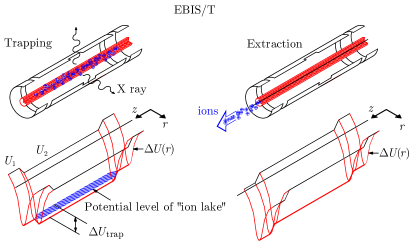
A trap formed by the axially symmetric smooth electron beam, which propagates through the cylindrical drift tube consisting of a few (at least three) sections with positive potentials applied to the edge sections, was suggested by E.D. Donets in 1967 1 . The method was realized in a device, which was named the Electron Beam Ion Source (EBIS). The ions are confined by volume charge of the electron beam and by external potentials at both ends of the drift tube. The depth of ion trap is given by difference of the maximum and minimum potentials: (see Fig. 2). The axially symmetric magnetic field is also applied to compress the electron beam and hinder the radial escape of ions from the potential well.

The original ion sources were developed for injection complexes of accelerators 2 . The devices were intended to provide the high-intensity ion beams. This required creation of the electron-optical systems with electron beam of about 1 m in length and characterized by current of a few Ampers 3 . For the ion sources employed in real accelerators, the electron current density falls in the range of 100–500 A/cm2 4 . Such values of are not sufficient for the production of highly charged ions of heavy elements of the periodic table. In 1986, the Electron Beam Ion Trap (EBIT) was constructed at the Lawrence Livermore National Laboratory (LLNL) for the purposes of X-ray spectroscopy 5 . Physically, the EBIT is similar to the EBIS operating in the trapping regime. However, the distinguishing feature of such device is the small length of ion trap of about 2 cm, what allowed one to increase significantly the current density up to 5 kA/cm2 and to ionize heavy elements up to uranium 6 . The classical Livermore EBIT with the electron beam energy of up to 30 keV is now widely replicated around the globe. The devices similar to the high-energy SuperEBIT aiming at the production of highly charged heavy ions were also constructed in Germany, Japan and China 7 ; 8 ; 9 . All the devices mentioned above employ the cryogenic engineering and superconducting magnetic focusing systems. These apparatuses remain to be very complicated and expensive to use and, accordingly, are available to large laboratories and national reseach centers only.
In 1999, a warm EBIT with electron beam focused by the radially magnetized permanent magnets was successfully tested in Dresden. A whole family of ion sources and traps named the Dresden EBIS/Ts was developed on the basis of this technology together with standard methods of obtaining the ultra-high vacuum 10 . At present, the devices operate at different universities and research centers. The important feature of the Dresden EBIS/Ts is a room working temperature, which significantly decreases the exploitation costs. However, although the electron beam energy achieved the values of about 10 keV, the current density of these devices does not exceed 0.3 kA/cm2.

II Main magnetic focus ion source
The electron current density is the key for the production of highly charged ions. In EBIS/Ts, the magnitude of for given values of the focusing magnetic field at cathode and the energy of electron beam is limited by requirements of the Brillouin focusing. In reality, the true density is even lower because of the influence of thermal velocities 11 . A substantial increase in current density can be achieved in the local ion trap formed by a rippled electron beam in a cylindrical drift tube 12 ; 13 ; 14 . In this case, the electron beam is focused by a thick magnetic lens in a sharp crossover, where can reach values of up to 100 kA/cm2. This principle is realized in the Main Magnetic Focus Ion Source (MaMFIS) (see Fig. 2). The device operates at room temperature due to the use of permanent magnets and standard vacuum techniques.
The depth of local ion trap is estimated as
| (1) |
Here and are the maximum and minimum values of radius of the electron beam, is the permittivity of free space, is the electron charge-to-mass ratio, is the accelerating voltage, is the perveance of the electron beam and is the electron current. The extraction of ions from the source is realized by changing the shape of electron beam. The rippled electron beam is transformed into a smooth flow with constant radius, when changing potential of the focusing electrode. Although the ion trap is just about 1 mm in length, it is compensated by extremely high values of and small sizes of the device.
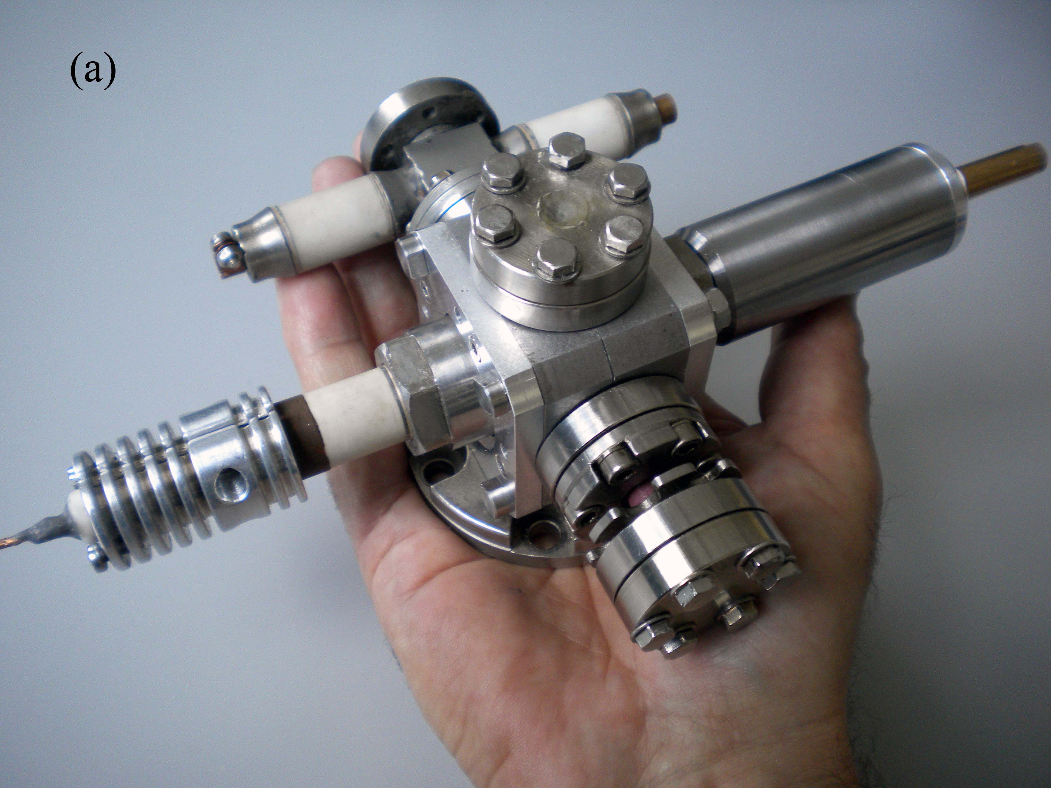
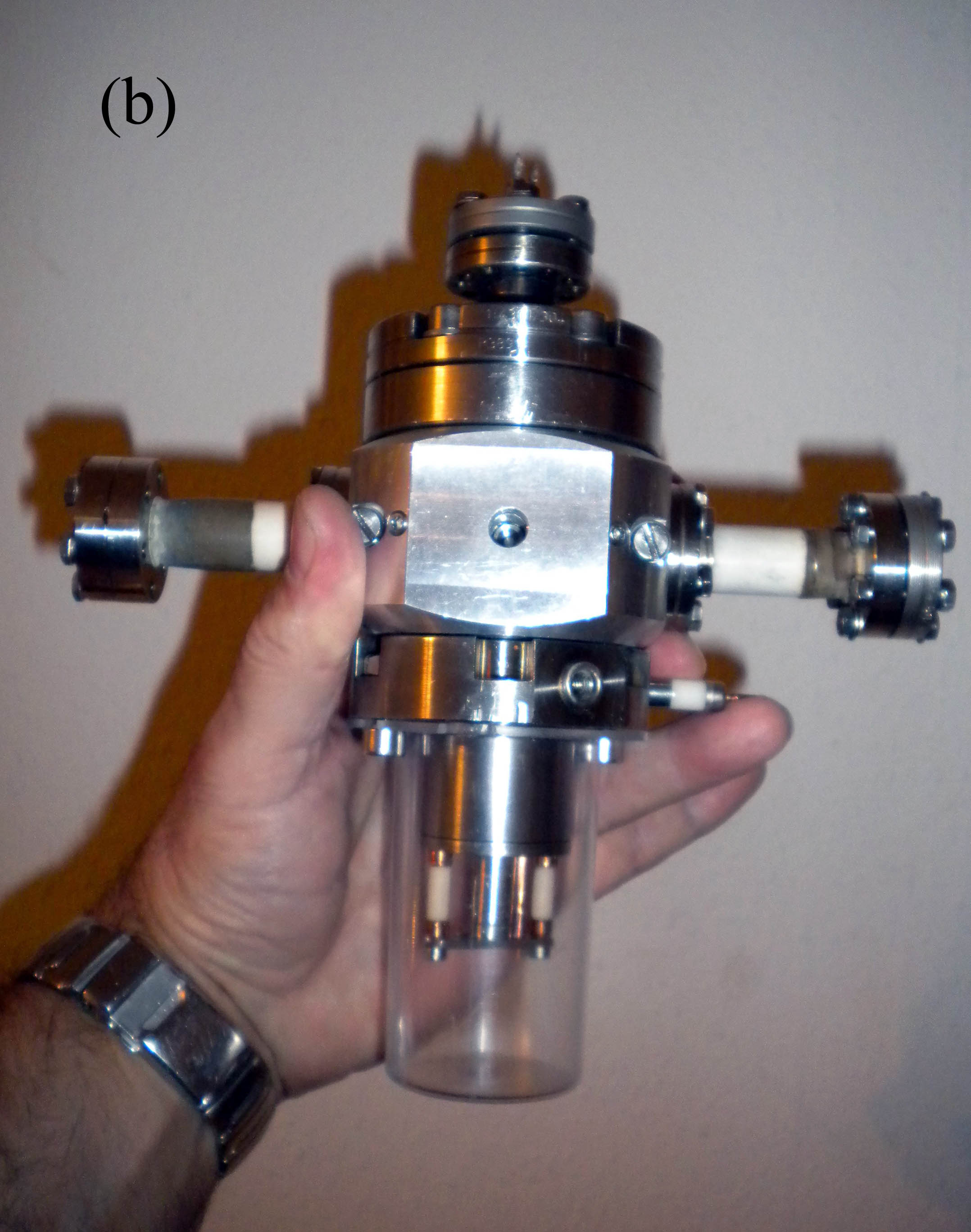
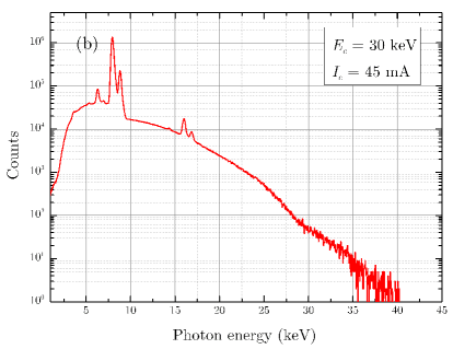
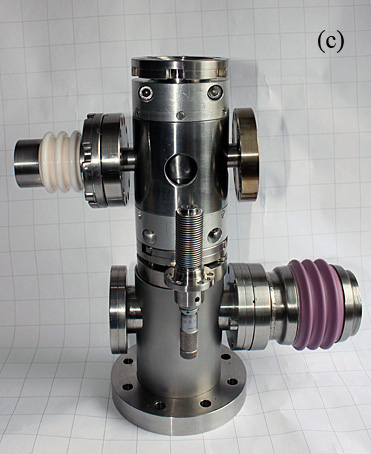
Presently, prototypes of the MaMFIS with of up to 4, 10 and 30 keV are constructed (see Fig. 3). The experimental measurements were performed at the Justus-Liebig University of Giessen. In Fig. 4, the X-ray spectra emitted by highly charged ions of the cathode material are presented for different electron beam energies. The radiation of iridium ions in charge states up to was identified. Analysis of the high-energy part of spectra due to radiative recombination with incident electrons allows one to estimate the current density at the level of about 10-20 kA/cm2 14 . A comparison of X-ray spectra from highly charged ions of cathode material in the classical Livermore EBIT (see Fig. 5 of work 5 ) and those obtained with the use of the MaMFIS-10 shows that these devices have comparable ionization efficiency. The first measurements of X-ray emission spectra from the MaMFIS-30 were performed for two discrete values of the magnetic field at cathode and different geometry of electrodes of the electron gun. Obviously, it is possible to implement a smooth movement of cathode in the focusing magnetic field and the fine tuning for the distance between cathode and anode in order to provide with sufficiently wide ranges for energy and current density of the electron beam.

III Classification of ion sources with respect to electron beam energy
The field of applications of EBITs is rather extensive. However, one can distinguish two areas of research, which require complementary energy ranges of the electron beam and, accordingly, different designs. The first area of research covers the low-charge ions produced in low-energy electron beams. In particular, one can mention here the spectroscopic data relevant to the sources of the extreme ultraviolet radiation (ions of Sn and Xe with the charge ) and diagnostics of high-temperature plasmas related to the solar corona (ions of Fe with ) and to fusion plasmas in the ITER reactor (ions of tungsten with ). In 2012, a compact EBIT with the energy of electron beam from 100 eV up to 2.5 keV was developed for these purposes at the University of Electro-Communications in Tokyo 8 . Similar devices were also built at the Fudan University and the National Institute of Standards and Technology 15 ; 16 .
From the other side, there is still a long-standing problem of complete ionization of heavy elements. In literature, it is known only one work, where about ten fully stripped U92+ ions were produced and trapped 6 . Despite long-term research on the SuperEBITs in Tokyo, Heidelberg and Shanghai, no one could reproduce the results obtained at LLNL. Since the binding energy of the -shell electrons in uranium is about 130 keV, the electron beam for such experiments should have very high energy not less than 200–250 keV. For ionization of all electron shells except for the shell of any heavy element up to uranium, the energy of electron beam should be at least 60 keV.
It is natural to separate a problem of ionization of the -shell electrons in heavy elements into a particular challenge. The energy regimes of electron beam within the range from 100 eV up to 60 keV can be realized in a single universal device, which combines technologies of the EBIS/T and MaMFIS. Therefore, it is enough to design just two ion sources for complete ionization of any element of the periodic table.

IV Universal main magnetic focus ion source
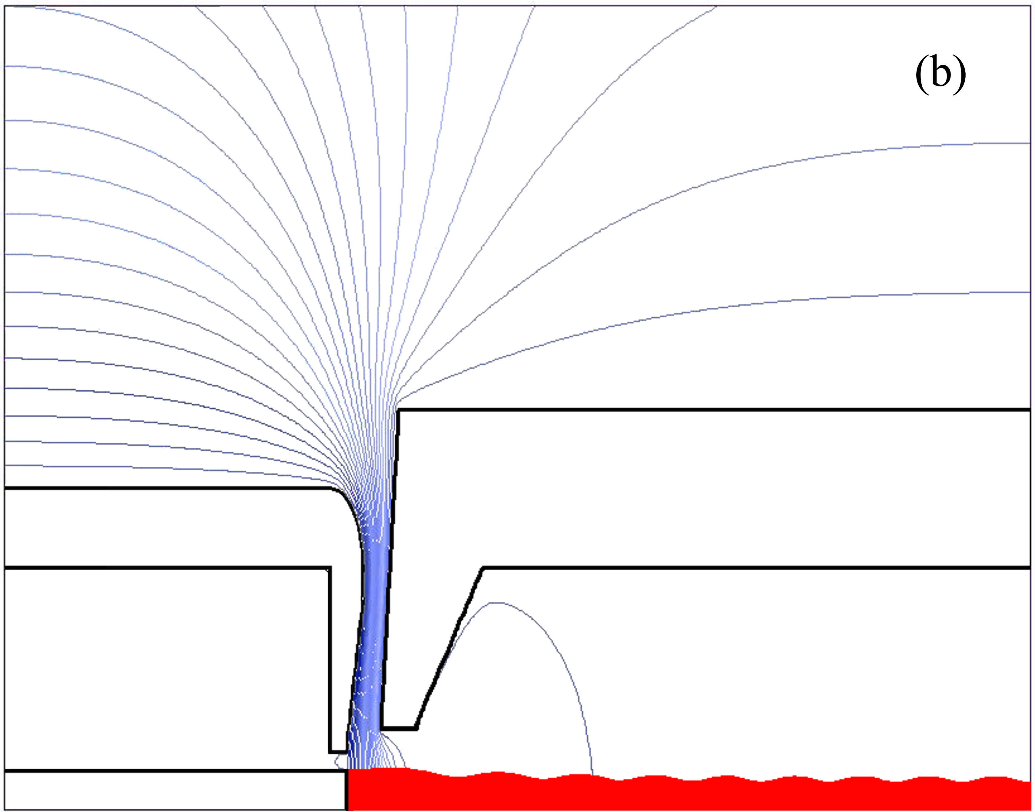
The ionization of both light and heavy elements in a single device is achieved by combination of two methods of focusing the electron beam, namely, by mix of the immersed () and fully immersed gun () techniques. In the first case, a rippled electron beam with high energy is formed for operation in the MaMFIS regime. In the second case, a low ripple electron beam with low energy is formed for operation in the EBIS/T regime. The movement of cathode in the electron gun is implemented by using the -manipulator 17 . The ion source becomes hybrid and is named the universal MaMFIS (UniMaMFIS). In Fig. 5, the electron trajectories are simulated for the MaMFIS-30. The UniMaMFIS upgraded up to keV is also presented. In Table 1, the project parameters of the device are given. The expected yield of Xe52+ is estimated at the level of about 300 ions per second.
| Operational regime | (keV) | (mA) | (A/cm2) | (cm) |
|---|---|---|---|---|
| EBIS/T | 0.1-20 | 10-200 | 10-500 | 2 |
| MaMFIS | 20-60 | 200 | 20000 | 0.1 |
| (keV) | 150 | 200 | 250 | 300 | 350 | 400 | 450 | 500 | 900 |
|---|---|---|---|---|---|---|---|---|---|
| (b) | 0.64 | 1.2 | 1.6 | 1.9 | 2.1 | 2.3 | 2.4 | 2.5 | 3.1 |
| (b) | 67 | 43 | 30 | 22 | 17 | 13 | 11 | 9.0 | 2.9 |

V Complete ionization of heavy and superheavy elements
The extremely high electron current density achieved in the ion trap together with relatively small size of the device and possibility to use the permanent magnets for focusing the electron beam allow one to apply the MaMFIS technology for efficient ionization of uranium and transuranium elements up to bare nuclei. The modern vacuum systems can provide ultra-low pressure (lower than mbar) of working gas in the MaMFIS chamber at a room temperature.
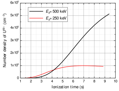
A steady charge-state distribution of ions is characterized by equality of the rates of ionization and competing processes. The latter involves mainly charge exchange and radiative recombination. Since the rate of charge exchange depends on number density of the working gas, the corresponding contribution can be suppressed at the expense of ultra-high vacuum in the ion trap. The radiative recombination occurs predominantly into the innermost electron shells, but its cross section decreases with increasing the electron energy (see Table 2). The K-shell ionization cross section is calculated for U91+ ions, taking into account the relativistic corrections 18 . As can be seen, the cross sections and become comparable at keV, that is, at about 7 threshold units. The production of bare uranium at keV is not very efficient, since is about 40 times larger than . In Figs. 7 and 7, the number densities of Uq+ ions are given as functions of charge states and ionization time , respectively. The computer simulations were performed according to work 19 for two energies of the electron beam. The corresponding estimates for yield of bare uranium give 1300 and 5000 nuclei per hour at keV and 500 keV, respectively.
Acknowledgements
The authors are indebted to A. Müller for giving opportunity to test MaMFIS at the Justus-Liebig University of Giessen, to A. Borovik Jr. for his support in X-ray measurements and to O.K. Kultashev and V. Kogan for their contribution to simulations of the electronic optics.
References
- (1) E.D. Donets, USSR Inventor’s Certificate № 248860 from 1967.03.16, Bull. OIPOTZ 23 (1969) 65.
- (2) E.D. Donets, Phys. Scr. T 71 (1997) 5.
- (3) A. Pikin, J.G. Alessi, E.N. Beebe, A. Kponou, R. Lambiase, R. Lockey, D. Raparia, J. Ritter, L. Snydstrup and Y. Tan, J. Inst. 5 (2010) C09003.
- (4) R. Becker and O. Kester, Rev. Sci. Inst. 81 (2010) 02A513.
- (5) M.A. Levine, R.E. Marrs, J.R. Henderson, D.A. Knapp and M.B. Schneider, Phys. Scr. T 22 (1988) 157.
- (6) R.E. Marrs, S.R. Elliott and D.A. Knapp, Phys. Rev. Lett. 72 (1994) 4082.
- (7) J.R. Crespo López-Urrutia, A. Dorn, R. Moshammer and J. Ullrich, Phys. Scr. T 80 (1999) 502.
- (8) N. Nakamura, Plasma and Fusion Res.: Rev. Articles 8 (2013) 1101152.
- (9) D. Lu, Y. Yang, J. Xiao, Y. Shen, Y. Fu, B. Wei, K. Yao, R. Hutton and Y. Zou, Rev. Sci. Inst. 85 (2014) 093301.
- (10) V.P. Ovsyannikov and G. Zschornack, J. Inst. 5 (2010) C11002.
- (11) G. Herrmann, J. Appl. Phys. 29 (1958) 127.
- (12) V.P. Ovsyannikov, Main Magnetic Focus Ion Trap, new tool for trapping of highly charged ions arXiv: 1403.2168 [physics.plasm-ph] (2014).
- (13) V.P. Ovsyannikov and A.V. Nefiodov, Nucl. Inst. Meth. B 367 (2016) 1.
- (14) V.P. Ovsyannikov and A.V. Nefiodov, Nucl. Inst. Meth. B 370 (2016) 32.
- (15) J. Xiao, Z. Fei, Y. Yang, X. Jin, D. Lu, Y. Shen, L. Liljeby, R. Hutton and Y. Zou, Rev. Sci. Inst. 83 (2012) 013303.
- (16) S.F. Hoogerheide and J.N. Tan, J. Phys.: Conf. Series 583 (2015) 012044.
- (17) V.P. Ovsyannikov, A.V. Nefiodov and O.K. Kultashev, Method and device for the production of highly charged ions Int. Patent Appl. № PCT/EP2016/055168, Pub. № WO 2016/142481 A1.
- (18) A.I. Mikhailov, A.V. Nefiodov and G. Plunien, J. Exp. Theor. Phys. 109 (2009) 762.
- (19) I.V. Kalagin, D. Küchler, V.P. Ovsyannikov and G. Zschornack, Plasma Sour. Sci. Technol. 7 (1998) 441.